Category Archives: Assignments

Week 7 Midterm – Lisa Ho


My midterm was a star constellation embroidery that lights up when you touch it and connect the thread together. I’ve always loved constellations and stars at night because I love how it lights up the dark. For this project, I used thread, conductive thread, water paint to paint the white fabric, LEDs, Attiny to make the LED light up, solder and hot glue to make my circuit connection stronger.

I sew my circuit of the light with conductive thread on another fabric and then embroidered the star embroidery to make sure that the two LEDs I’m lighting up are in the right places. Then I sewed it all together. And the end product is when you touch the two threads at the bottom, one LED will light up and when you connect the thread on top, the top LED will light up.

You can find the instructable here 

This is the Attiny circuit I made which is the basis of the code and circuit I used in my midterm.

Continue reading

Week 6 – Lisa Ho

I connected one of the soft switches I made to your Arduino. I used it to light up an LED. So when I pressed on the switch, the LED will LED up.

Then, I built a circuit with the switch and 3 LEDs. I light up the LED by using different pressure. When the sensor goes greater and equal than 100 but less than 200, the red LED will turn on. When the sensor goes greater or equal to 200, the blue LED will turn on and else the green LED will turn on.

Sadly, I lost the video I filmed. But I have the code which I will post below.

The materials used include Arduino, LEDs, soft switch I made out of felt and sponge, jumper wires, breadboard.

For Midterm

I love constellations. I am thinking of doing an embroidery and incorporating light into the embroidery so it lights up whenever I touch it. I’m thinking this could be an art that hangs up by my wall.


Continue reading

Week 7 – Dario Narvaez

For this week I followed the instructions proposed by Liza to create a circuit composed of 2 LEDs, 1 switch and a sensor, controlled by an ATtiny. To make the circuit I used a painted canvas as the base, conductive thread and conductive yarn, LED sequins, a 3V battery holder and a resistance of 10k. Something interesting from using a painted canvas is that you can draw a scheme of the circuit, a very nice practice to understand a bit more complex circuits before starting to sew.

As a precautionary measure, I used tape in some sectors of the circuit, to avoid any unintentional contact between the close thread lines.

Fluffy BMO & ATtiny Homework

ATtiny Circuit

Videos

Button

Switch

Fluffy BMO

FOR THE INSTRUCTABLE LINK:

https://www.instructables.com/id/Felted-BMO/


How I made it?

I start to use a foam as a base for the body. Then, embed the Matrix 8 by 8 in the front of it.

I work on a soft button which hides beside the body of the Robot


Week 6 – Youchun Zhang

Connect a soft switch to Arduino

Demo video IMG_0783

I used a switch from the swatch exchange and uploaded the “Blink” example to control the LED.

Connect a sensor to Arduino

Demo video IMG_0777

Step 1: Set up the LED

Step 2: Build the pressure sensor

Step 3:  Connect to Arduino

I added one if/else and set two thresholds – 450 and 900. When the sensor value is between 450 and 900, the LED will blink slowly. When the sensor value is larger than 900, the blinking will be much faster.

Midterm

For my midterm project, I would like to combine the open-weave pendant style with LED and create a lamp.

Week 6 – Dario Narvaez

To control the LED with the soft button, I used the switch I built in week 3 made out of folded paper, which adds elastic properties to the material. This pushbutton explores a fun way to activate and control a circuit. In this case, I’m connecting the button and the LED through Arduino using a basic digital read function from the inputs and a digital write for the output.

Materials

  • Arduino
  • x3 LEDs
  • Soft Button (Pushbutton)
  • Sensor made with Velostat and fabric
  • Jumper Wires
  • x3 220 k Resistor
  • x1 10k resistor

To control one or more LEDs with a sensor. First, I built a sensor using Velostat. Velostat is a material that must be calibrated very well, since the values can be very variable and instable. To turn the LED off and on using Velostat I used map function where I compared the minimum and maximum number displayed by the sensor (in this case 940 and 1023), with the minimum and maximum intensity of the led (0-255).

To control multiple LEDs with the sensor I created three conditions. When the sensor is pressed and the sensor value is less than 940, the LED 1 (white) illuminates, when the value is greater than 940 and less than 1023, the red LED will light up, and if it is 1023 or maximum pressure, the yellow LED will turn on.


Midterm Lamp

For the lamp I found inspiration by the drawings made by connecting dots as a playful way to interact with paper. The idea is grounded under this premise: Can you draw your own lamp? Can you activate the lamp by drawing it? Can you control the light by doodles? As you draw the icons, the circuit closes, and therefore turns on. If the drawing is erased, the circuit opens, and the lamp turns off.

This idea can be scaled to other icons and images such as candlesticks, light bulbs, lamps, etc…

The idea was born when I saw the technology with erasable conductive markers. Although this technology can’t be used in this case due to the limitations in terms of material and the fact that the object will be linked to a specific marker, I believe that I can achieve the same effect with magnets.

Week 6 – Anna Garbier

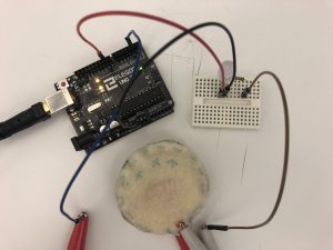
Part 1: Control an LED using a soft sensor and Arduino.


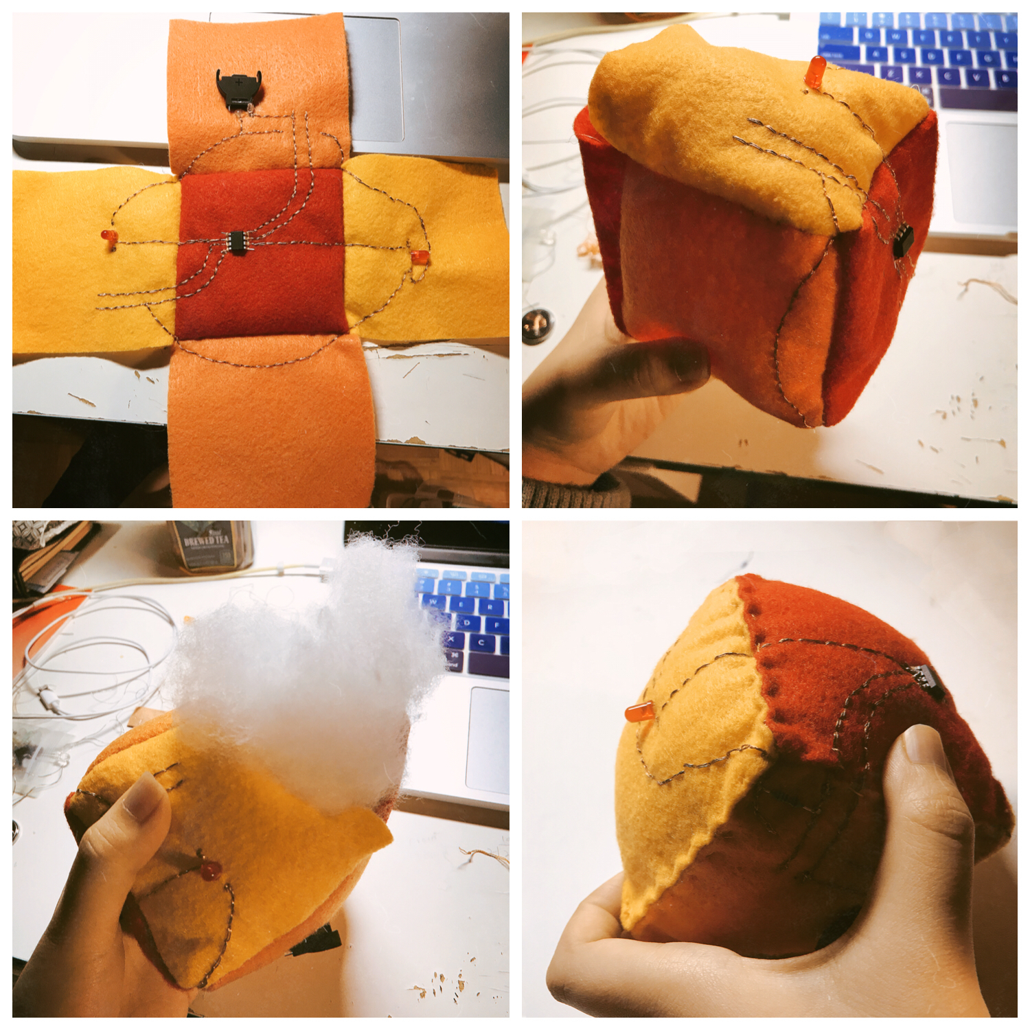
Part 2: Build a circuit with one constructed sensor (variable resistor), your Arduino, and 3 (or more) LEDs or an RGB LED.

Watch in action here; still images below.
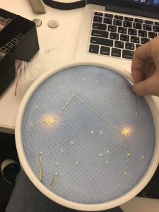
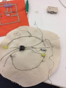
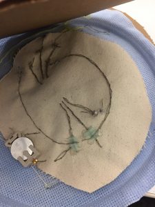
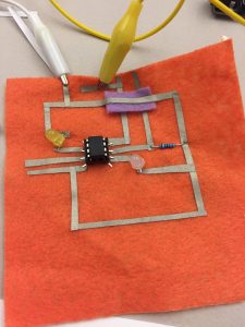
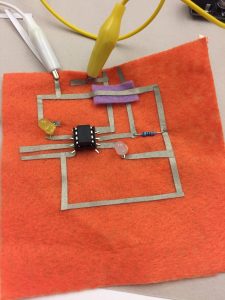
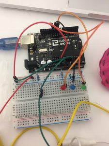
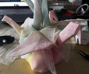
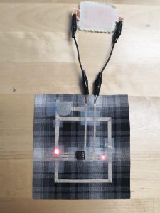
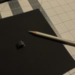
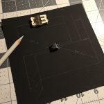
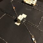
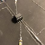
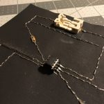
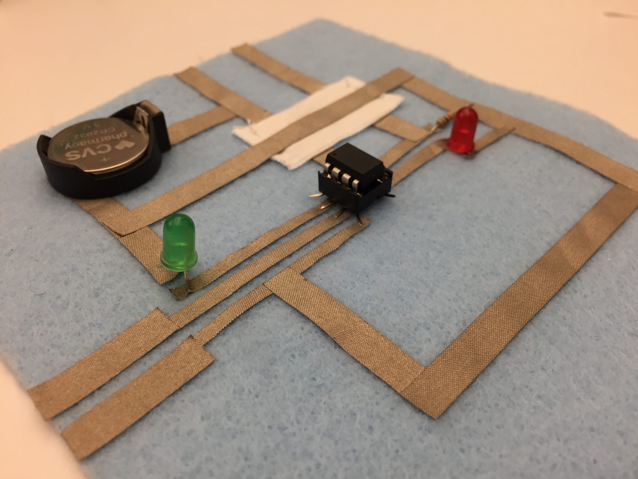
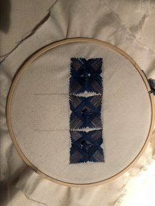
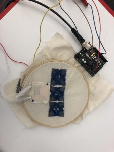
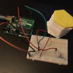
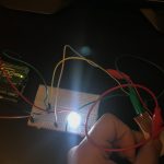
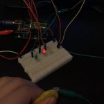
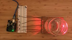
 (the setup)

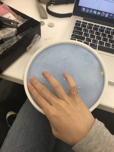
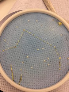
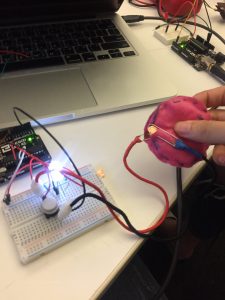
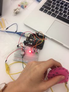
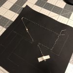
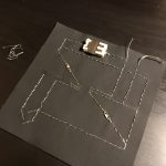
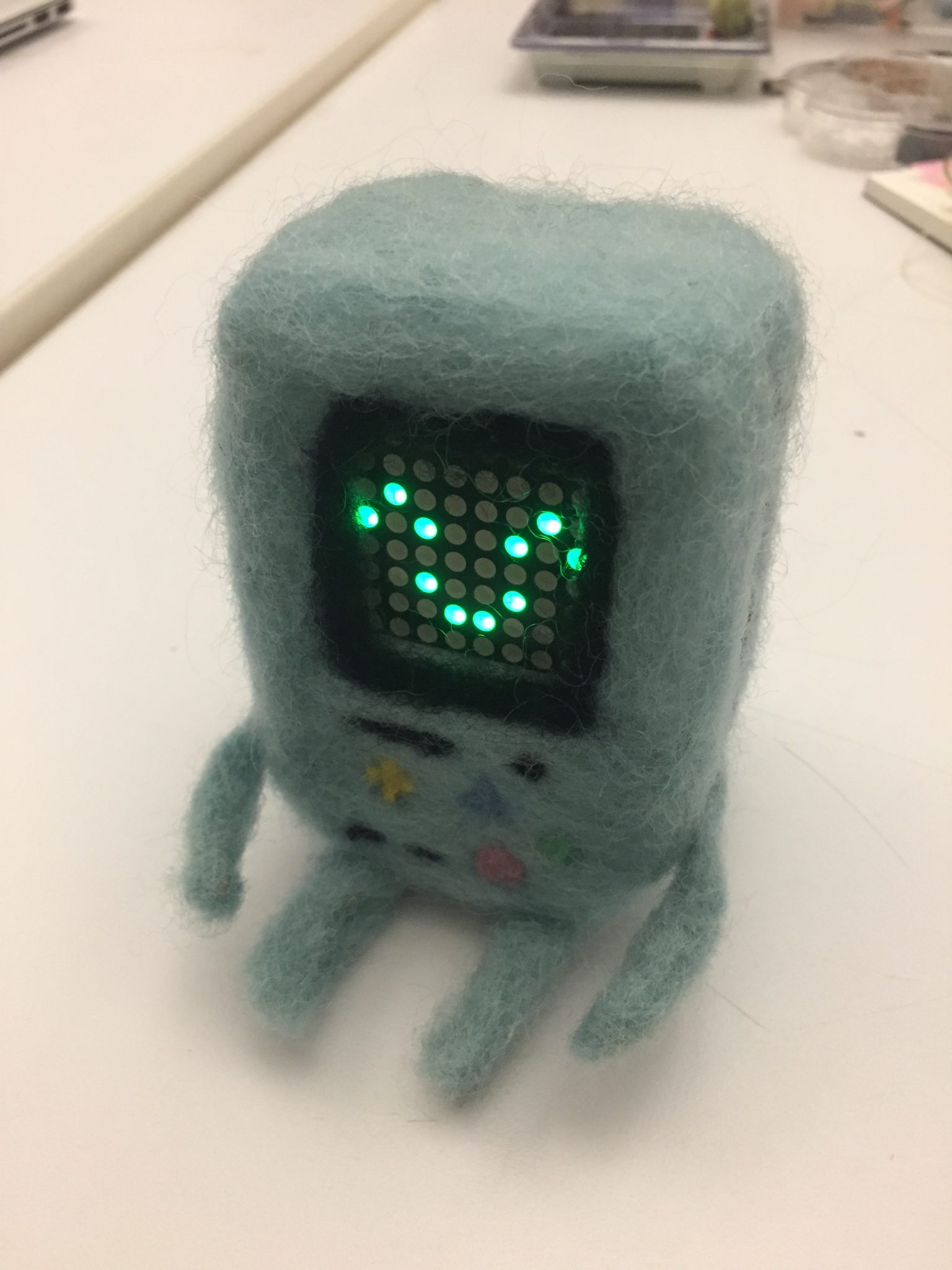
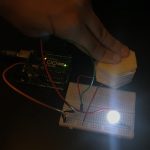
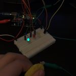
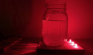
 (full glass on sensor triggers all three LEDs)

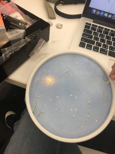
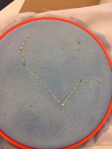
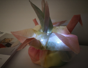
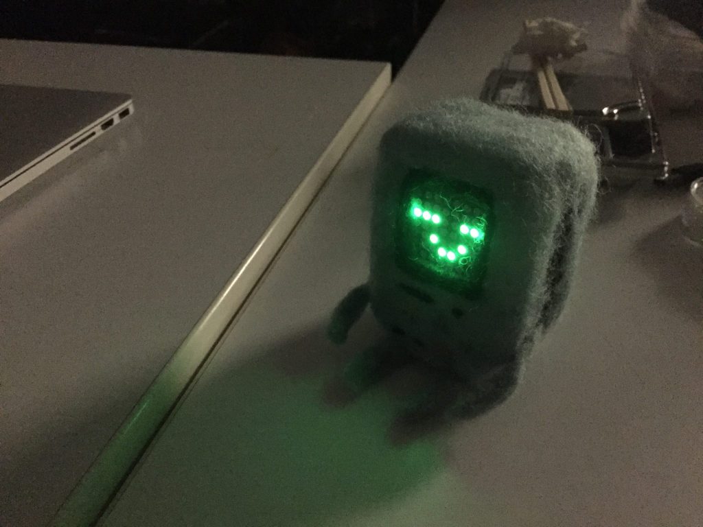
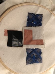
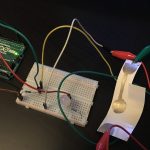
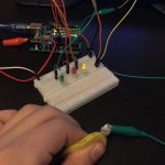
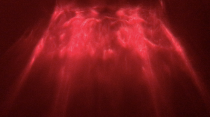
 (playing with light, water, and glass)

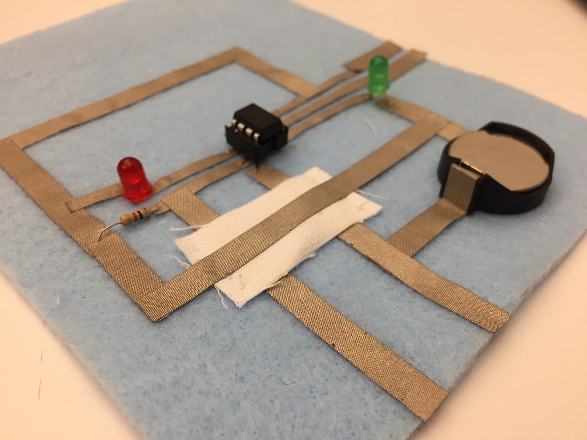
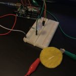
Summary: Arduino reads the analog input from a constructed pressure sensor, controlled for example by pouring water into a jar over the sensor pad. Based on the input, the Arduino controls three LEDs: the more pressure, the more lights turn on.

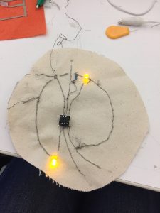
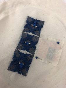
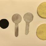
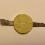
Pressure sensor materials: Velostat, conductive tape, cork, LEDs.

Code: https://github.com/annagarbier/annagarbier.github.io/blob/master/work/courses/2018/fall/computational_craft/resources/code/assignment_6.ino
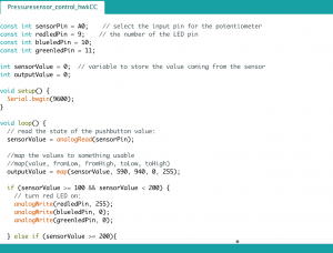
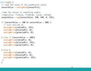
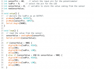
Code snippet:

```
// This function determines the LED pins' output (HIGH or LOW)
// based on the sensor pin's input (held in the variable "average").
void displayLights() {
if (average > 200) {
digitalWrite(ledA, HIGH);
digitalWrite(ledB, HIGH);
digitalWrite(ledC, HIGH);
} else if (average > 150) {
digitalWrite(ledA, HIGH);
digitalWrite(ledB, HIGH);
digitalWrite(ledC, LOW);
} else if (average > 100) {
digitalWrite(ledA, HIGH);
digitalWrite(ledB, LOW);
digitalWrite(ledC, LOW);
} else {
digitalWrite(ledA, LOW);
digitalWrite(ledB, LOW);
digitalWrite(ledC, LOW);
}
}
```

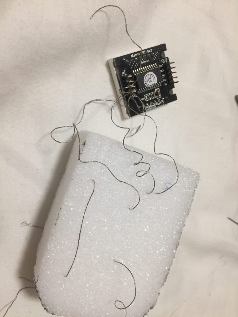
Part 3: Document midterm ideas.

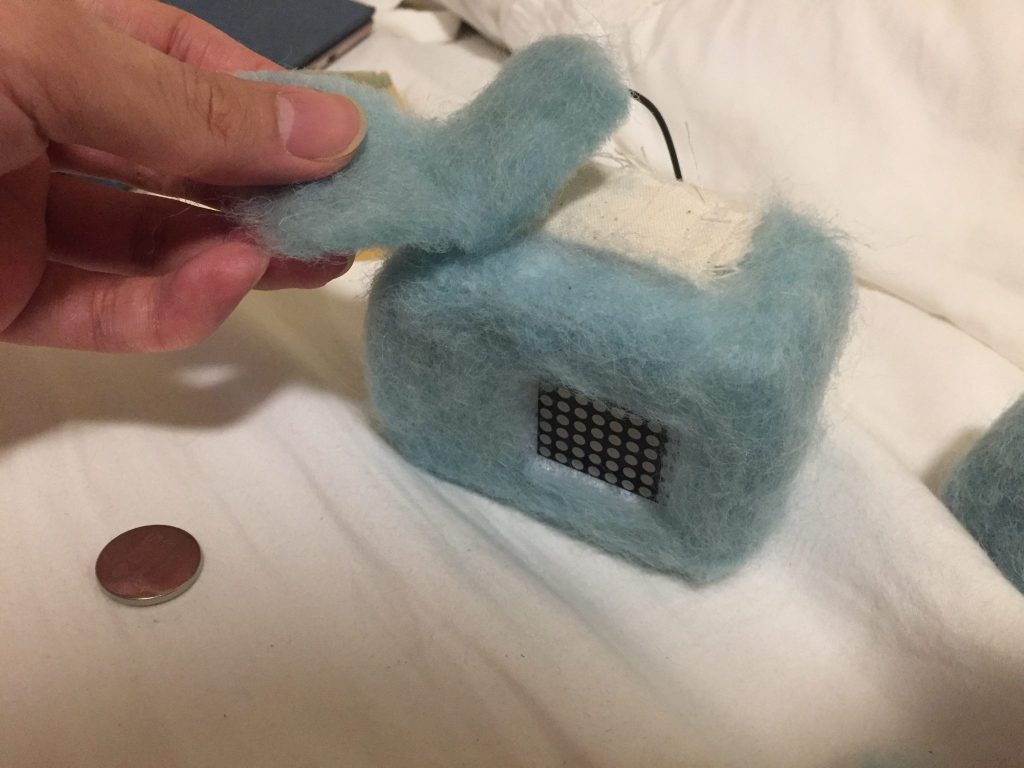
I’d like to create transparent modular blocks, each containing a piece of a circuit: e.g. one might contain a 3v battery, another a resistor, another an LED, and others just connecting components. A user would be able to play with the blocks by connecting them in 3d space; complete a circuit with the blocks, and the blocks with the LED shines.

The intention is to build something simple, playful, and educational.

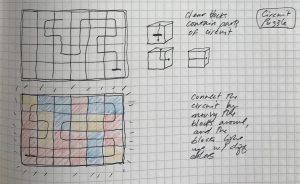
 (early ideation on paper)
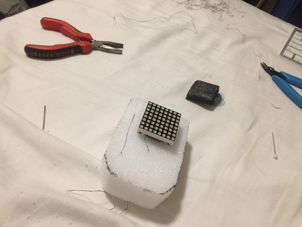
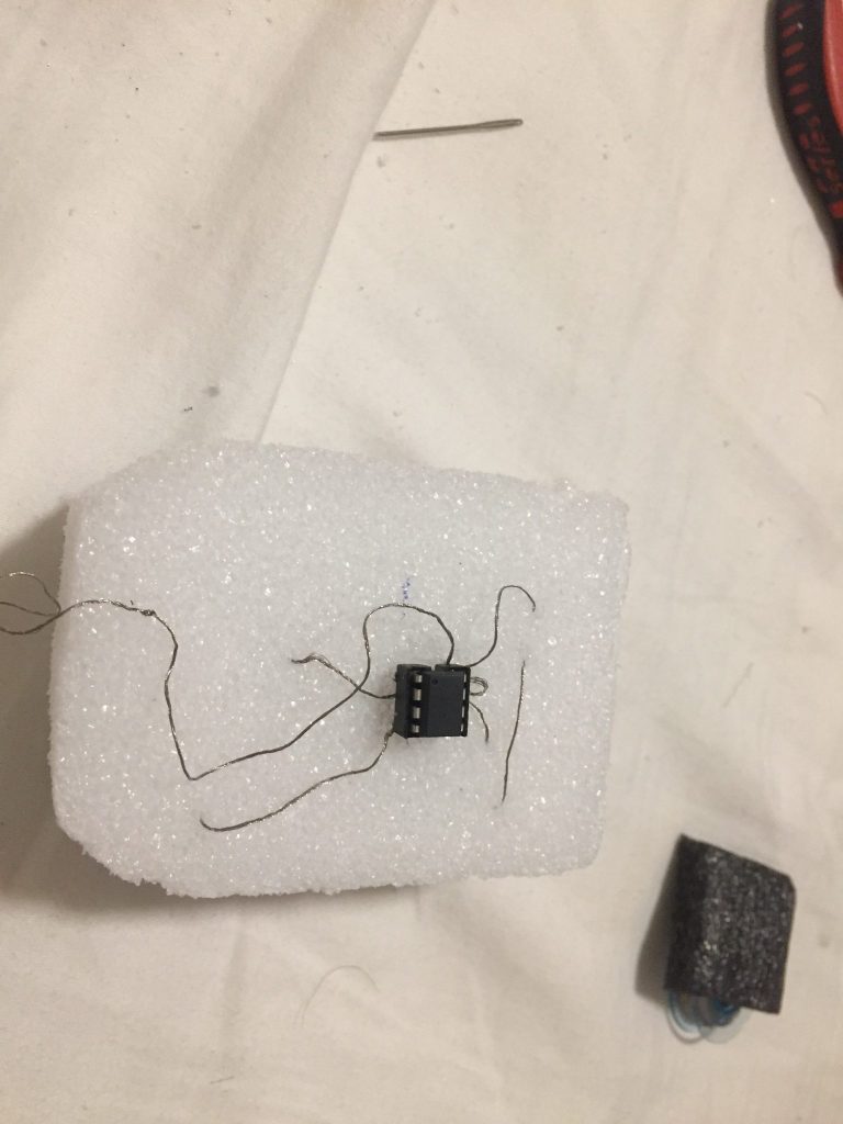
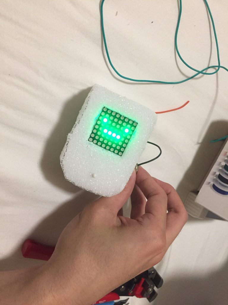
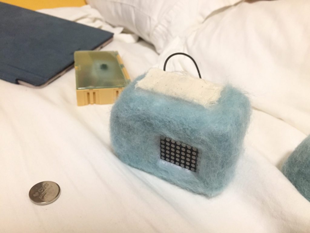
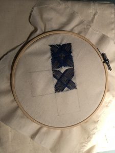
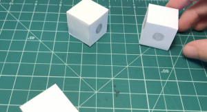
 (prototyping)