
Presentation: https://docs.google.com/presentation/d/1sUYrrKJgouIBgrMRpbiFp6CLde5otBWy1A05Q2PdyU4/edit?usp=sharing
Concept + Goals. What is your concept? What were your goals? Why did you decide on this project form for your concept and goal?
The Fortune Teller: Using an arduino, arduino printer, and a copper capacitive sensor I want to be able to give people a fortune based on the “random” amount of particles the sensor reads. Inspired by Mary Poppins measurement tape that collects the input of height and gives a corresponding description, “Perfect in everyway” and Zoltar, I want to design a fortune teller that reads its participants touch and subsequently gives them a corresponding fortune.
Intended audience. Who is this for? Why did you choose this audience?
Given that my idea of a fortune teller utilizes a non-invasive sensor my intended audience is anyone who is conveniently available and interested in getting a fortune.
Precedents. Share any precedents that inspired you.
Since one of the main components, if not the, of my project is to be able “sense” some aspect of my participant(s) I needed a sensor that could do just that in a relatively quantifiable way. I considered using a TMP36 Temperature Sensor so when a participant would get near/ touch the fortune teller depending on the temperature the fortune would change. Upon further deliberation, I believe most people range within the same body temperature so I wanted to use a component that could sense something with more range. Tubah (a tutor) recommended a capacitive sensor.
- TMP36 Temperature Sensor: Based on the principle; as temperature increases, the voltage across a diode increases at a known rate. By amplifying the voltage change, a output proportional to temperature can be produced.
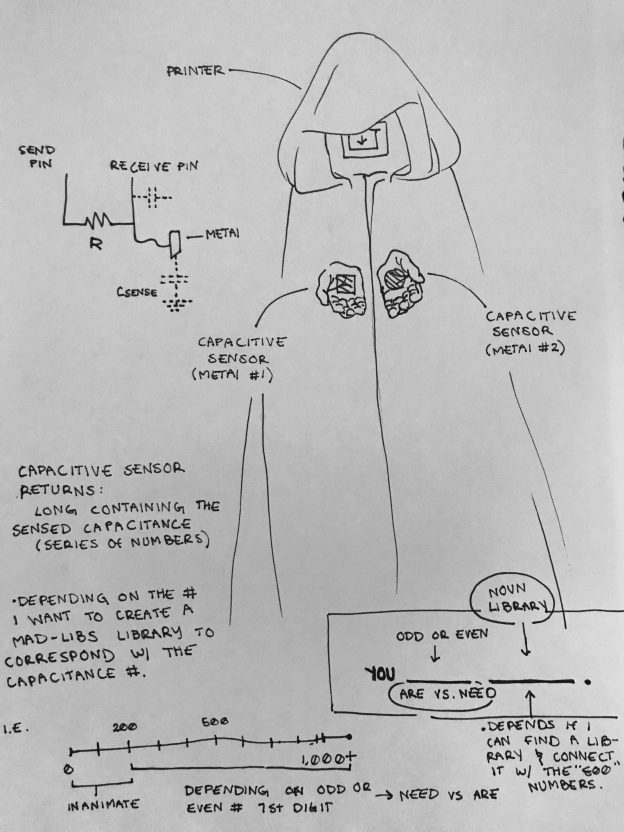
The capacitor is a component which has the ability or “capacity” to store energy in the form of an electrical charge producing a potential difference (Static Voltage) across its plates, much like a small rechargeable battery. Capacity is very sensitive and can be affected from a variety of environmental factors making it’s output very inconsistent. Accordingly, using this aspect to my advantage when touched all individuals can produce a unique capacitance… therefore fortune.
Description of the project. Discuss the process of creating this project. How does it work? What is the desired interaction?
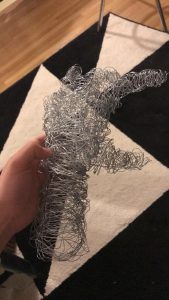
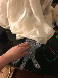
This project is simple in its composition. It utilizes a single sensor, capacitive, and a single mode of output, a printer. I started the project with the physical components; the capacitive sensor and then the thermal printer. I found different tutorials for physical component that related to the outcome I needed. For example the capacitive code I used had a pre-set threshold of a 1000 and utilized an LED to show that the capacity was being read correctly. These details came in handy when it was no longer plugged into a monitor that could read the resistance since the LED would alert me to if the capacity was being read correctly. My next step after the physical setting up that was connecting the two through the code; have the printer respond to a capacitance that passes a threshold and have ranges equal different “fortunes.” I originally wanted to design two plaster hands that had metal wire running through them thus becoming the capacitor. With this idea, the participant would put their hands in the fortune teller’s hand, mimicking the interaction of a stereotypical gypsy fortune reading, and get their fortune. Though after the Parsons 2 building accident, which affected the wet lab, I used garden wire wrapped together as the hand instead. Ultimately, the project was successful. I made a capacitive sensor that was able to read capacity through a metal-wire-hand and subsequently read that input and print the corresponding fortune through code in the Arduino.
- Materials list. List the materials you used and link to where people can purchase.
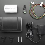
- .Thermal Printer — It comes with all these materials
- thermal receipt paper
- 5V 2A power supply
- 2.1mm DC jack adapter
- Power Cord supply to the printer
- Resistor (100k ohm)
- LED (Red)
- Breadboard
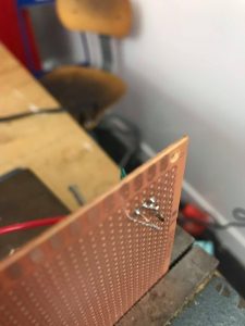
- Copper Solder Board
- Arduino + USB cord
- Solder
- 3 Jumper Wires
- Metal:
- Aluminum foil
- Wire Hand: Garden Wire
- Chipboard
- Clothe (for the robe)
- .Thermal Printer — It comes with all these materials
Process + Prototypes. Discuss the process of creating this project. Show your prototypes, playtests, sketches, interaction diagrams, and any other files that illustrate the tools you used. What challenges did you faced?

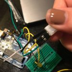
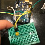
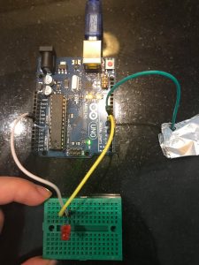
- Capacitor: I began assembling my project starting with the capacitor. While I waited for the thermal printer to arrive this component was pretty simple to construct. Using online sources for the code and the Arduino capacitive library, I successfully was able to read the capacity of myself using aluminum foil as the sensor.
- As seen through the video featuring the serial monitor, when the capacity passes a certain threshold (1000) the LED will turn on. Alone the capacity of the aluminum foil and the environment have stayed under the threshold, nevertheless the capacity has been changing frequently from 60s-90s to 250s-290s.
- Materials:
- Resistor (100k ohm)
- LED (Red)
- Breadboard
- Arduino + USB cord
- 3x Jumper Wires
- Metal: Aluminum foil
- Code:
- Code: Capacity Code
- Library: Capacity Library
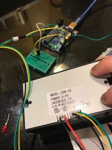
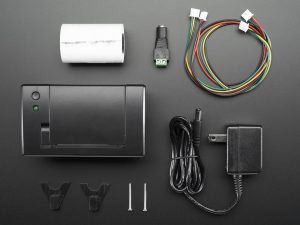
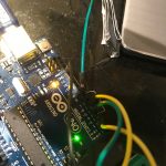
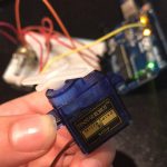
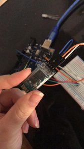
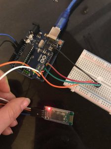
- Thermal Printer: Once the thermal printer arrived I was able to get started. Getting the thermal printer functioning using the example code and downloading the printer library was a success. Using the set-up tutorial Thermal Printer Setup went smoothly as well. As seen in the video I got the example receipt to print and the capacitor to work individually.
- As iterated in the video, the next step for me is to combine the two codes and get the arduino to read the capacitor’s input and in response print the output.
- Materials:
- A mini thermal receipt printer
- thermal receipt paper
- 5V 2A power supply
- 2.1mm DC jack adapter
- supply to the printer
- 3x MM jumper wires
- Code:
- Code: Example Code → Adafruit Barcode
- Library: Adafruit_Thermal.h

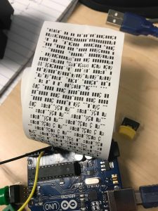
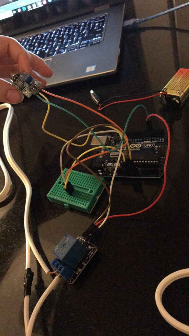
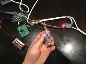
- Code: As someone who doesn’t know how to code I went to the LC for help getting started. Off the bat, I had 3 major goals; 1)Get the printer and the capacitor onto the same code 2) Get the printer to print when the threshold is met 3) Print a fortune based on the different ranges of capacitance. Starting with step 1, I met with Tubah and by the end of the session we got the capacitor, arduino, and printer connected. However, the printer was unable to print the correct symbols (we were testing with the arduino test barcode). Matter of fact it was printing an infinite series of illegible symbols. With this I added new goals to my list; figure out why the 4) illegible symbols was printing 5) why the printer is continuously printing.
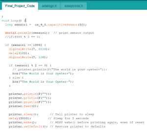
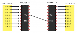
The following session I met with Aarati and we found that the illegible symbols was due to baud-rate and or Arduino syntax between softwareserial/ mySerial.begin and Serial.begin. This was also connected to why the serial monitor wasn’t responding. Once we got the printer to respond to the capacitor we found that the printer will continuously print because capacity is read in milliseconds when touched. A solution to this was to add a timer for when the capacitance passes the threshold. We did this and got the connecting code working perfectly. The next step was to make ranges of capacitance with corresponding fortunes and with the help of Aarati that was easy. We even included a component that changed the fortune depending on whether the capacitance number read was odd or even.


- Finishing Touches:
The soldering, wire hand, chipboard silhouette, and the robe were simple add-ons that made the final product look more polish. - What would you do in a future iteration?
Towards the end of my project my arduino code was nearing the maximum memory capacity ergo a future iteration might use a Raspberry Pi and may also have a cleaner and more artful design on the print. - Assembly:
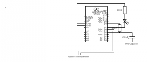
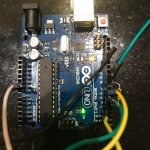
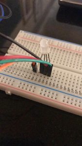
- Capacitor & LED:
- Starting with the capacitor and LED find the highest resistor you can grab, (I used 150.5K) and put it on the Arduino ~4pin and ~8pin
- Use the dedicated power cable and connect it positive side of the LED and plug the other into ~7pin
- Use the dedicated ground cable and connected it to the ground end of the LED and plug the other into GND on the Arduino.
- Place the LED in the breadboard connecting them with the GND and power wires.
- Optional; Include 220 ohm resistor in breadboard. I ended up using one when I soldered the board, but it’ll work without it.
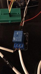
- Printer: Using the Arduino Thermal Printer Pack
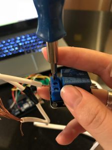
- Plug in the GND (black) and VH (red) F wires into the printer
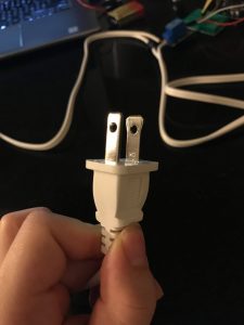
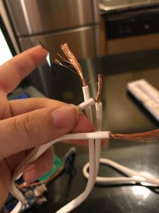
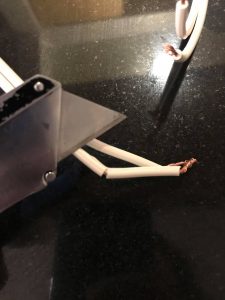
- Cut off the open end of the Red and black wires to expose the metal inside.
- Using the DC adaptor put in the exposed black and red end of the wires
- Make sure they are oriented correctly
- Plug in the GND (black), RX (yellow) and TX (Green) wires into the printer
- Using the 3 MM jumper wires attach them to the open end of the GND, RX and TX cord.
-

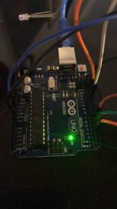
- Insert the TX (green) wire into the digital ~5 pin of the Arduino
- Insert the RX (yellow) wire into the digital ~6 pin of the Arduino
- Insert the GND (black) wire into the GND (any of them) of the Arduino

- Download the necessary Libraries:
- #include <CapacitySensor.h >
- #include ” Adafruit_Thermal.h “
- #include “adalogo.h” (found in Thermal.h)
- #include “adaqrcode.h” (found in Thermal.h)
- Code:
- Copy and Paste my Code: (Feel free to edit how you like)
- Thermal Printer and Capacity Code Final
- #include <CapacitiveSensor.h>
CapacitiveSensor cs_4_8 = CapacitiveSensor(4, 8); // 1M resistor between pins 4 & 8, pin 8 is sensor pin, add a wire and or foil
#include “Adafruit_Thermal.h”
#include “adalogo.h”
#include “adaqrcode.h”int LED = 8;
int buttonpin = 3;
//FIND A 10K resistor! Check if this is still relevant.#include “SoftwareSerial.h”
#define TX_PIN 6 // Arduino transmit YELLOW WIRE labeled RX on printer
#define RX_PIN 5 // Arduino receive GREEN WIRE labeled TX on printerSoftwareSerial mySerial(RX_PIN, TX_PIN); // Declare SoftwareSerial obj first
Adafruit_Thermal printer(&mySerial); // Pass addr to printer constructor
// Then see setup() function regarding serial & printer begin() calls.// Here’s the syntax for hardware serial (e.g. Arduino Due) ————–
// Un-comment the following line if using hardware serial://Adafruit_Thermal printer(&Serial1); // Or Serial2, Serial3, etc.
// ———————————————————————–
void setup() {
cs_4_8.set_CS_AutocaL_Millis(0xFFFFFFFF);// turn off autocalibrate on channel 1 – just as an example
pinMode(7, OUTPUT);
// pinMode(7, OUTPUT); digitalWrite(7, LOW);
// This line is for compatibility with the Adafruit IotP project pack,
// which uses pin 7 as a spare grounding point. You only need this if
// wired up the same way (w/3-pin header into pins 5/6/7):
pinMode(5, OUTPUT); digitalWrite(5, LOW);
pinMode (buttonpin, INPUT);
// cs_4_8.set_CS_AutocaL_Millis(0xFFFFFFFF);// turn off autocalibrate on channel 1 – just as an example
// Serial.begin(9600);
// pinMode(7, OUTPUT);
// NOTE: SOME PRINTERS NEED 9600 BAUD instead of 19200, check test page.
pinMode(LED, OUTPUT); digitalWrite(LED, LOW);
Serial.begin(9600);
mySerial.begin(19200); // Initialize SoftwareSerial
//Serial1.begin(9600); // Use this instead if using hardware serial
printer.begin(); // Init printer (same regardless of serial type)}
void box(char *string) {
uint8_t i, len = strlen(string);
//printer.write(0xDA);//upper-left corner
for (i = 0; i < len; i++)printer.write(0xC4);// Top Edge
// printer.write(0xBF);// Upper-right corner
printer.setSize(‘S’); //Size
//printer.println();//NewLine/Feed
//printer.write(0xB3); //left edge
printer.print(string);
//printer.println(sensor1); How to print the capacity ?
//printer.println(0xB3);
// printer.println(0xB3);
//printer.println();//Newline/Feed
// printer.write(0xC0); //Lower-Left corner
for (i = 0; i < len; i++) printer.write(0xC4);//Bottom Edge
//printer.write(0xD9); //Lower-right Corner
printer.println();//NewLine/Feed
}void loop() {
long sensor1 = cs_4_8.capacitiveSensor(50);Serial.println(sensor1); // print sensor output
//if(4999 % 3 == 0)if (sensor1 >= 4000) {
digitalWrite(7, HIGH);
delay(100);
digitalWrite(7, LOW);if (sensor1 % 2 == 0) {
// printer.println(F(“The world is your oyster+”));
box(“The World is Your Oyster+”);
} else {
box(“You Are Special-“);
}printer.println(F(“”));
printer.println(F(“”));
printer.println(F(“”));
printer.feed(2);printer.sleep(); // Tell printer to sleep
delay(3000); // Sleep for 3 seconds
printer.wake(); // MUST wake() before printing again, even if reset
printer.setDefault(); // Restore printer to defaults} else if (sensor1 >= 2950) {
digitalWrite(7, HIGH);
delay(100);
digitalWrite(7, LOW);if (sensor1 % 2 == 0) {
box(“Have Empathy+”);
} else {
box(“Don’t Be Too Manipulated By Emotions-“);
}printer.println(F(“”));
printer.println(F(“”));
printer.println(F(“”));
printer.feed(2);printer.sleep(); // Tell printer to sleep
delay(3000); // Sleep for 3 seconds
printer.wake(); // MUST wake() before printing again, even if reset
printer.setDefault(); // Restore printer to defaults
- #include <CapacitiveSensor.h>