Concept + Goals: With this project, I sought to create an interactive exhibit that complements the ‘Me Too’ and ‘Time’s Up’ movements. These were my guiding design questions:
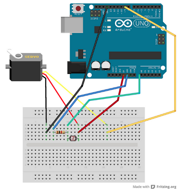
This week I prototyped the most basic functionality of my project:
when the photocell is covered, servo motor stops. When photocell is uncovered, servo motor sweeps 180º.
Over the next week I will iterate on this by both multiplying instances of the functionality and giving shape to the story (adding the hammer to the motor, embedding photocell in foam core poster).
I used a few web resources for this code, which are listed at the top of my .ino sketch for now.
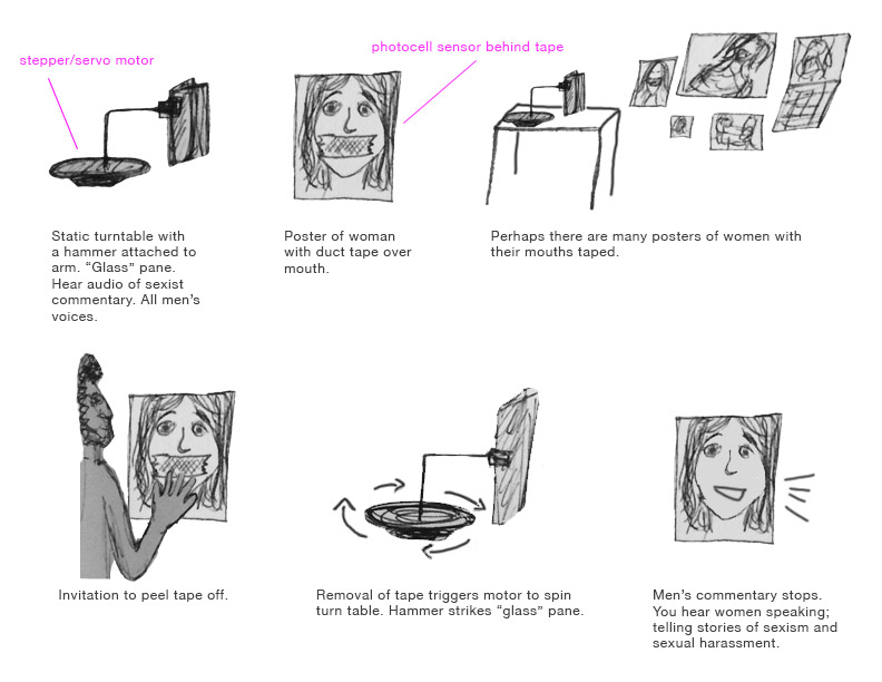
This will be a small installation that explores sexism, objectification, and empowerment through voice. There will be a motorized arm with hammer, aligned to strike a perpendicular ‘glass’ pane. Accompanying the hammer/glass structure will be a printed poster of a woman with tape over her mouth. Upon introduction to the installation, the motorized arm will be static and audio can be heard: sexist commentary from men. There will be some invitation to the audience to peel back the tape from the poster. The removal of the tape will trigger the motor to start spinning, and thus the hammer to start striking the ‘glass’ pane. The audio will be replaced by women’s voices, consecutively telling their stories of sexism and sexual harassment. The hammer will continue striking until the tape is placed back over the poster’s mouth, returning status quo…or until the ‘glass’ shatters.
DC motors rotate continuously. Their speed is controlled by PWM, which actually turns the motor on and off so rapidly it looks like a smooth movement. DC motors rotate until power is detached.
Servo motors are good for exact tasks because they can be more precisely controlled than standard DC motors. Power to the motor is constant but regulated by the servo control circuit. PWM “unlike DC motors it’s the duration of the positive pulse that determines the position, rather than speed, of the servo shaft.” (source: https://www.quora.com/What-is-the-difference-between-a-DC-motor-a-servomotor-and-a-stepper-motor)
Stepper motors use electromagnets around a central gear to determine the position. Each electromagnet must be individually powered to make the motor shaft turn.
Communication is asynchronous, meaning it does not depend on a synchronized clock signal between the two devices. You can set the data transfer speed and format as needed — you basically set an agreed-upon timing between the two devices.
Choose one of the wireless topics covered in class and put it to practice for use in everyday life. For example, use the IR sensor with a remote control to make a fan for a hot summer day.
Document your project in action and post to the class blog, including the list of materials used, a circuit schematic, and notes regarding wins and challenges.
Setup: 3 buttons and 2 LEDs with resistors wired to arduino. When the right combination of buttons is pressed, unlock and shine the green LED. Otherwise, lock and shine the red LED.
How it works:
Starts in a locked status, indicated by red LED.
Enter the following combination of buttons to unlock:
Button 1: 2 presses
Button 2: 1 press
Button 3: 2 presses
This combination unlocks, indicated by green LED.
To lock: press each button once. This triggers each button count to exceed the maximum limitation and thus reset to 0.
We chose to take a closer look at resistors because they’re essential to almost every circuit and involve a bit of calculation to understand and use properly. If we can succeed in fostering a better understanding of resistors, we can make circuit-friendly calculations and discernments quicker and better.
Challenges: We didn’t hit much resistance…sometimes it was tricky to balance the “right” amount of information to include.
Wins: This booklet seems pretty handy for a novice!