Poetry, polity and power is the culmination of two disparate ideas that I have been intrigued by this past semester. The first is about a new kind of interaction that is emerging between human beings and machines as technology gets integrated into everyday processes. The common perception of technology or computerized systems being objective is a myth- they embody the values and perspectives of the people who design them. The second is about the power of art and poetry- and how they can be used as dynamic tools for resistance.
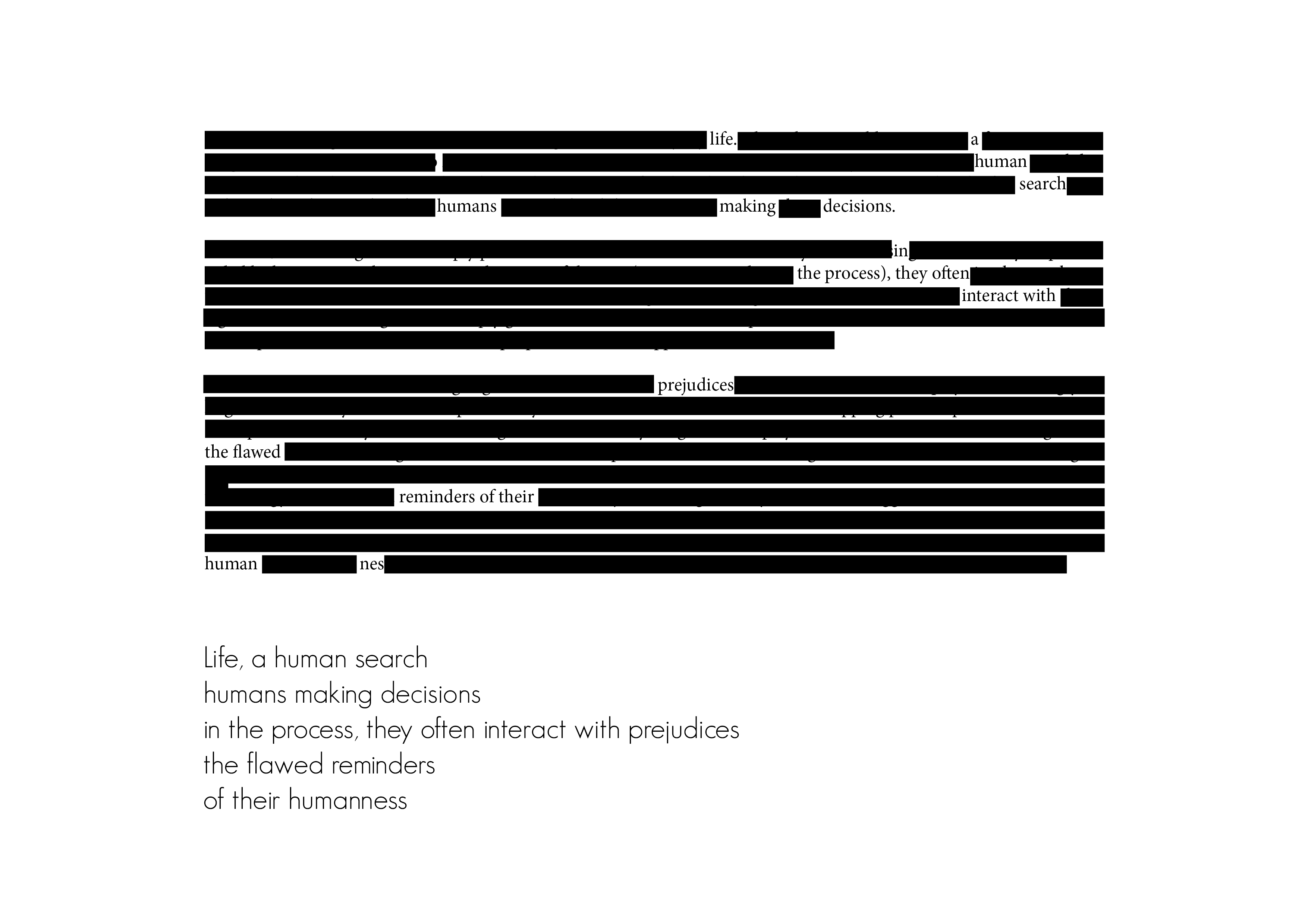
Poetry, power and polity is an optimistic poetry generator that can be fed biased text- hate speeches, discriminatory policies, misogynistic statements- and it removes words to create poetry that is hopeful and empowering. I wanted to create a computerized system that would automatically generate poetry from the source text- without human intervention. I see this project as a conceptual prototype that captures the essence, the value inherent in the idea- but needs further iterations to be fully realized.
In its current form, the generator would be more effective if it could respond to different source texts- by activating different heating pads depending on which text was fed in. Future iterations include programming a system that can operate on its own. Possible ways to do this would be to train Machine learning algorithms using many such blackout poetry examples.
The challenges for this project were mainly working with unfamiliar material, that was inconsistent and would react differently on different days. It taught me the importance of experimentation. Powering the circuit using the wall wart was challenging too- mainly because I found very limited documentation on it.
I loved working on this project though because I realized how simple, basic materials, mechanisms and methods can be used to convey ideas.
After brainstorming this past week, I decided to explore my second idea in greater detail. I am excited by the prospect of using art and poetry as dynamic tools of resistance to counter biases and protest against skewed power structures.
I want to create a blackout poetry generator- which on being “fed” text can create hopeful, optimistic poetry. Blackout poetry is a genre of poetry, where removing pieces of narrative helps craft a new story.
Using a tech crunch article about bias in algorithms
Using a 1973 advertisement by Donald Trump, advocating the death penalty
Systems flow
Ideally, I would like to create a program that could computationally generate meaningful poetry from the snippets of text it is provided. I was imagining a setup, where the input could be either analog (piece of paper) or digital(article), the text would be analyzed and blackout poetry generated. The challenge is then to make something that is not only grammatically but syntactically correct too.
Prototype
For this prototype, I decided to experiment with thermochromic pigment, which has heat sensitive compounds that change color upon reaching a certain temperature. I was working with black thermochromic pigment, which on being heated becomes clear. I tried using it with two types of glue and paint to see what would work the best. After applying the mixture to paper, I tried creating a circuit using Copper tape to heat certain portions of the text. I am unable to reach the appropriate temperature that would activate the color change.
Challenges and future iterations
Midway through the exercise, I realized that I want the color to change from clear to black and not the other way round. I wonder if a better alternative would be to use cooling pads instead?
Also, I wonder if there are alternatives to using thermochromic ink- could there be a motorized system instead- which on receiving the input (the hate speech, for example), dispenses/ outputs the blackout poetry?
At this time, there are mainly two ideas that I am thinking about. This past semester, I have been intrigued by the interaction between man and machine- the areas of overlap, the process of co-creation, almost-collaboration that has become commonplace as traditional processes become automated. This area of inquiry is very nuanced and layered- which makes it difficult to categorize it into the binaries of good/ bad or right/ wrong. I am imagining an exhibit, with two different sections- one about machines and humans creating generative art together. The second would be about machines re-inforcing human bias.
The second idea revolves around poetry and power. I want to infuse optimism in instances which show the very worst of human existence- by changing the context of the narrative. I envision a space, with a series of artifacts that explore this theme.
Timeline
Week 11: April 2nd – April 8th
Research, brainstorm, ideate and keep refining the concept statement. Define the audience and context of use. Look at relevant precedents and work that inspires me. Experiment with different ways of inputting information.
Week 12: April 9th – April 15th
Finalize project form. Prototype the technical build of the project and simultaneously start thinking about the look and feel.
Week 13: April 16th – April 22nd
Start assembling/ working on the smaller circuitry that will be a part of the larger project. At the same time, start building/ working on the final fabrication.
Week 14: April 23rd – April 29th
Keep working on the final project. Start preparing the presentation (research + precedents + concept + project documentation).
Week 15: April 30th – May 6
Work on the final presentation. Refine the project by maybe having supplemental material?
The Form
The form is still nebulous and I am undecided about what would be the most effective expression of my concept.
Prototype 1
My idea is still in the conceptualization stages. For the first prototype, I was experimenting with some tools and sensors that I have always been curious about but have never got an opportunity to integrate into my work.
Trial 1
I am intrigued by the idea of being able to draw with the Arduino- especially using different/ unusual input methods. I am also curious about whether the same “sketch” can be modified by two different individuals, interacting with separate systems. To begin with, I tried connecting the Arduino to p5.js, a javascript library that is useful for creating graphics and interactive experiences. The breadboard setup was simple- a 10K potentiometer, with one leg to the 5V power supply, the second to Analog input pin A1, and the third to the ground of the breadboard. I mapped the analog readings of the potentiometer from a range of 0 to 1023 to 0 to 255 and then printed the values on the serial monitor.
The web server cannot communicate with the serial port directly. There is an application called p5.serialcontrol that helps serve this function. One can control the ports using the app. There is also a Javascript file with relevant event and callback functions that need to be included in the p5 file to get it to work.
What I did get working: I was able to connect the Arduino to p5.js, using a locally run web server
What is not working: The readings are very erroneous, and unstable- they keep fluctuating
Next steps: Potentially connect two different laptops and work on the same visual output using multiple sensors ( potentiometer + light sensor)
Trial 2
Using the temperature and humidity sensor: Again, the wiring is very basic but I am having troubles with installing and using the library. Will keep working on this. I don’t know whether this is the right sensor for trying to detect someone blowing air/ changes in the immediate environment because of hand gestures/ body movement.
Trial 3
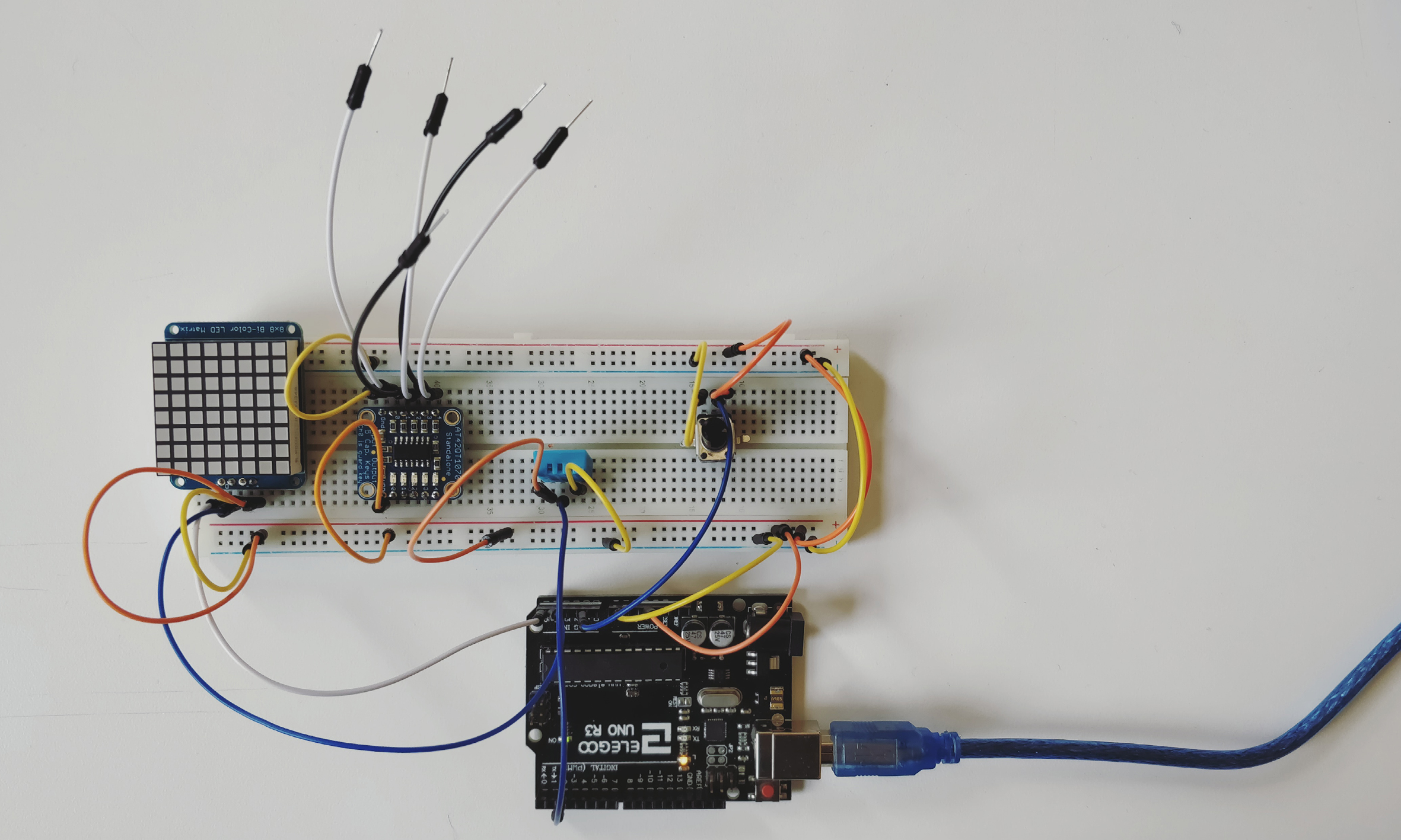
Using the standalone 5- pad capacitive touch sensor breakout. This particular component is really interesting. It does not need to be operated via a micro-controller and functions well by itself. The wiring is really simple- the details of which are available on https://www.adafruit.com/product/1362. After having worked on capacitive sensing a few weeks back, I was surprised at the sensitivity and level of precision this board provided.
Next steps: I want to connect the board to other outputs- like motors/ LED’s to see how it will work
Trial 4
Another component that I have had for a long time but never had a chance to use is the 8*8 Bicolor LED matrix. The wiring is standard and is included on the site. The matrix can be programmed to show different graphical outputs.
Next steps and questions: Could a programme translate a drawing that the user makes into coordinates that could be displayed on a matrix? Can multiple matrices display different portions of the same “sketch”?
While taking the video, I realized that taking a close up of the LEDs gives very interesting visual results.
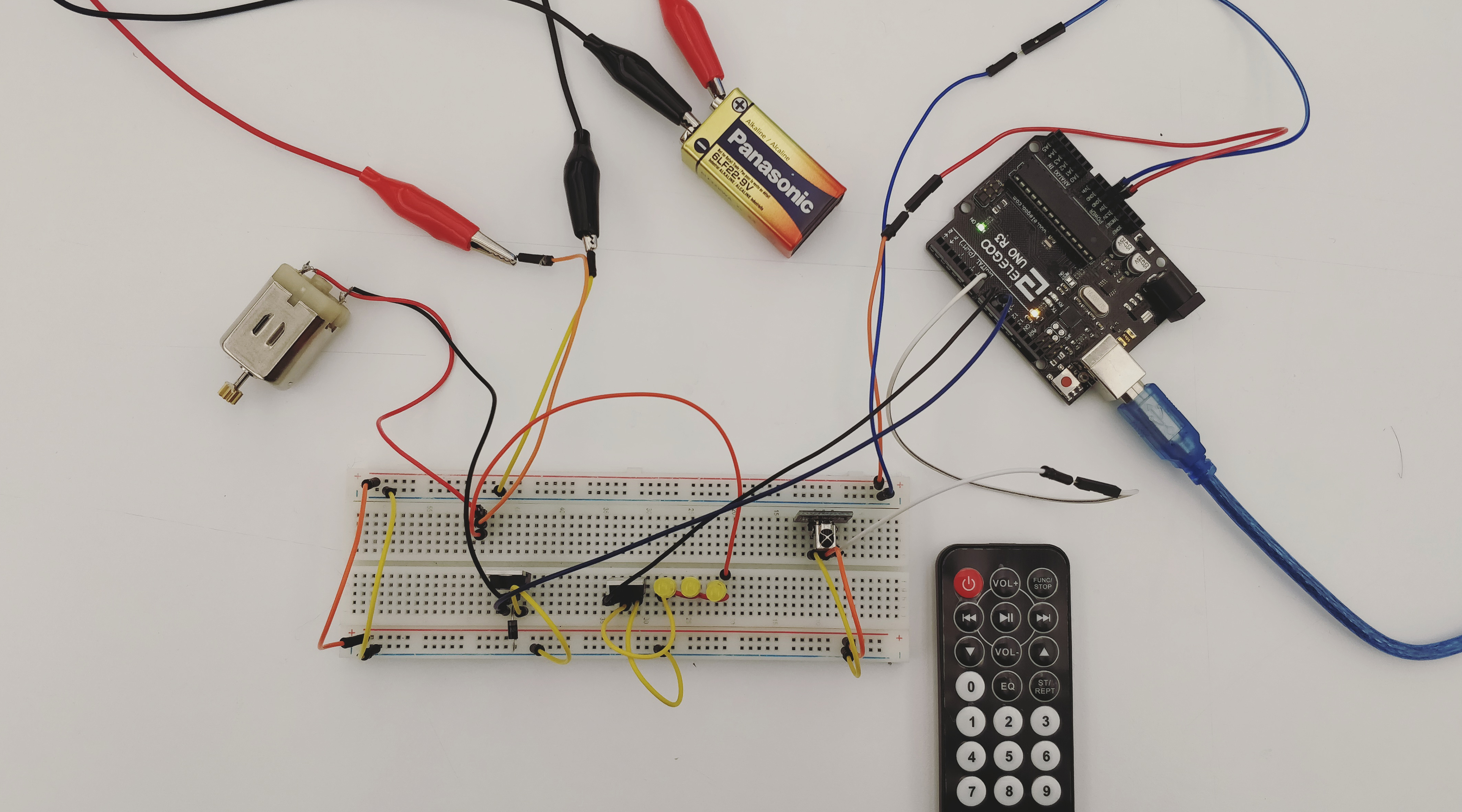
This week’s assignment was to use one of the wireless technologies we had learned in class and apply it to an everyday scenario. I decided to make a remote- controlled smart room of sorts, where one could control a tube light (string of LEDs) and fan (DC motor). This was done using the example code that we did in class. For the second part, I wanted to use the Arduino Uno as the Arduino Leonardo, and operate these devices through the keypad. This turned out to be more challenging than I had anticipated and did not work out.
The part that I got right
I was able to get the circuit to work by combining the IR sensor circuit with the circuit for controlling high current loads using an Arduino. The setup works when one uses a remote control, and I can control the LEDs and motor independently, but also run them together using the available power.
The part that did not work
Operating the circuit through the laptop keypad so that on pressing different buttons the different components would run.
What did I learn
To use recent tutorials. A lot of the documentation around this topic is from around six years ago. I tried, unsuccessfully, to follow along with the tutorials only to realize that the hardware or the software had been modified/ was no longer in use.
I realized the immense potential of the Arduino. For someone who is familiar with its inner workings, it gives a lot of room for experimentation.
The importance of weighing in multiple factors before starting the project. The functionality that I was trying to recreate using the Arduino Uno is inherently present in the Leonardo. Moving forward, I will look at the time, effort, resources and cost involved in the process before choosing it over another alternative.
This week’s assignment was to creatively rethink how sound and/or light could be incorporated into projects by modifying the input sensors. I decided to work with capacitive sensing because I love the possibilities it provides. It allows us to make our own sensors and enhances the quality of the interactive experience.
List of Materials
1 x Elegoo Uno R3
1 x Full sized breadboard
1 x Piezo buzzer
3 x Graphite strips
3 x LEDs
Resistors: 3x 220 Ohms (for the LED), 3 x 1 Megaohms (for capacitive sensing)
Jumper wires
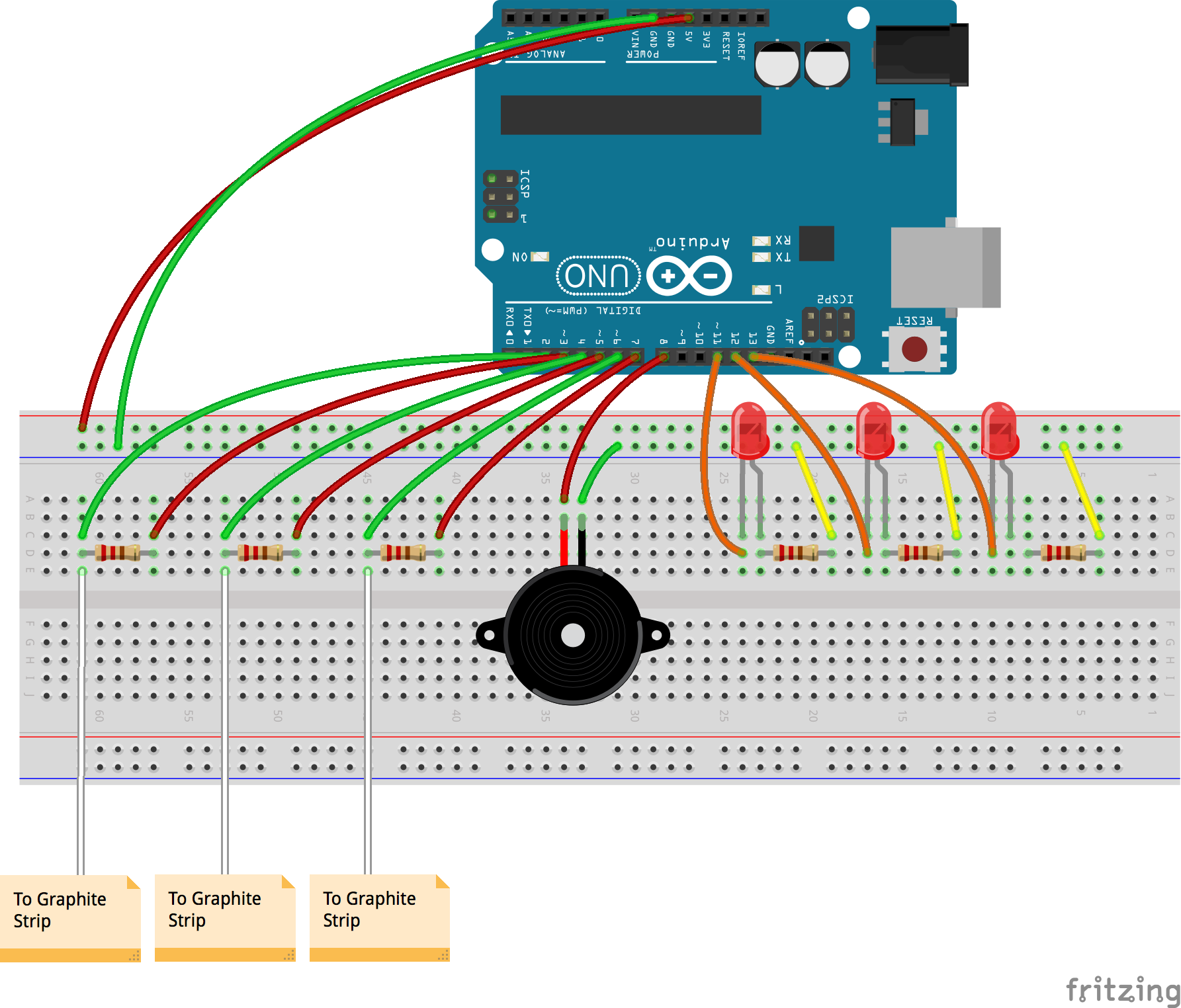
Fritzing diagram
Description of assembly
Connect the ground side of the breadboard to the GND pin, and the power side to the 5V pin, on the Arduino.
Add three LEDs to the circuit, with the shorter legs connected to the ground via 220 Ohm resistors, and the longer legs to digital pins 11, 12 and 13 respectively. Connect the Piezo buzzer with the ground connected to the ground of the breadboard, and the power to digital pin 8. Both the LEDs and the buzzer act as the output, reacting to changes in the capacitive sensors.
To make one capacitive sensor, connect two jumper wires on either end of a 1 Megaohm resistor to digital pins 2 and 3. The resistor leg, connected to pin 2, should also be connected through the jumper wire to the graphite strip.
Repeat step 3 two more times, using digital pins 4, 5 and 6,7.
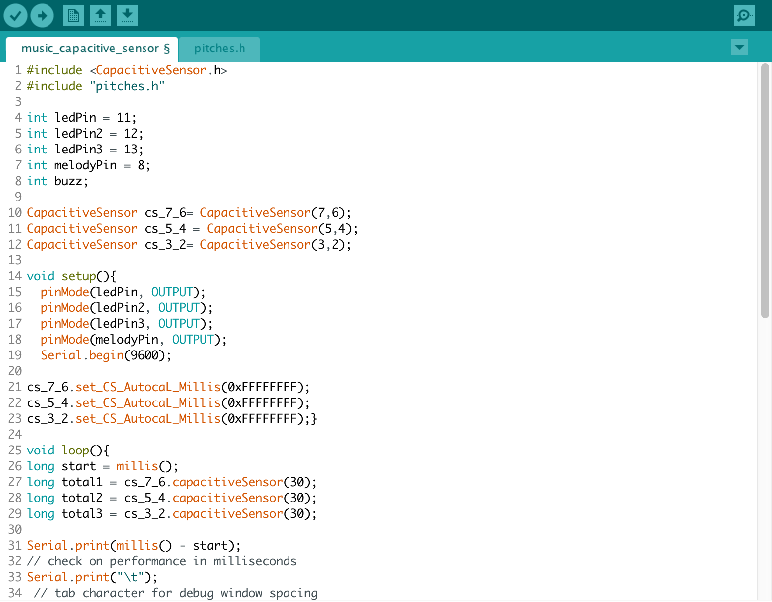
Upload the code to the Arduino IDE.
Debug, check connections and keep working!
How it works
Capacitive sensing works on the principle of using a conductive material to complete the circuit. This circuit works as follows. A high resistance of the order of a megaohm is placed on the breadboard, both ends of which are connected to say, digital pins 2 and 3. Digital pin 3 acts as the input and allows a steady stream of electrons to flow through the circuit. The resistor inhibits the flow and only lets a small number of electrons pass through the other end. The other end in addition to being connected to a digital pin is also attached to a jumper wire. When we touch the metallic end, we pass on a large number of electrons from our body to the circuit. The Arduino can sense this change and can be coded to control an output by defining a threshold value.
Iterations
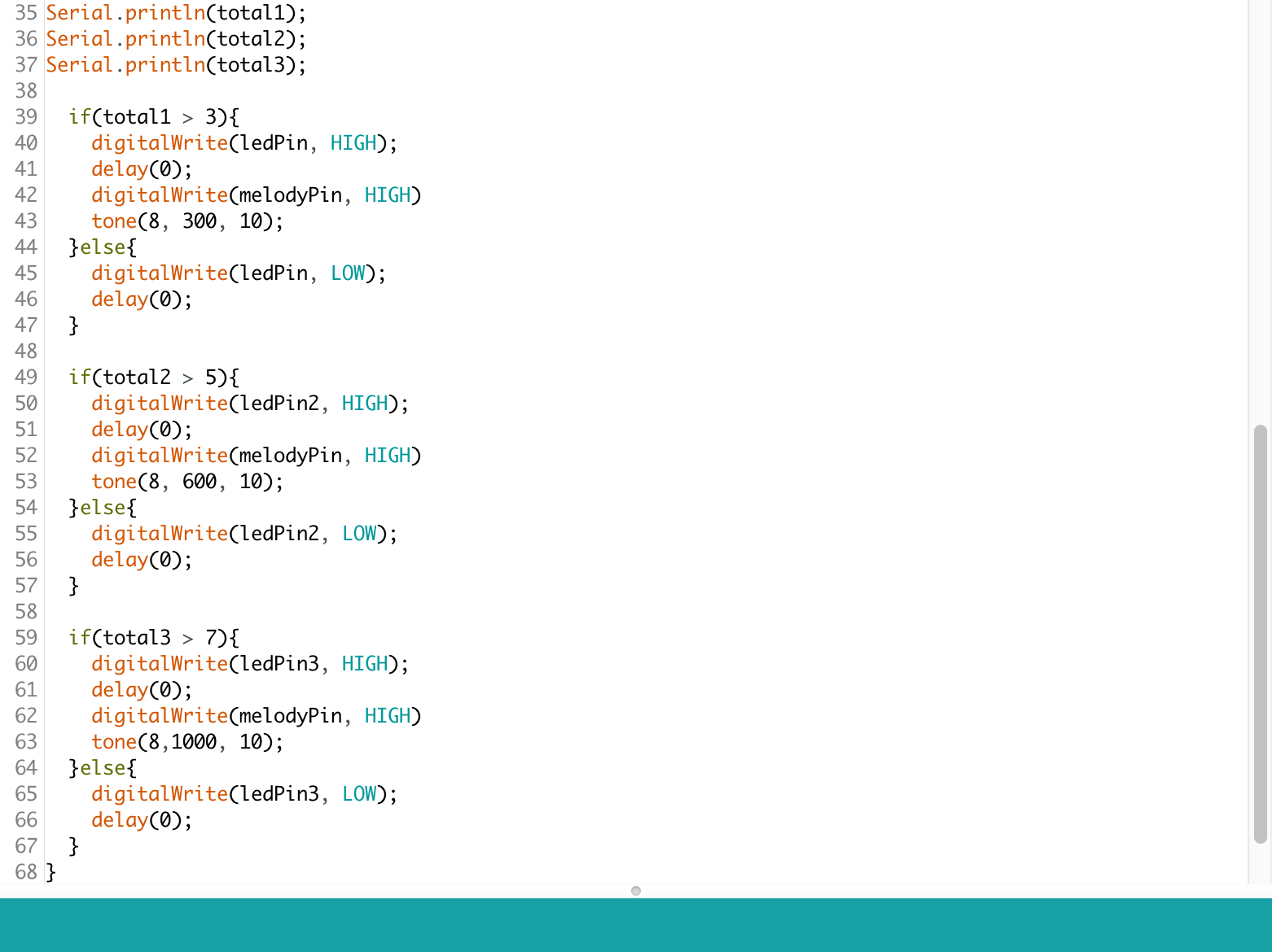
Graphite conducts electricity and this property can be utilized in interesting ways. I shaded some bits of paper with an HB pencil and connected them to the breadboard so that they could act as switches. For the first iteration I decided to make an instrument where, on pressing each key, one would hear a different, pre-programmed song through the Piezo buzzer. I first tried with the example code melody to see whether all three switches were working individually. On graduating to coding different songs, I had limited success.
This further led me to think about how a user could make their own music. On pressing a key, they would hear a tone, akin to a piano. The various sequences and combinations could culminate in unique tunes. I had trouble associating one LED to one graphite switch. After multiple iterations, it turned out to be a glitch in the code which I then rectified.
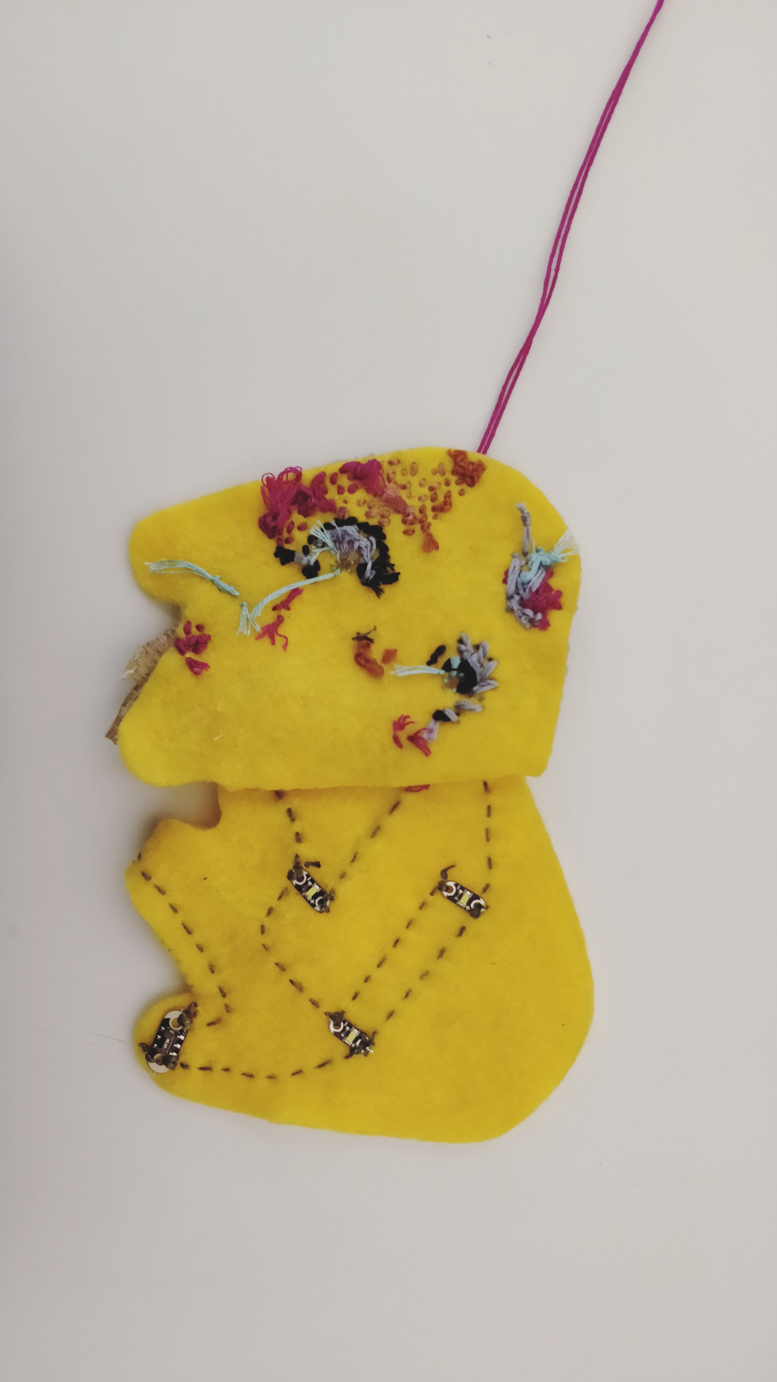
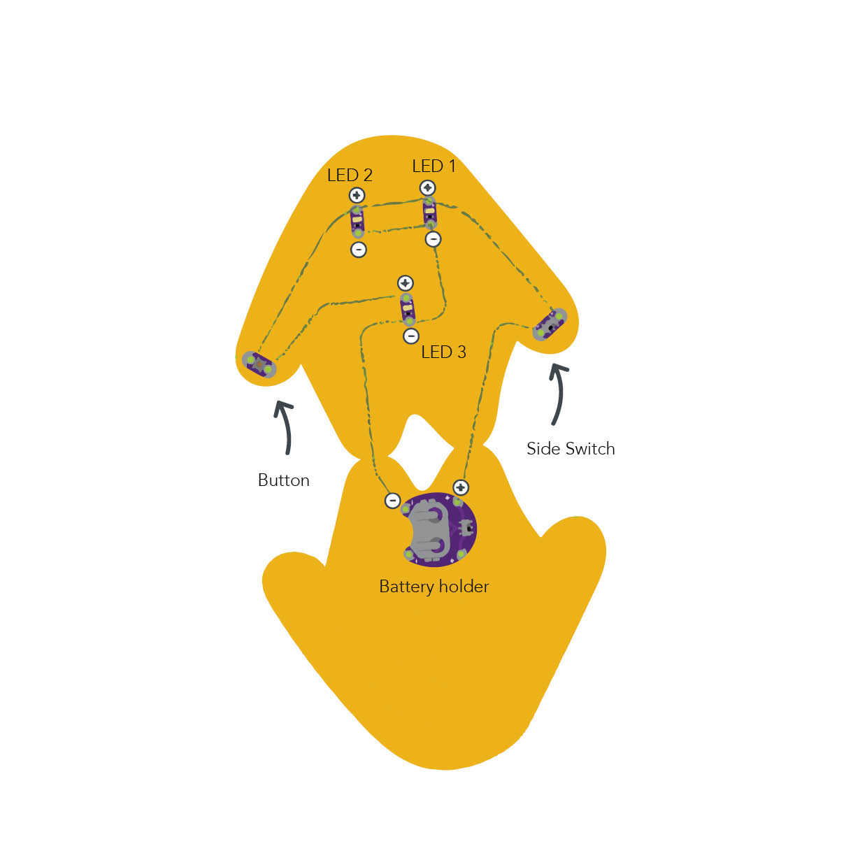
For a very long time, I have been fascinated by e-textiles because they lie at the intersection of craft and electronics. I did not know where to begin my exploration from and decided to follow along a simple Sparkfun tutorial to make a light-up plush (https://learn.sparkfun.com/tutorials/light-up-plush)
Materials required
Lilypad ProtoSnap
3V Coin Cell Battery
Conductive thread
Needle
Plush pattern
Felt piece: 10 by 10 inches
Scissors
Fabric glue (optional)
Beads, pompoms, ribbons, buttons, glitter to decorate
Diagram (taken from the Sparkfun website)
Description of assembly
Cut the plush pattern from the piece of felt
Arrange the Lilypad ProtoSnap components on the pattern.
Using conductive thread, make secure connections (loop around each tab at least 3-4 times) between the positive tab of the battery holder and one of the tabs of the switch.
Connect the other side of the switch to the positive terminals of the top two LEDs that make up the eyes, and finally to one of the tabs of the button.
Continue stitching, from the other side of the button to the positive tab of the last LED.
Connect the negative sew tab of the first LED, with the second, through the third to the negative sew tab of the battery holder.
Insert the battery, debug, and keep experimenting!
How it works
I was surprised to find that working with e-textiles isn’t very different from working with the Arduino hardware. It is based on the same principles of electronics that we are familiar with. A 3V coin cell powers the circuit, and the electrons, regulated through the side switch and the button, light up the LEDs.
Challenges
I had difficulty debugging my circuit. Unlike a “traditional” circuit, it was time-consuming to check the connections- as I had to re-embroider entire sections. Later I realized, that my circuit was getting shorted because of the long, untrimmed pieces of wire. After securing a few connections, and trimming the ends, it started working!
Future Iterations
I am excited about incorporating physical elements or characters in the process of digital storytelling. I feel they make the story more compelling. I was imagining a choose-your-own-adventure story, that plays out on the screen, depending on one’s choices in the real world. So these characters could act as controllers that are affecting the narrative. Continue reading →
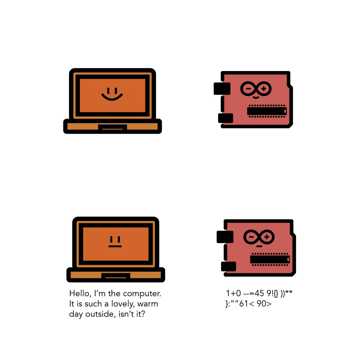
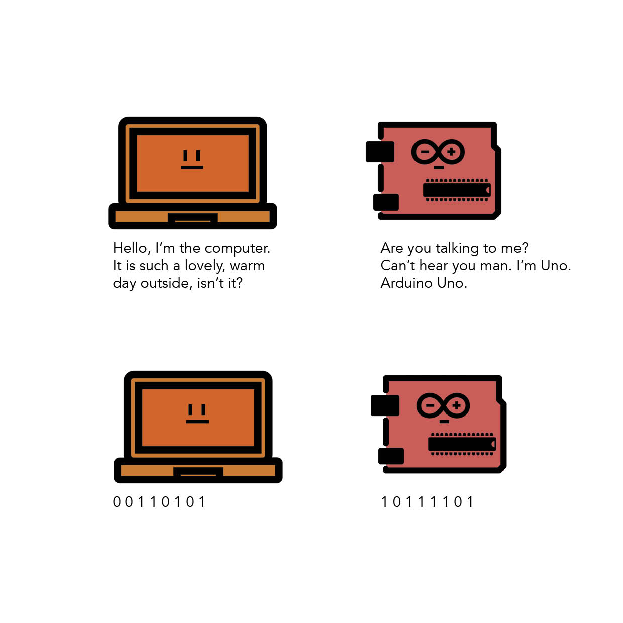
Electronics are all about interlinking individual circuits to create a larger system. In order for the individual circuits to exchange information/ “talk” with each other it is important that they speak the same language (or technically speaking share a common communication protocol).
Just as we have developed languages that we use for communication, electronic circuits speak in the binary language- a long string of information- made up of only 0’s and 1’s.
But even when they speak the same language, they should have a channel of communication between them (Think of it as the air that helps us talk to each other by transferring the vibrations caused by sound waves). There are hundreds of communication protocols that help circuits talk to each other. They can be broadly categorized into parallel or serial communication protocols.
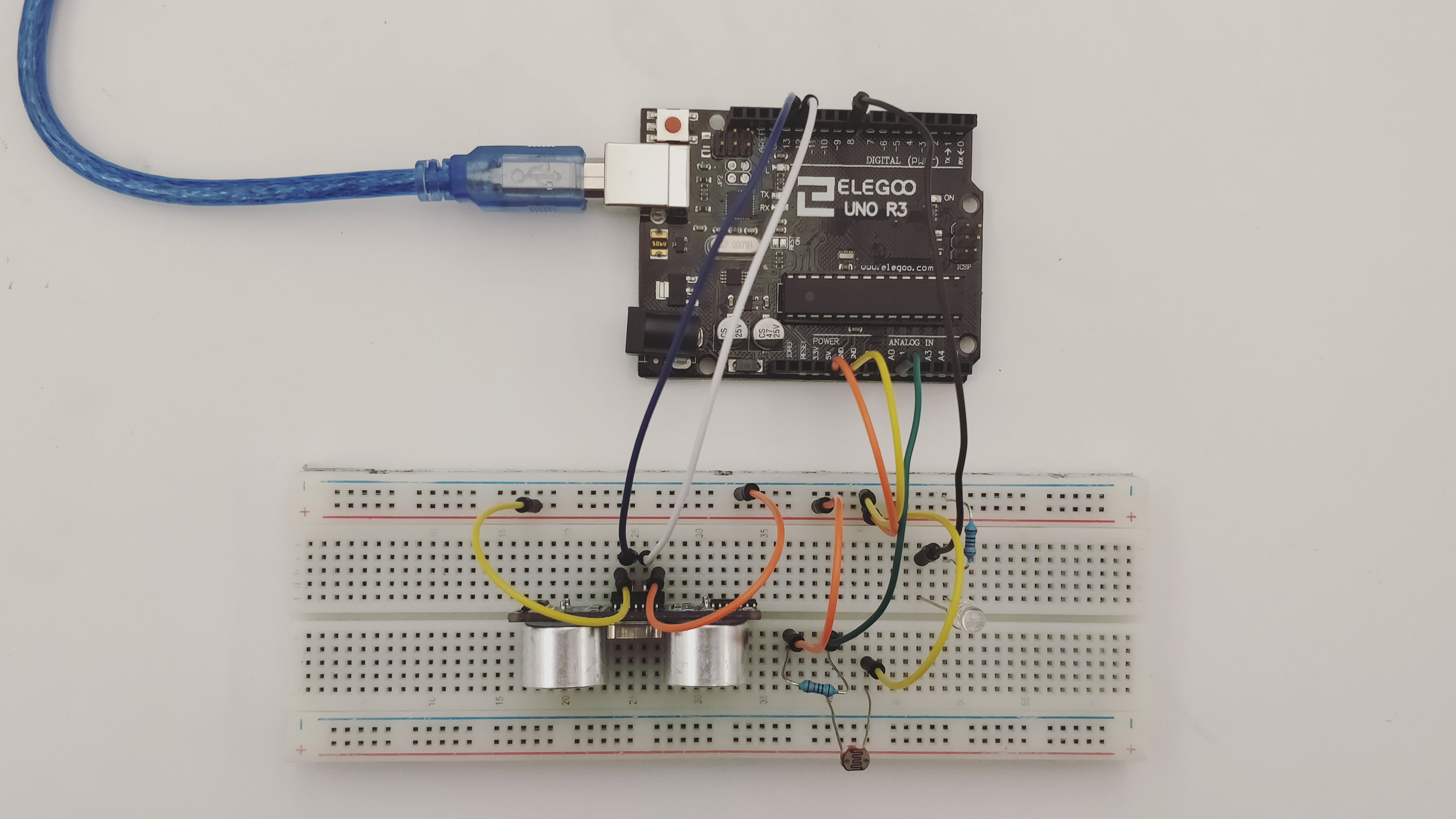
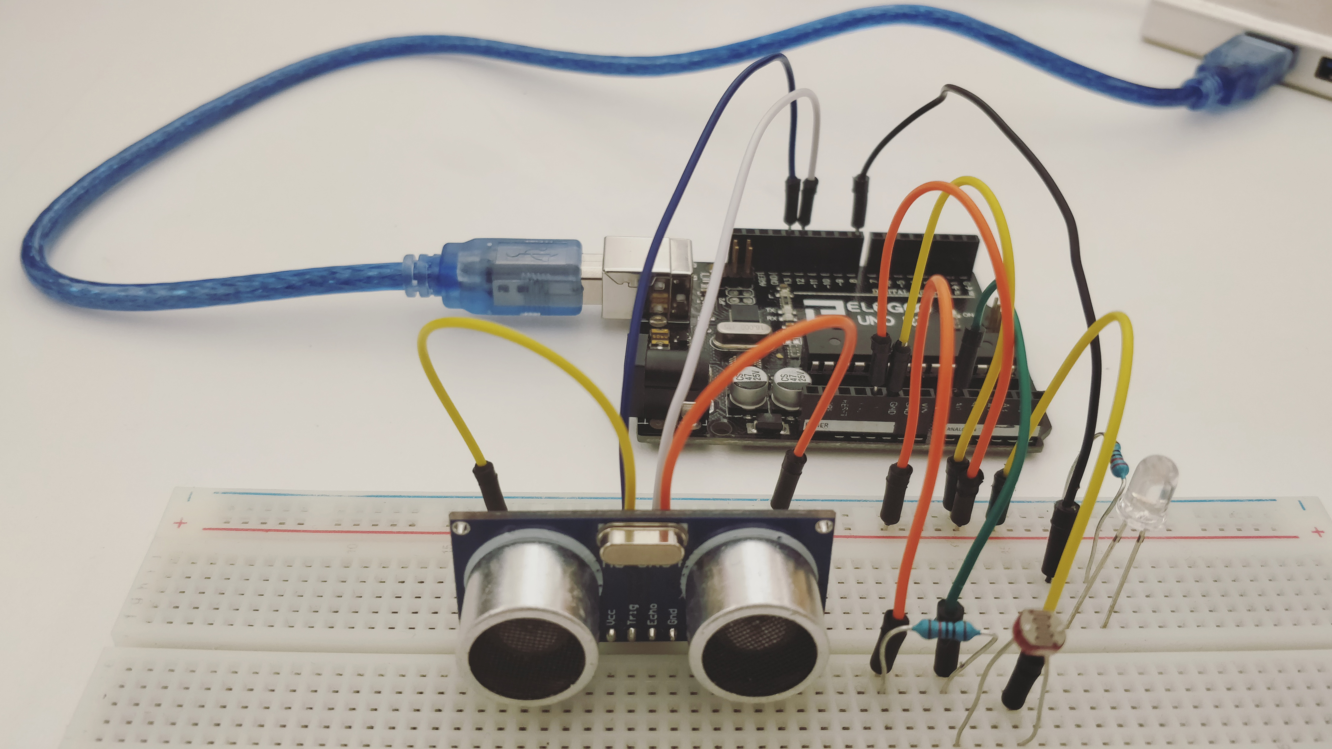
This week’s assignment was to create a circuit, where an ultrasonic sensor and a photosensor are used to control the state of the LED. Only when certain conditions are met for both, does the LED turn on.
List of Materials
1 x Elegoo Uno R3
1 x Full sized breadboard
1 x HC-SR04 Ultrasonic sensor
1 x Photocell (or photoresistor)
1 x LED
Resistors: 1x 220 Ohms (for the LED), 1 x 10K Ohms (for the photocell)
Jumper wires
Description of assembly
Connect the ground side of the breadboard to the GND pin, and the power side to the 5V pin, on the Arduino.
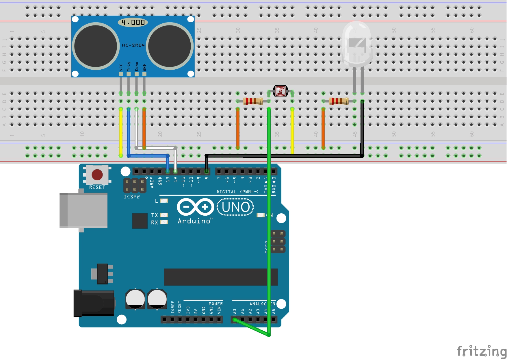
Place the Ultrasonic sensor on the breadboard. Connect the VCC pin to the power, the trig and echo pins to digital pins 13 and 12 respectively, and the GND pin to the ground. Then connect the photoresistor, with one of the legs connected to power, and the other to the ground (through a 10K Ohm resistor) and to the Analog Input Pin A0.
Finally, add an LED to the circuit, with the shorter leg connected to the ground via a 220 Ohm resistor, and the longer leg to digital pin 8.
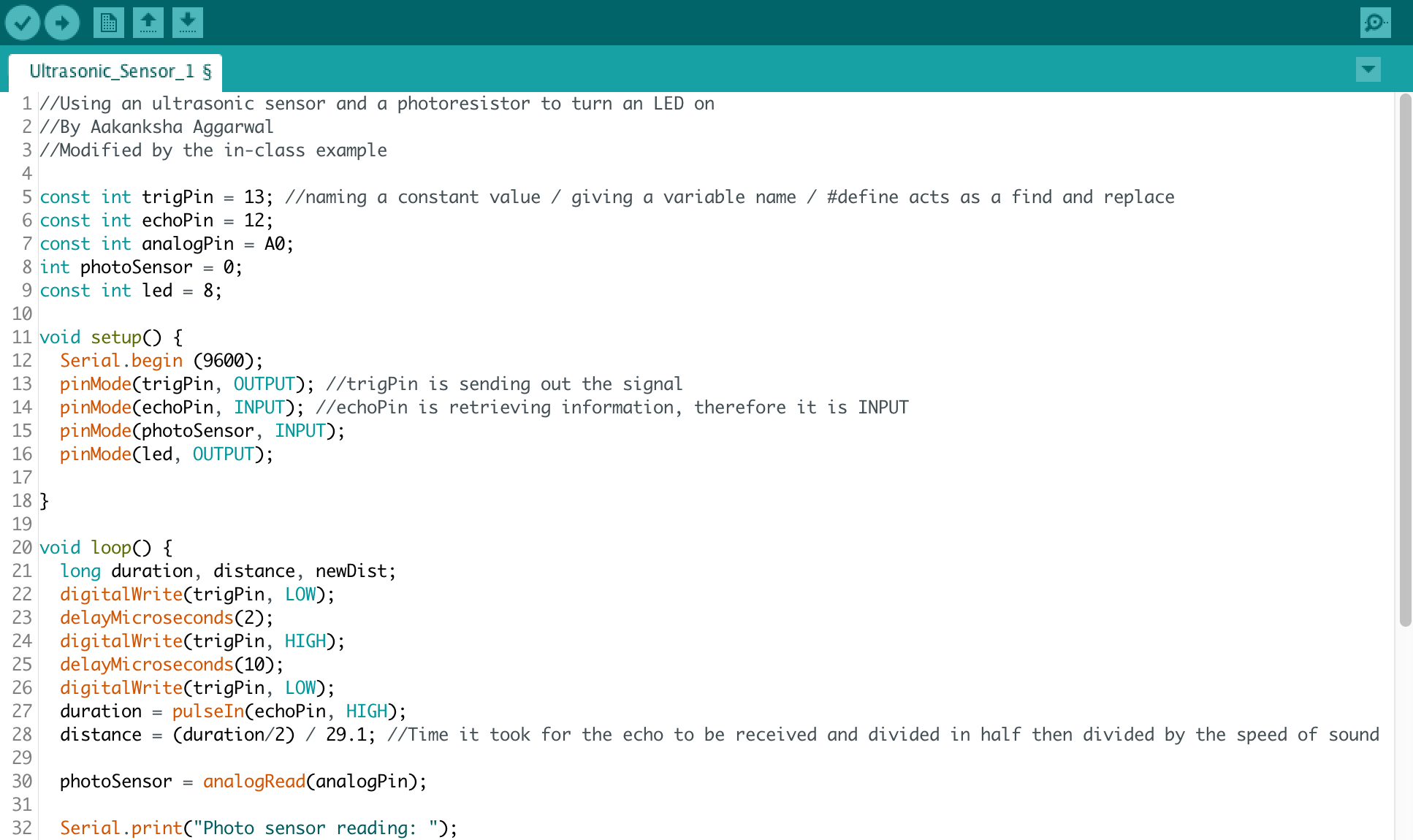
Upload the code to the Arduino IDE.
Debug, check connections and keep working!
Fritzing Diagram (Using the open source, free software available at http://fritzing.org)
How it works
The code has an if statement that checks for two conditions- the proximity of the object from the ultrasonic sensor and the amount of light entering the photocell. Only when BOTH the conditions are satisfied, does the LED turn on. In all other cases, it remains off.
Challenges
Initially, I was having a problem with adjusting the threshold values for the two analog sensors. With the help of the serial monitor, I was able to choose the appropriate value.
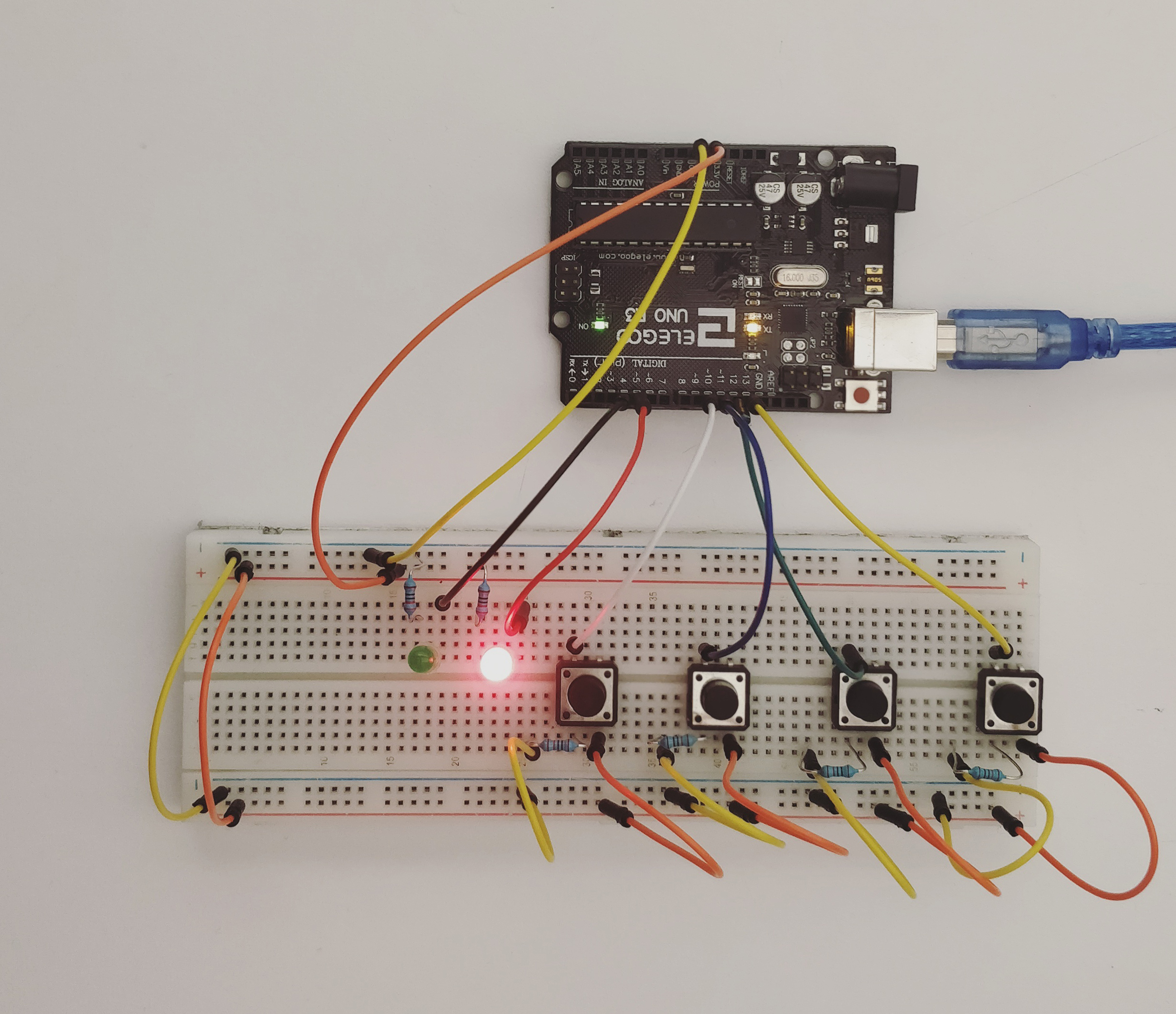
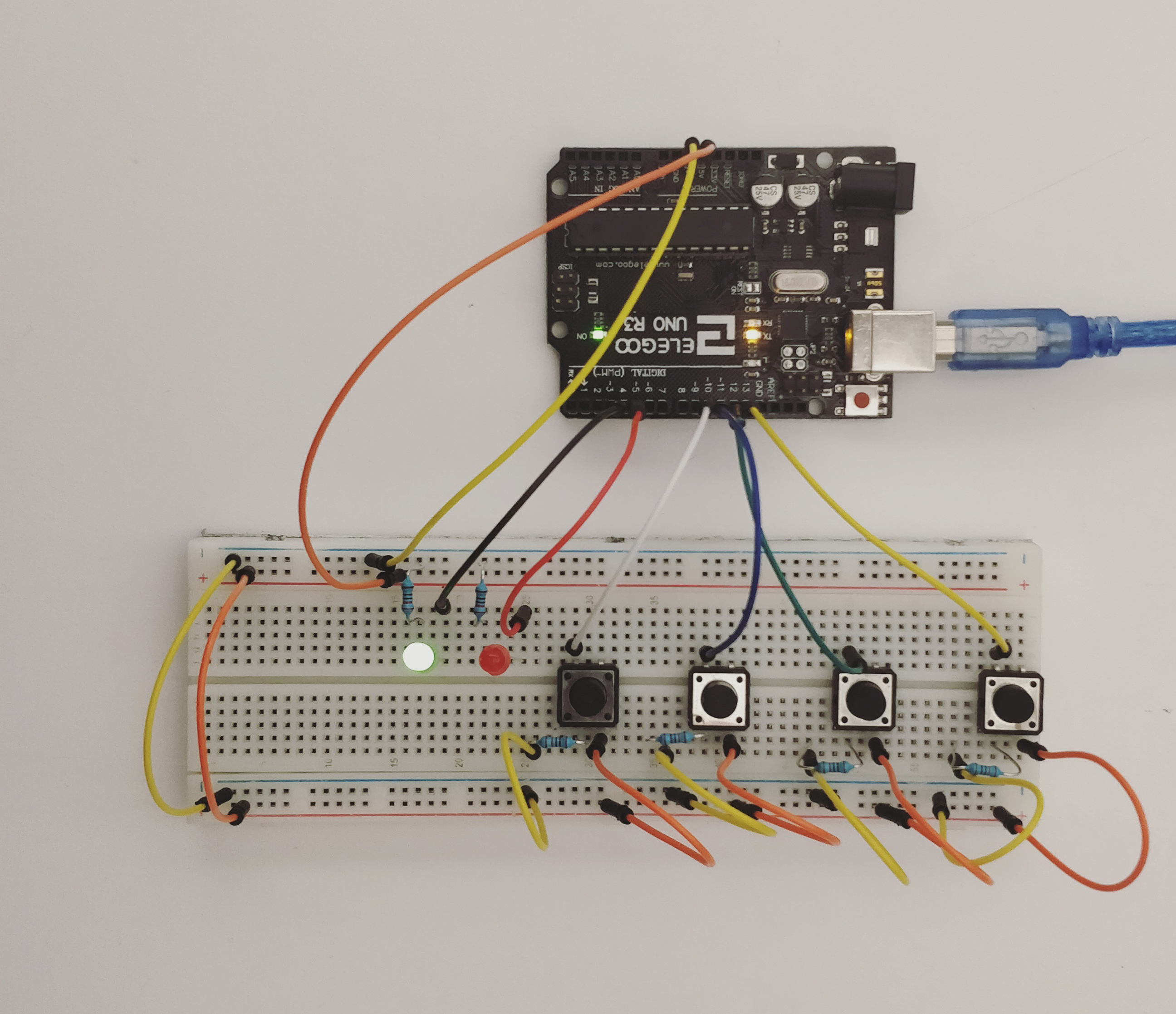
This Week’s assignment was to create a circuit for a combination lock. The default state for this circuit is locked (represented by a red LED). When all four buttons are pressed in the right sequence, the circuit becomes unlocked (LED turns green).
List of Materials
1 x Elegoo Uno R3
1 x Full sized breadboard
4 x Pushbuttons
2 x LED’s (Red and Green)
Resistors: 4 x 220 Ohms (for the LEDs), 2 x 10K Ohms (for the buttons)
Jumper wires
Description of assembly
Connect both sides of the breadboard to each other. The ground to the ground and the power to the power using jumper wires.
Connect the ground side of the breadboard to the GND pin, and the power side to the 5V pin, on the Arduino.
Add pushbuttons to the breadboard, where one of the legs is connected to the power source, the adjacent leg to the ground (through the resistor). Connect the leg opposite the ground to a digital pin. When the pushbutton is not pressed, the digital output pin is connected to the ground and returns a LOW state. When it is pressed, the circuit gets complete, electricity flows through it, and a HIGH state is recorded.
Arrange the LEDs with the shorter leg connected to the ground through a resistor and the longer leg to the digital pins.
Upload the code to the Arduino IDE.
Debug, check connections and keep working on iterations.
How it works
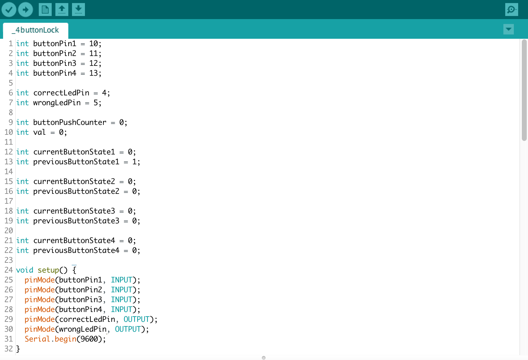
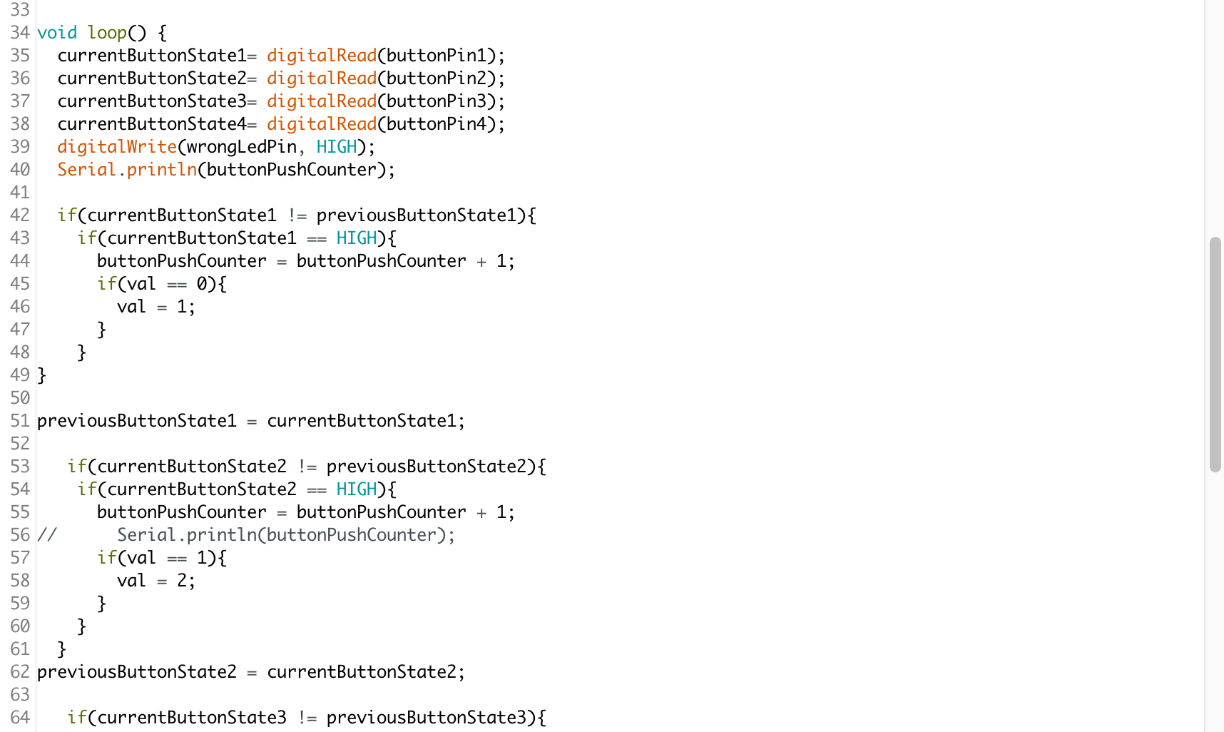
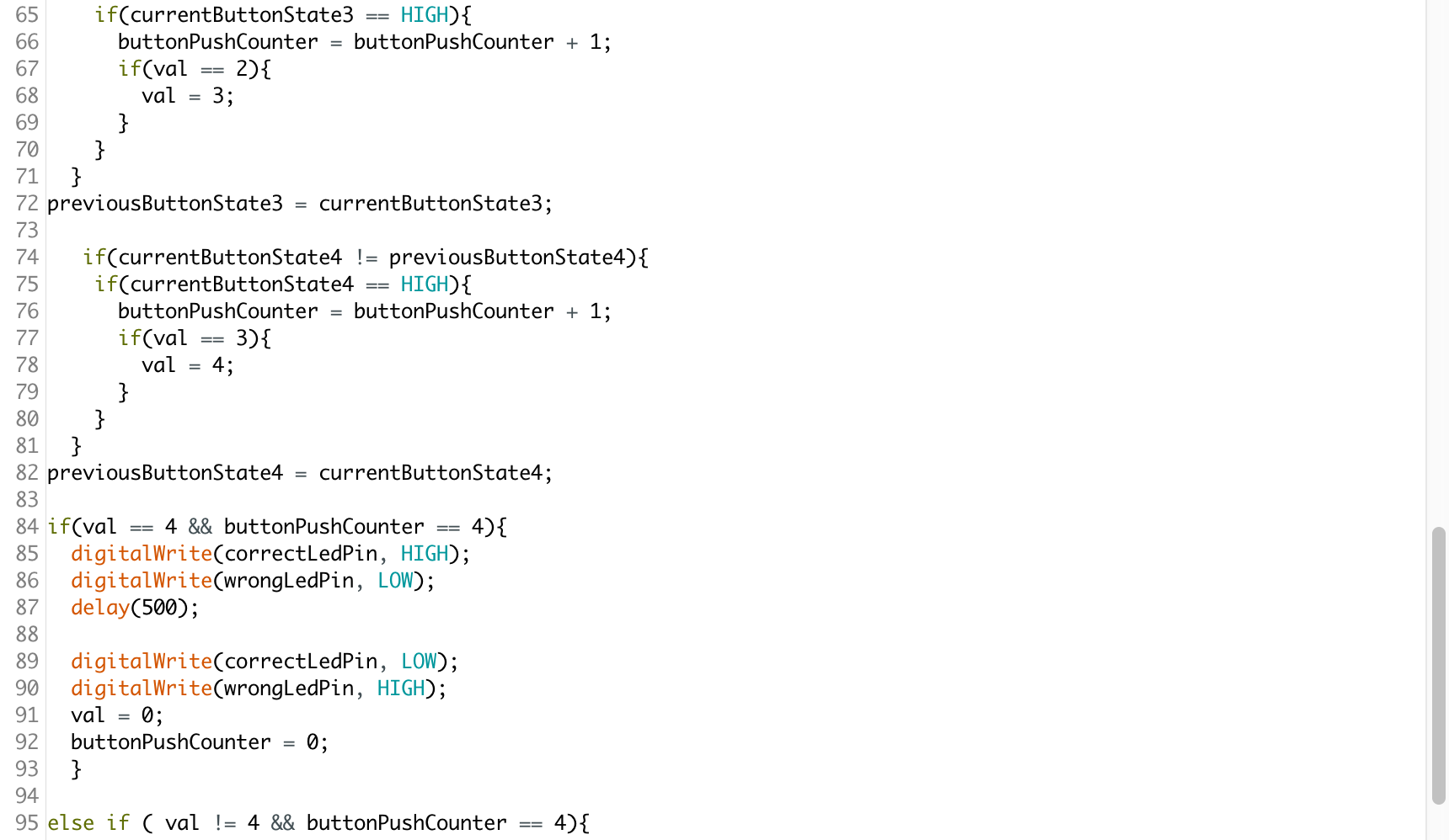
The Arduino code, has nested if loops that sequentially check whether certain conditions hold true. It first checks whether button 1 is pressed, if it is, then it checks if button 2 is pressed and so on and so forth. There are two variables being used buttonPushCounter and val. The first checks whether any button is being pressed and the other is to determine the order in which they are being pressed. It is only when all the four buttons are pressed in the right order that the green LED lights up.
Challenges
Setting the circuit was not as challenging as was getting the code to work. I encountered a problem with my buttonPushCounter because it wasn’t registering button presses. I used the console to debug and realized that it was because I had defined the variable globally as well as locally which was interfering with the functioning of the code. The solution is to either define it globally or to use something called static int to define it within the scope of the void loop.
What I am still struggling with is using the same button twice in the code. At present, I can program different combinations of button presses, but I cannot get the counter to reset every time a button is pressed.
Code
//Referenced from code available on the Arduino forum
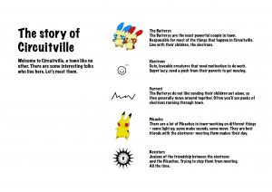
Team members:
Aakanksha Aggarwal, Elizabeth Ho, Joyce Zheng
We wanted to explain the differences between a series and parallel circuit (in terms of the Current flow, Voltage distribution, and resistance) in a fun, and engaging way. We thought that making a narrative, and introducing characters would be an effective way to introduce the differences to complete beginners.
One of the major takeaways for us was that we learned so much about this concept while trying to making a teaching aid. Also, it compelled us to think about the core ideas, the logic behind the working of circuits instead of the numerical or symbolic representations.