The goal of this assignment:
Create a circuit with ultrasonic sensor and photocell to fulfill the following requirements:
- If the environment is bright, the LED won’t light up.
- If the environment is dark but the distance is far away, the LED won’t light up.
- If the environment is dark and the distance is less than__, the LED will light up.
List of components:
- arduino Uno
- 220-ohm resistorx1 (led)
- 10k resistorx1 (photocell)
- photocellx1
- ultrasonic sensorx1
- wires and breadboard
How it works:
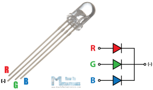
How photocell works is to change analog voltage based on the amount of light received by the sensor. As the light level increases, the analog voltage goes up even though the resistance goes down. For the ultrasonic sensor, using echo and trig pin to detect the soundwave and then calculate the distance between object. Put all together in this circuit, the photocell will detect the light amount in the environment at first, and if it’s bright enough (depend on each photocell, the number change dramatically because it’s super unstable) the led won’t light up. If the distance between the object(hand) and ultrasonic sensor is less than 10cm, the led will light up. However, even if you cover the whole photocell to make the environment dark, the led won’t light up because of the && function in code. You still need to be close enough to the distance sensor to make it work.
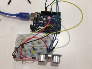
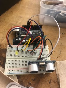
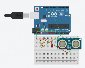
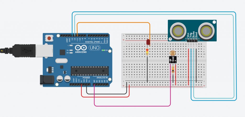
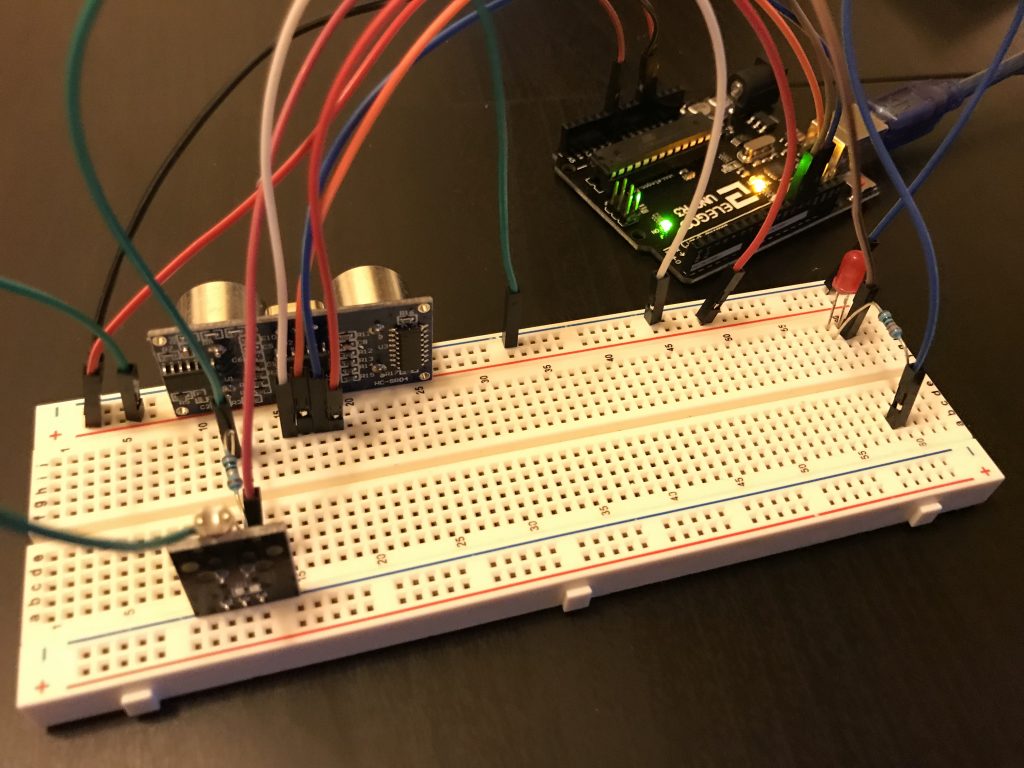
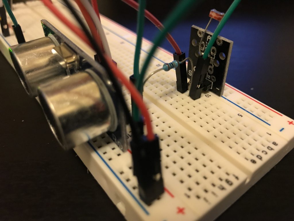
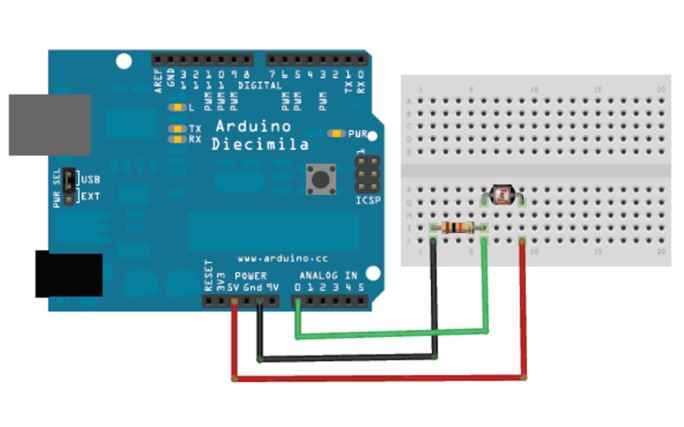
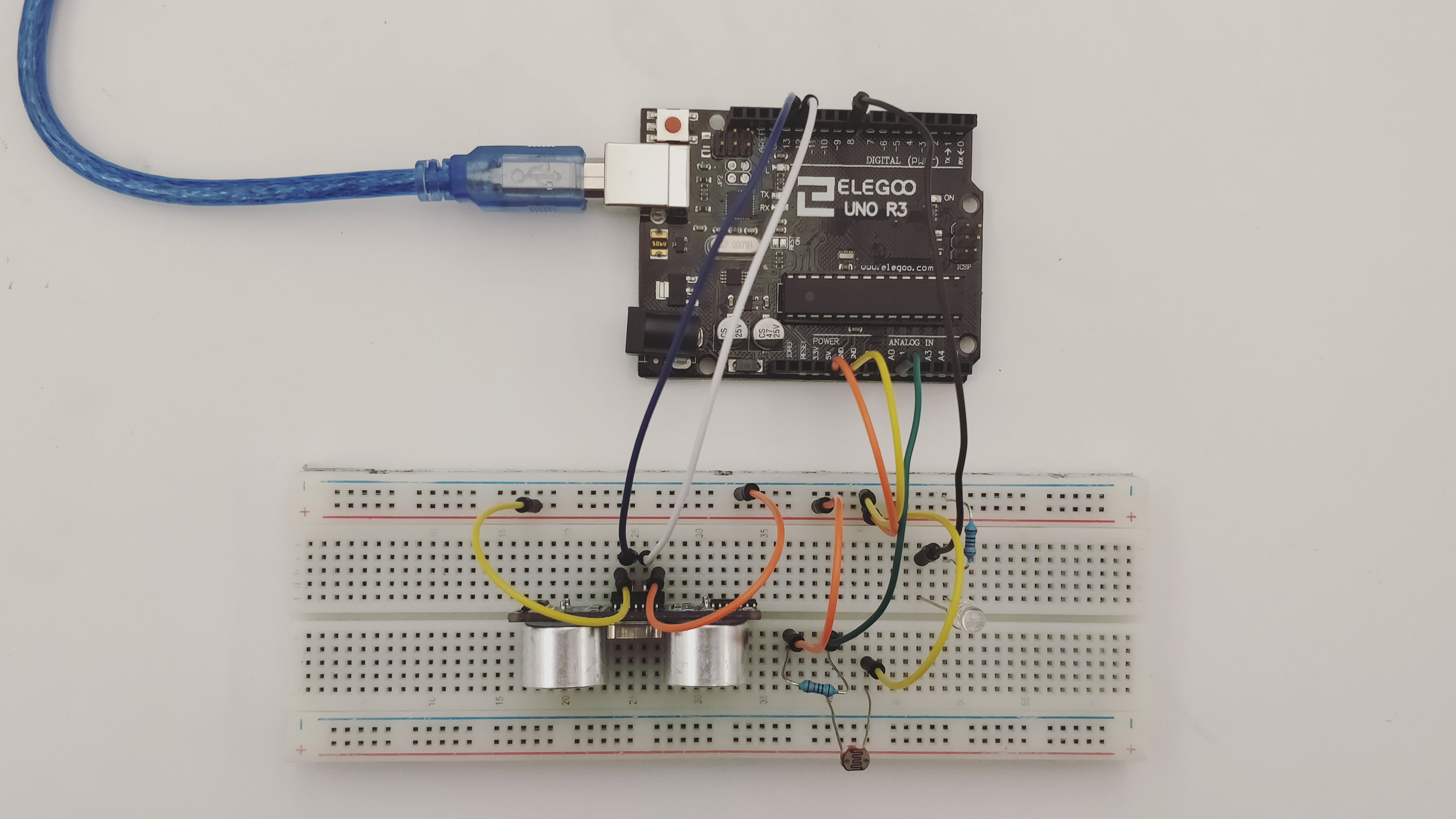
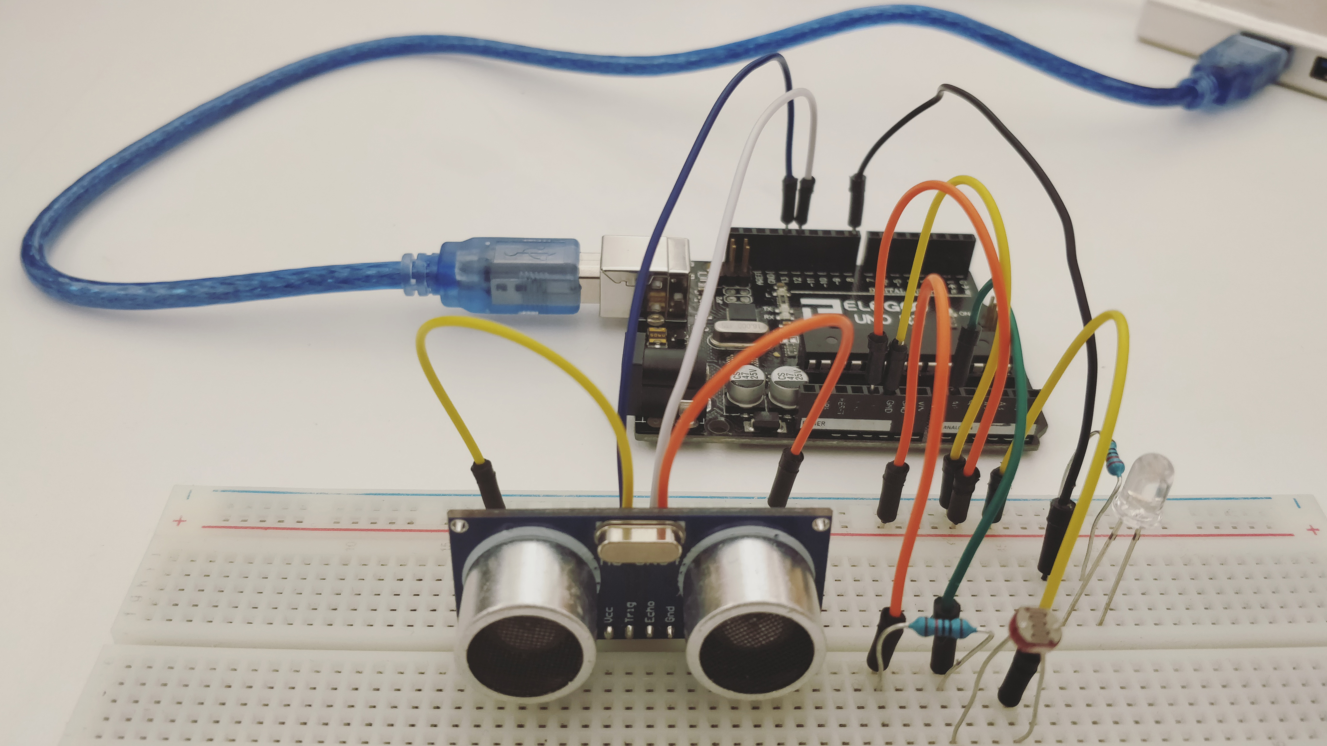
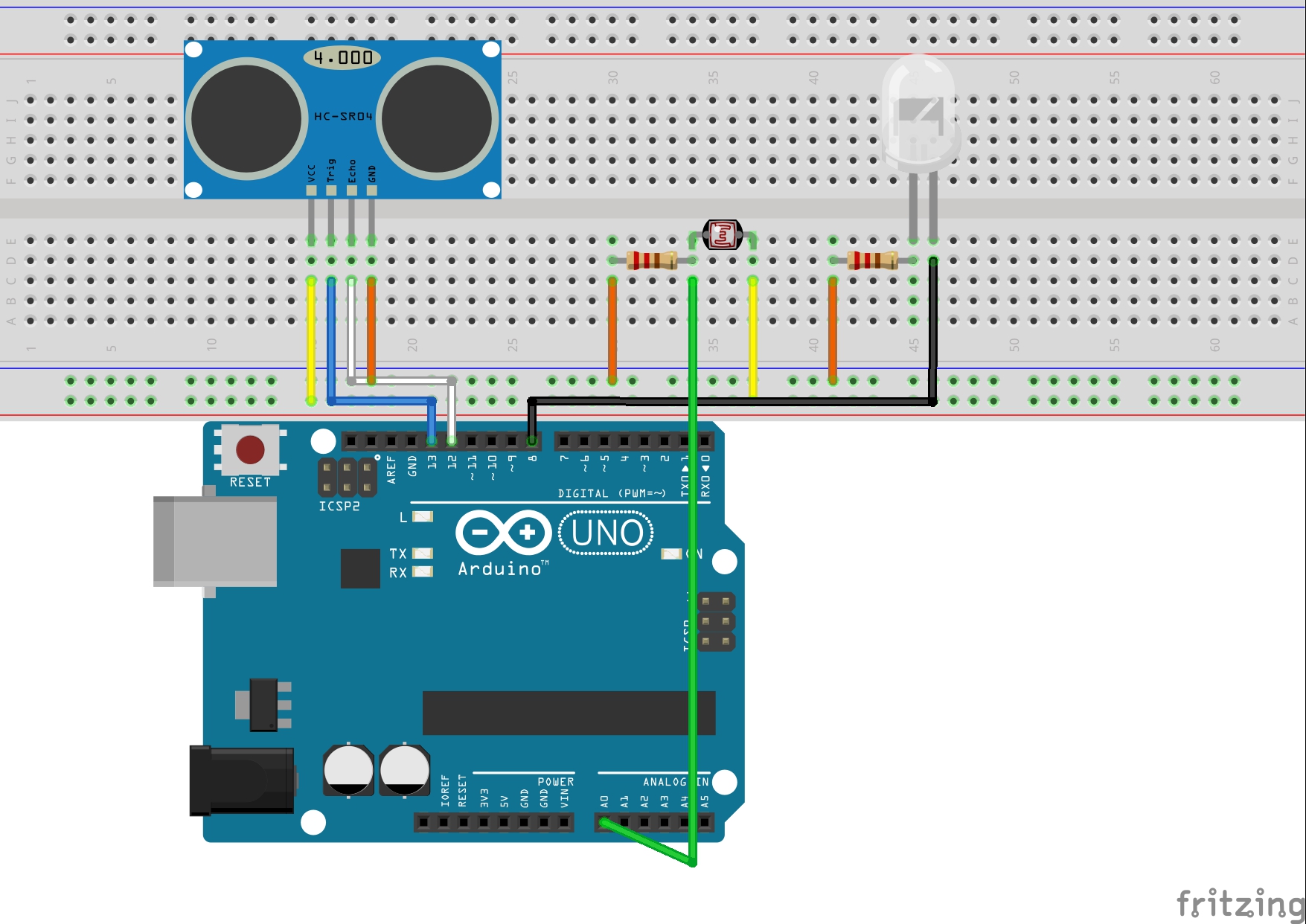
Circuit:

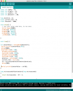
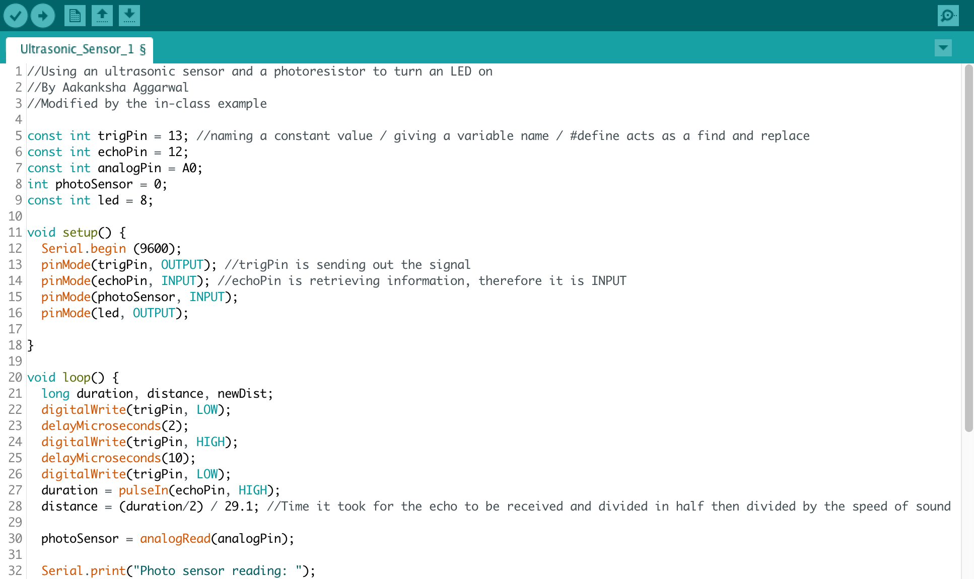
CODE in Arduino :
const int trigPin = 13; //naming a constant value / giving a variable name / #define acts as a find and replace
const int echoPin = 12;
const int yellowLed = 8;
const int photocell = A0;
int light;
void setup() {
Serial.begin (9600);
pinMode(trigPin, OUTPUT); //trigPin is sending out the signal
pinMode(echoPin, INPUT); //echoPin is retrieving information, therefore it is INPUT
pinMode(yellowLed, OUTPUT); //trigPin is sending out the signal
pinMode(photocell, INPUT); //echoPin is retrieving information, therefore it is INPUT
}
void loop() {
long duration, distance, light;
digitalWrite(trigPin, LOW);
delayMicroseconds(2);
digitalWrite(trigPin, HIGH);
delayMicroseconds(10);
digitalWrite(trigPin, LOW);
duration = pulseIn(echoPin, HIGH);
distance = (duration/2) / 29.1; //Time it took for the echo to be received and divided in half then divided by the speed of sound
light = analogRead(photocell);
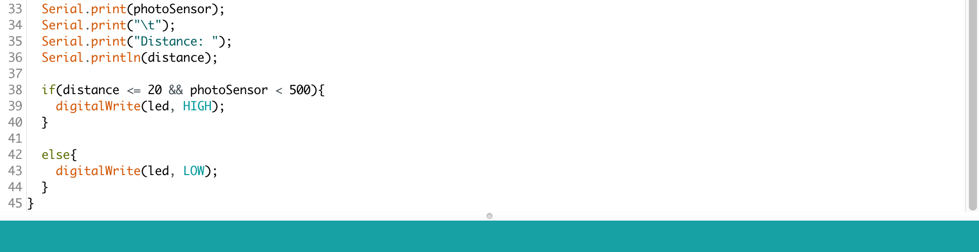
if(light < 700 && distance < 10){
// Serial.println(“work”);
digitalWrite(yellowLed, HIGH);
// wait for a second
}
else{
digitalWrite(yellowLed, LOW);
}
// Serial.print(distance);
// Serial.println(” cm”);
Serial.println(light);
// Serial.println(distance);
}
Problem:
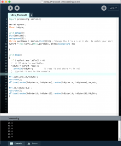
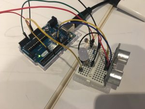
The photocell is really unstable, I tried connecting two different photocells at first, and kept getting 1023 in my serial monitor. Only after I moved to somewhere really bright and opened up the third brand new photocell then I got the reasonable number from the serial monitor.