This week’s assignment was to create a circuit, where an ultrasonic sensor and a photosensor are used to control the state of the LED. Only when certain conditions are met for both, does the LED turn on.
List of Materials
1 x Elegoo Uno R3
1 x Full sized breadboard
1 x HC-SR04 Ultrasonic sensor
1 x Photocell (or photoresistor)
1 x LED
Resistors: 1x 220 Ohms (for the LED), 1 x 10K Ohms (for the photocell)
Jumper wires
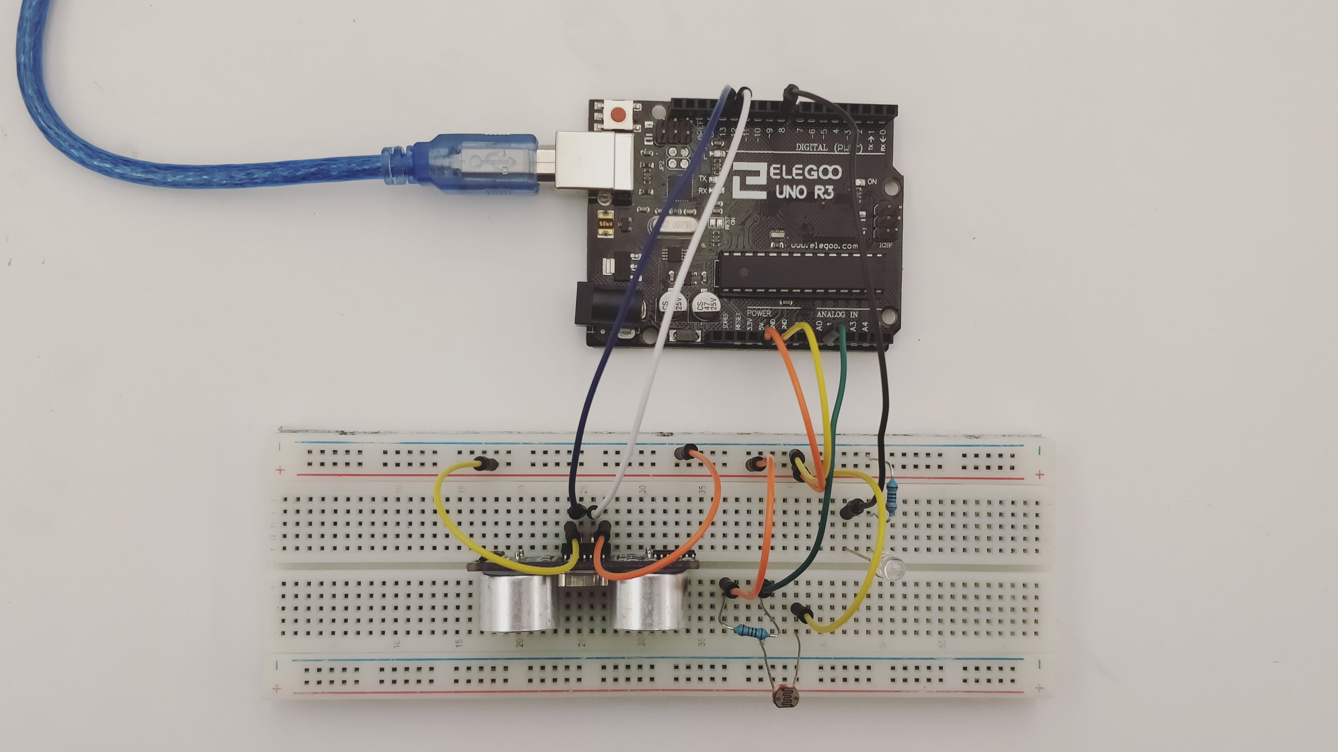
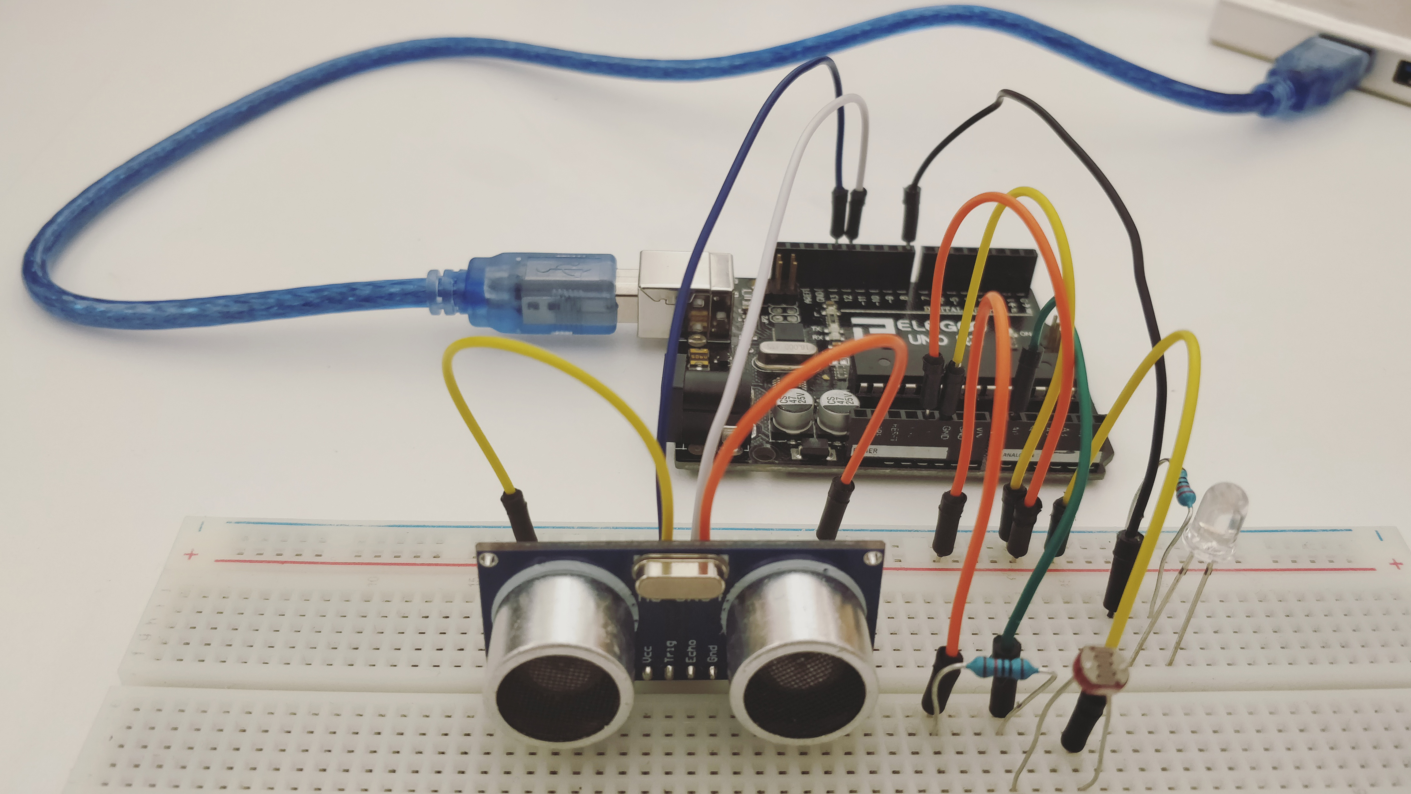
Description of assembly
- Connect the ground side of the breadboard to the GND pin, and the power side to the 5V pin, on the Arduino.
- Place the Ultrasonic sensor on the breadboard. Connect the VCC pin to the power, the trig and echo pins to digital pins 13 and 12 respectively, and the GND pin to the ground. Then connect the photoresistor, with one of the legs connected to power, and the other to the ground (through a 10K Ohm resistor) and to the Analog Input Pin A0.
- Finally, add an LED to the circuit, with the shorter leg connected to the ground via a 220 Ohm resistor, and the longer leg to digital pin 8.
- Upload the code to the Arduino IDE.
- Debug, check connections and keep working!
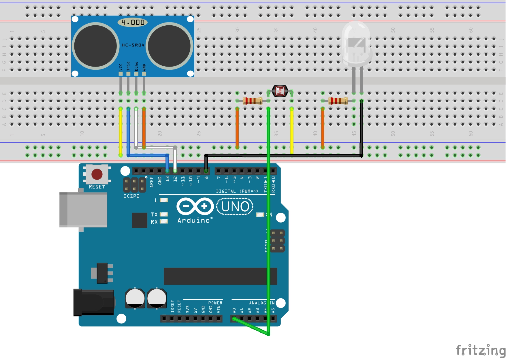
Fritzing Diagram (Using the open source, free software available at http://fritzing.org)
How it works
The code has an if statement that checks for two conditions- the proximity of the object from the ultrasonic sensor and the amount of light entering the photocell. Only when BOTH the conditions are satisfied, does the LED turn on. In all other cases, it remains off.
Challenges
Initially, I was having a problem with adjusting the threshold values for the two analog sensors. With the help of the serial monitor, I was able to choose the appropriate value.
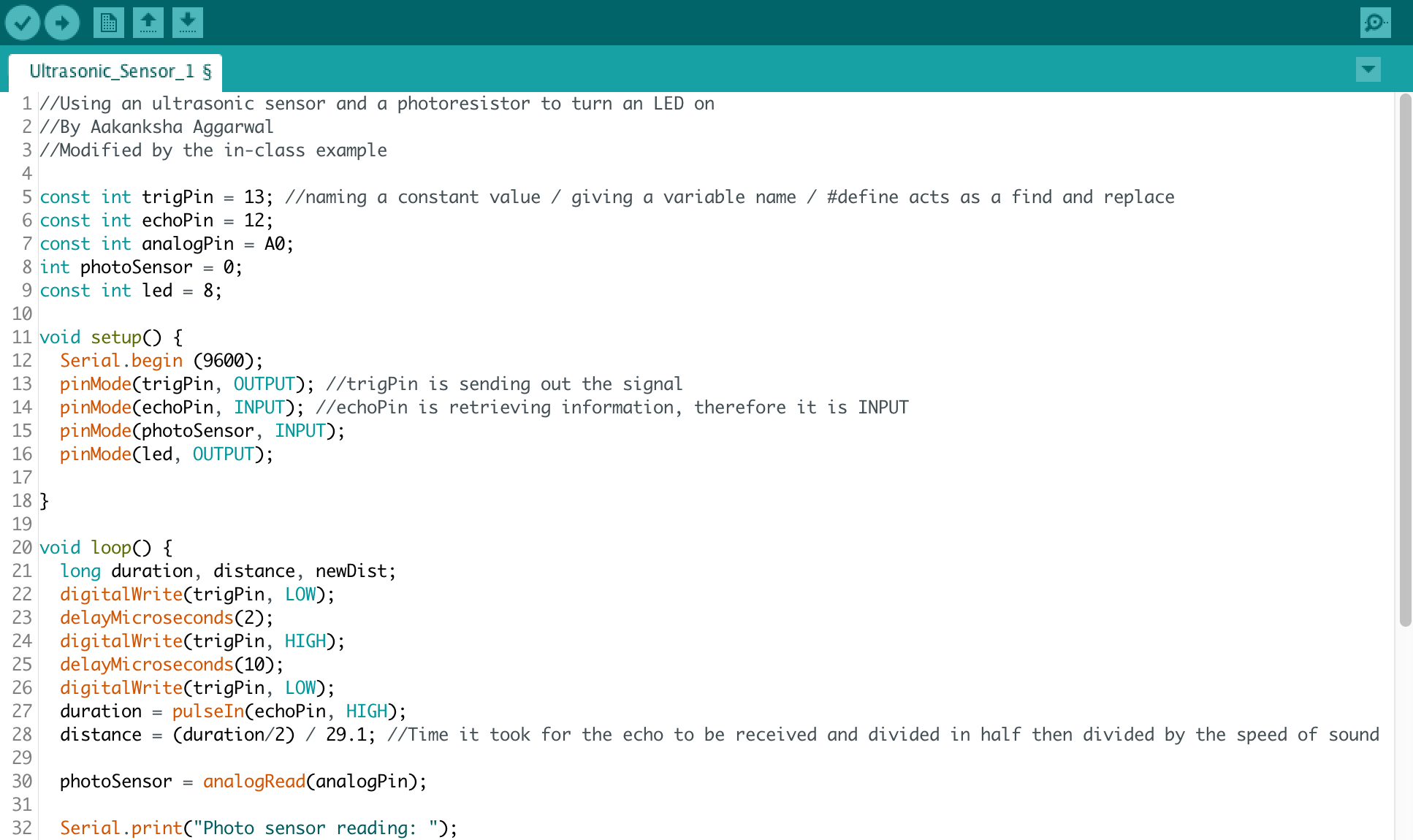
Code