Author Archives: hoe328

Twinkle Stare – Final Presentation Documentation

  • Your presentation
    Online Link:
    https://docs.google.com/presentation/d/1hC8NEC84CYO7_m8aihOJW1nSprMXHYKTWJMagTQmW_o/edit?usp=sharing or
    PDF link:
    Pcomp Twinkle Stare_2
  • Concept + Goals.
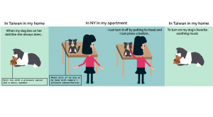
    My concept was to create an IoT device that reconnects me in New York and my dog in Taiwan to be able to feel her presence and recreate a moment we share together. My goal was to be able to feel my dog’s presence over long distance and to spend more time with her somehow. This project is very close to me and I decided to an long distance device because of my dog who is actually sick with cancer back in Taiwan. So I want to build something that will actually work for us.
  • Intended audience.
    This project is mainly for myself so I can spend more time with my dog with her presence over long distance. However, I feel like this device for be for other dog owners who are in long-distance relationship with their dog and would like more presence of their dog.
  • Precedents.
    Pillow Talk is a device that lets you hear the real time heartbeat of your loved one over long distance by Little Riot, which really inspired having the presence sense in my device. SoftBank from Japan also created a series of devices called called Personal Innovation Act, Analog Innovation that helps connect the older generation to the younger generation by translating the new technology we use into older forms such as printing your social media updates in the mailbox as newspapers every morning so your grandma can read updates about you.
  • Description of the project.
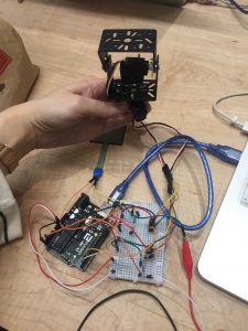
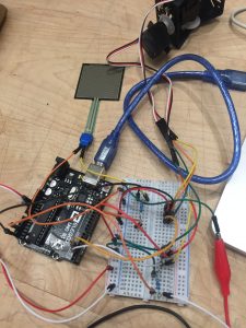
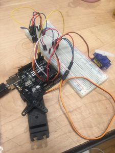
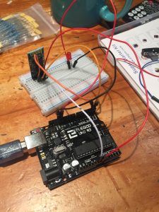
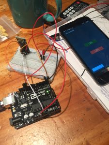
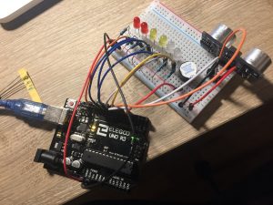
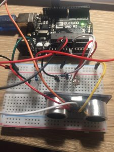
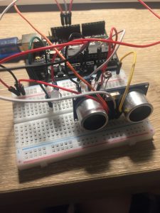
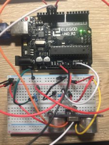
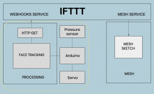
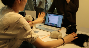
    After confirming my concept, I begin to think about the technical aspects of my project. My device’s interaction has two parts with different interactions. One part will be my dog’s end with her doll embedded with a pressure sensor on which she will lay on it and a speaker. The other part is the model of my dog in my room in New York which will have a face tracking camera, a button, and a pressure sensor built into it. As I began searching online for the details of how to make these interactions work, I was also introduced to two tools that could help with the long distance IoT connection to work. One tool is the MESH sensors which consists of 7 block sensors which each has a built-in function such as tilt, led, button, motion, and more functions to make prototyping and building project easy for the Internet of Things. The other is the IFTTT the free web-based service to create chains of simple conditional statements, called applets, to connect with different applications and services over the internet. Both tools are extremely helpful for my IoT device, however, I want to make all my interactions work properly first offline. First of all, I decided to figure out how to get the face detection to work on camera. I used an Arduino controlling to a servo motor and connecting the servo motor to the OpenCV face detection on a program called Processing to track faces when it moves from left to right on the screen. Thankfully, I spent a few days studying the open source code example online and made face tracking work with no problem. Next was to get the pressure sensor connected to a trigger to open the face tracking camera to start tracking face detected when it is pressed. This was a part where I was stumped and frustrated because I could not get the code to work with my own ability. With some help from my peers, I was able to get the pressure sensors to work to open up the camera to start face tracking when it is pressed and another pressure sensor to turn in off. However, there was another one problem I encountered with my code which was that it can only be run once. If I want to try to press the pressure sensor to turn it on again, the sensor cannot read my pressures values anymore. I would have to rerun both the Arduino and Processing sketch for it to work again. After some debugging, I discovered that it was part of the Arduino code that made the instructions appeared to be stuck in a loop. After modifying my code, my code was working fine, though, at times unstable, I decided that with the time I had, I would not make the IoT connection happen but just focus on the interactions and the physical doll of my device. My whole framework to make this IoT device work is displayed in the diagram below. What I’m focusing on is the interactions on the left. Ideally, I would incorporate this with the MESH sensors and by using the IFTTT webhooks service to send to communicate with my MESH sketch.
  • Video documentation


  • Materials list

    For the face tracking part: 

    Software Required
    Firmware Required
    Hardware Required

    For the physical making of the doll –

    • Fluffy Socks – http://amzn.to/1FwCmTk, http://amzn.to/1NWUkhD
    • Polyester stuffing – http://amzn.to/1Ke62Wy
    • Sewing Kit – Amazon
    • Process + Prototypes.
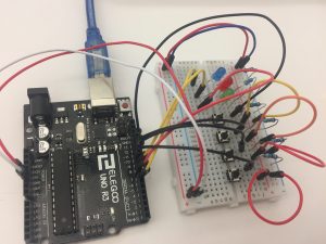
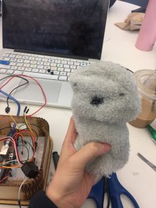
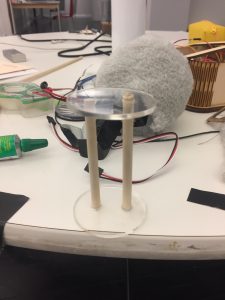
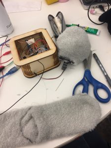
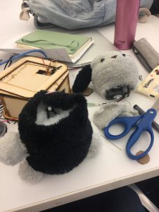
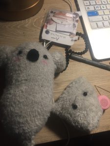
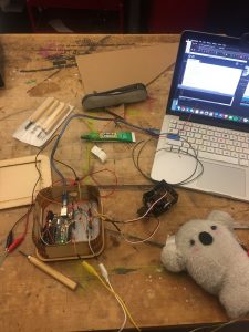
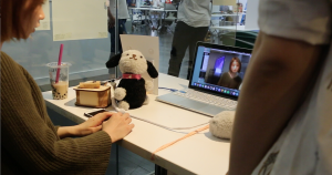
      After making the technical part of my device work, I decided to quickly move on to the physical enclosure. The physical enclosure of my device consists of two parts. One is the doll that my dog will lay on and the other is the model doll that sits in front of my desk. I completely underestimated how hard it is to put anything physical together, even if it is something cute and furry such as a doll. Somehow, the thought of making a doll to me seems simple to me. Not until I started a few tries with making a doll did I realize that I have a lot of practice to do. I thought of taking apart an actual doll but I also wanted my doll to be customizable so I decided to make one myself. To start off, I used fluffy socks as my main material and stuffed it with polyester fiberfill. I made a koala doll as the doll that my dog lays on. This was easier to make as it is such a small doll with no body. Then, I moved on making the model doll of my dog. With my limited experience, it was hard to me to make a model of the dog that looks exactly like my dog. One of my first versions of my doll was unable to stand up properly so I had to make a stand stuck onto an acrylic board and put it inside the doll so the model doll could stand by itself by itself. I then glued the servo onto the board and cover it with polyester fiberfill and put the sock fabric for the model’s head over it to make the model’s head. After getting the body to sit properly on a flat surface, I moved onto making the head. I put a web camera into the head and cut a small hole for the web camera to be able to peak out through the sock fabric. The web camera, however, did not work well hiding inside. One problem is that the web camera is very sensitive to the lighting, the distance, and the height of where you stand. When testing with the web camera inside the head of the doll model, the camera had a hard time detecting face and would jump from different shadows in the screen which causes spasm of quick movements. Another factor that was contributing to this unstable web camera screen was the fur from the sock material I used. This seemed to disrupt the clarity of the screen with a few furs sticking out along the side of the hole I cut. Therefore, I made a hard decision to connect my device to my computer’s camera to ensure the most stable and accurate face tracking. In the end, I was able to put together a functional model doll of my dog. The face tracking camera can be triggered by another doll when you press on it (when my dog lays on it) and you can turn it off by pressing on the model’s head. You can also press a button which is using one of the MESH button sensors that will turn on music which will play in the speaker inside the doll.Prototypes-
           
      Playtesting:

      Challenges:

      • Pressure sensor did not work as will as I thought
      • Complexity of the code
      • Webcam did not work well behind my fabric + distance issues
      • Time Management
      • Aesthetics doll’s with many wires sticking outFuture Iterations:
      • Refinement on the design/look of the doll with no wires with webcam built inside the doll
      • Making it work over local distance and wireless with bluetooth
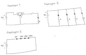
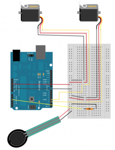
  • Circuit diagram.

Continue reading

Week 12 Documentation – Final

 12nd Iteration of My Prototype

  • Goal of the project and/or desired interaction
    I hope to be able to press on a force pressure sensor to activate the camera for the face detection to track my motion and then turn the camera off by pressing on another force pressure.
  • Quick description of assembly and list of core components
    – Arduino x1
    – Small Bread board x1
    – Force pressure sensors x2
    – Servo motor x2
    – Jumper wires
    – Resistors 220ohm x2
  • How it works
    When you stand in front of the camera, it will not work but when you press on 1st pressure sensor, the camera will start tracking your motion and turn towards wherever you are moving. You can turn the camera off by pressing on the 2nd pressure button.
  • Any problems you encountered and/or solved
    I have encountered many problems with the code where the code tends to be stuck in an IF statement and another problem I still face is that the code only runs once. After running once, it won’t activate again unless I restart the Arduino and processing sketch again. I still haven’t figured out what is the problem since the code looks all correct.
  • Images of your circuit
  • Processing/Arduino Code
    https://github.com/lynnn43/PhysicalComputing/blob/master/SerialServoSketch.ino
    https://github.com/lynnn43/PhysicalComputing/tree/master/LisaPanTiltFace_1


2.  Your playtesting plan and desired feedback

Who will you playtest with?
I will playtest with my fellow peers from Design & Technology program and possibly some other same age peers from different programs in Parsons.

How will you get their consent?
I will ask them if they are willing to test out a quick interaction and give me some feedback.

What feedback do you want?
I want the interaction of my model doll dog to be intuitive so I know where to exactly design my pressure sensor on my model dog.

What questions will you ask?
What is the first intuitive response of placing your hand at (on my model doll dog)?
Where do you think you can press to activate music?

What information do they need to know before starting?
I will give them a basic overview of my concept.

How much will you help them during the test?
Aside from trying to give them a basic overview, I will try to let them figure out themselves. If they really need help, I will give them hints.

How will you debrief them?
I will let them know what I’m really testing orally and ask them if they have any questions.

Continue reading

Week 10 Assignment -Final


Continue reading

Week 7 Wireless Assignment – Lisa Ho

  • Goal of the project and/or desired interaction
    This week our homework was to choose one of the wireless topics covered in class and put it to practice for use in everyday life. I choose Bluetooth because it would be really cool to be able to communicate wireless to turn on a sensor. I decided to use Bluetooth to connect to an android phone to turn on and off an LED.
  • Quick description of assembly and list of core components
    1x Arduino
    1x Medium breadboard.1x Red LED
    1x HC 05/06 Bluetooth Module
    1x Resistors (220 ohms)
    Jump wires
    Andriod Phone

  • How it works
    The connection is simple. Only four connections to be made between Arduino and Bluetooth. After that, just connect your LED to pin 13 on one side and connect it to a 220ohms resistor.

    Arduino Pins                Bluetooth Pins
    RX (Pin 0)     ———>      TX
    TX (Pin 1)      ———>      RX
    5V                  ———>       VCC
    GND              ———>       GND

    After connecting all the wires and led, with the Bluetooth module in place, you then download an APP on the android to connect to the Bluetooth module. Then by using the LED app, you can simply turn on and off a LED with a click on the screen.

  • Any problems you encountered and/or solved
    At first, I cannot connect to the Bluetooth for the longest time. I realized the trick is not to connect the RX and TX of the Arduino pins to the TX and RX Bluetooth pins when you upload the sketch. After uploading the code and then connect these, the Bluetooth will connect fine.
  • Images of your circuit
     
  • Arduino Code
    https://github.com/lynnn43/PhysicalComputing/blob/master/bluetooth_led.ino

Week 6 Assignment – Lisa H.


Part 1

  • The goal of the project and/or desired interaction
    The assignment was to adapt one of the light and/or sound circuits we built in class for another creative purpose. I choose to use the ultrasonic sensor to make an interaction with the buzzer and the LED lights.
  • A quick description of assembly and list of core components— 1x Arduino Uno
    – 1x Breadboard
    – 1x HC-SRO4 Ultrasonic Sensor
    – 1x Buzzer
    – 2x Green LEDs
    – 2x White LEDs
    – 2x Red LEDs
    – 7x 330-ohm Resistors
    – Jumper wires
  • How it works

    When you move away from the ultrasonic sensor, the buzzer and LED lights will not light or make a sound. If you go closer to the ultrasonic sensor, the LED lights will light up and the buzzer will get louder.
  • Any problems you encountered and/or solvedAt first, I wasn’t sure how to exactly get the sound to get louder as I move nearer to the ultrasonic sensor.  But I looked at some code and figured it out.
  • Images of your circuit
  • Arduino Code https://github.com/lynnn43/PhysicalComputing/tree/master/wk5_hwk_sensors

Part 2

  • Give a description of the protocol.

SPI-

It is a synchronous data transfer technique which means there is a dedicated clock signal generated by the bus controller. It supports multi-master bus support and bidirectional transfer. It is a serial data protocol used by microcontrollers for communicating one or more peripheral devices quickly.

There is usually always one main master device controlling many other peripheral devices.

  • MISO (Master In Slave Out) – The Slave line for sending data to the master
  • MOSI (Master Out Slave In) – The Master line for sending data to the peripherals
  • SCK (Serial Clock) – The clock pulses which synchronize data transmission generated by the master
  • and one line specific for every device:
  • SS (Slave Select) – the pin on each device that the master can use to enable and disable specific devices.
  • Draw a diagram or illustration that shows how it works.
  • Give at least 2 examples of when you use this protocol.
    For example, SD cards and wireless transmitter both use SPI to communicate with microcontrollers to communicate without interruptions.

Continue reading

Week 5 – Sensors – Lisa H

  • Goal of the project and/or desired interaction
    This week our homework was to either create a circuit to light up a LED or control a Processing sketch using both a photocell sensor and an ultrasonic sensor. I decided to create a circuit to light up a LED. The criteria include having the LED not light up by itself when the photocell is exposed to light. If the environment is dark but the distance is close, LED will light up. If the distance is far away, the LED won’t light up.
  • Quick description of assembly and list of core components
    1x Arduino1x Medium breadboard.

    1x White LED

    1x Ultrasonic sensor

    1x Photocell

    1x Resistors (220 ohms) – resistor

    1x Resistors (10K ohms) – photocell

    Jump wires

  • How it works
    By itself, the LED will not light up when your hands are not influencing the photocell and the ultrasonic sensor. When your hands cover the photocell which indicates the environment is dark, but your hand is far away, the light will stay off. It’s only when your hand is near and covering the photocell, the light will light up. I used simple if statements with && to make the code part work.
  • Any problems you encountered and/or solved
    I had to write down and think through my if statements and else statements clearly to get it right. At first, I kept on getting mixed up on my clauses.
  • Images of your circuit

  •  Arduino Code
    https://github.com/lynnn43/PhysicalComputing/tree/master/wk5_photocell_ultratronicsensor_hwk5

Continue reading

Week 4 – Lisa’s Lock


Goal of the project and/or desired interaction

This week, our homework was to make a lock that can be unlocked (green light will light up) with a specific pin or password with Arduino. And inserted with the wrong password or pin, a red will light up indicating the password is wrong.

Quick description of assembly and list of core components

1x Arduino board

1x Medium breadboard

1x Green LED

1x Red LED

1x Blue LED

4x Buttons

2x Resistors (220 ohms) for resistors

4x Resistors (10K ohms) for buttons

How it works

There are 4 buttons and 3 LED lights (green, red, and blue). The blue light will be on when the lock is ready. To unlock the lock, the pin is 0, 0, 1, 2, 3. Once you press the right pin, the lock will unlock with a green light that indicates it is unlocked. When you press the wrong pin, the red LED will light up and flashes.

Any problems you encountered and/or solved

I had problems setting up the sequence and had a hard time assigning them to the right buttons. After debugging my circuit and with the explanation and help others, I was able to get the sequence right.

Images of my circuit

Arduino Code

https://github.com/lynnn43/PhysicalComputing/tree/master/pcomp_wk4_hwk_lock


Continue reading