Group member: Xiaoyu, Weilin
Presentation slides link :https://docs.google.com/presentation/d/19OE7jbadUBkxaTjKeHg5-J255E9PJDDEYrXy4R5UUr8/edit?usp=sharing
Concept + Goals.
Autonomous Objects is our Major Studio 2 group project, and we decided to actually build these objects.
Concept:We are making a series of experimental prototypes that explore the ubiquitous but novel relationship between humans and objects. By reimagining the messages behind everyday objects, the project enables everyday objects to communicate and negotiate with us in their (possibly) preferable way.
Intended audience.
This is a project everyone can experience. We want people to rethink their relationship with everyday objects through this fun and playful interaction.
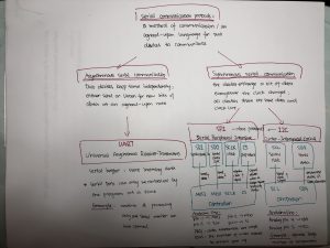
Precedents.
Objects Thinking Too Much @ICC
Description of the project.
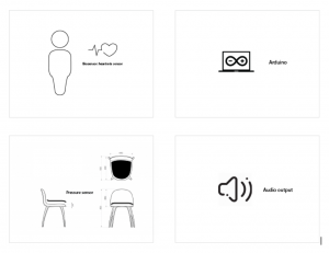
Chair: Chairs also have work hours. They are happy to assist you during work hours but they can also get crappy sometimes. They also preserve the right to refuse anyone when they are on a break.
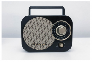
Radio: A radio who lives in the past.
Lamp: A lamp who only wakes up at daytime.
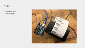
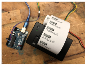
Printer: A printer who needs a break occasionally.
Video documentation.
(Inside presentation link)
Materials list.
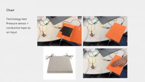
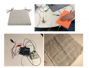
Chair: Velostat Pressure Sensitive Conductive Sheet, copper foil tape, LEDs, alligator clip with pigtail, 9V battery, Arduino battery adapter 9V
Radio: Vintage radio, Adafruit MP3 Shield, Micro SD, SD Card reader, potentiometers, Build-in speaker, Prefboard
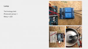
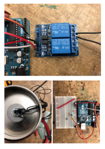
Lamp: Photocell sensor, two-channel relay , light bulb, lamp, 10k resistor
Printer: Mini thermal receipt printer, wires
Process + Prototypes.
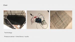
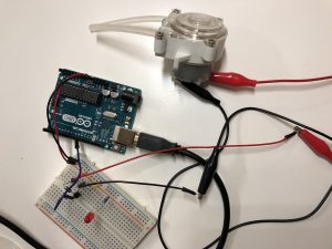
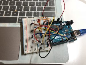
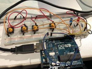
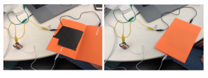
Chair
Sktech:
Prototype:
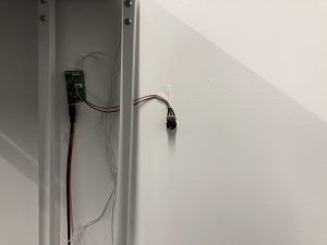
Lamp
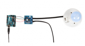
Printer
Radio
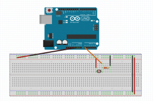
Circuit diagram.
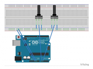
Two potentiometers to A0 and A1.
Speaker directly connect to music shield.
See the tutorial of MP3 Shield
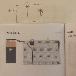
Lamp:
Light bulb part:
Connect the lamp wires to relay: full tutorials can be found here
The Input pin connects to Pin6
If you want to know how light bulbs work, check this.
Photocell sensor part:
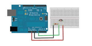
Connect one end of the photocell to 5V, the other end to Analog 0.
Connect one end of a 10K resistor from Analog 0 to ground.
If you want to learn more about photocell sensor, full tutorials can be found here.
Mini Thermal printer:
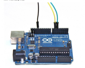
Complete circuit and tutorials can be found here