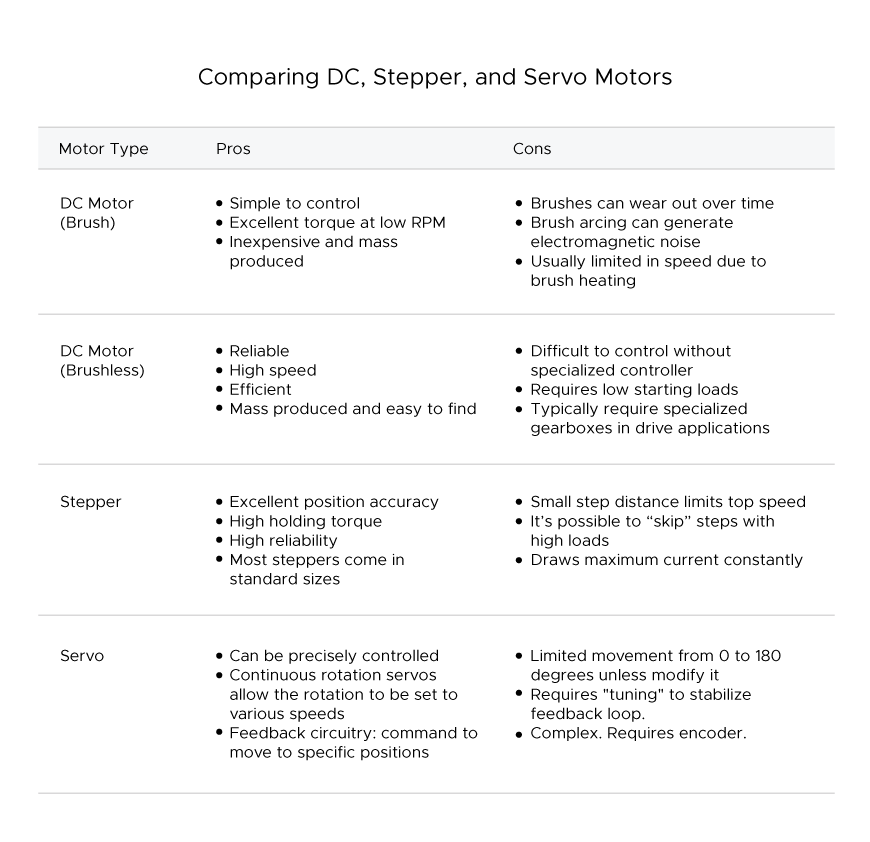
This week is to explore different motors. The first part of the assignment is to shortly describe the differences between DC motors, servo motors, and stepper motors. Basically, the DC motor is the one good for continuous spinning. It runs at a high RPM (revolutions per minute) and can be used for something like fan and blender. Servo motor is easy to connect and can generate high performance. The advantage of the servo is to control the rotation degree from 0-180. Otherwise, if the rotation degree exceeds 180, it will turn counterclockwise. General usage for servos can be robotic arms while its movement is rude along with the noisy sound. Stepper motor is famous for its precise controllability of rotation angles. Unlike servo motor, it can go around 360 degrees with its fractional increments. Stepper motor is good for steady, precise and quite movement such as the mechanism of 3d printing machines.
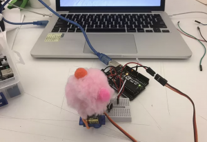
For the self-exploration about motors, I choose DC motor to make a hand blender.
The goal of the project: Using the potentiometer to control the speed of DC motor and make a mini blender.
Components:
1) Arduino
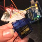
2) D.C. motor
3) NPN transistor TIP120 X1
4) Rectifier Diode X1 (I used 1N4001)
5) 1* 220 ohms resistor
6) 10K Potentiometer
7) Breadboard
8) Jumper wires
How it works:
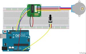
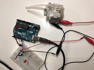
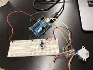
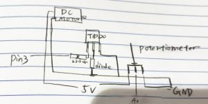
Using the potentiometer( the adjustable resistor ) to change the speed of DC motor, as the value of potentiometer goes up, the motor will rotate faster. Circuit sketch: connect 1N4001 to pin3 and potentiometer to a0.
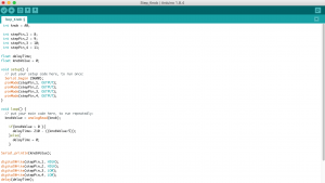
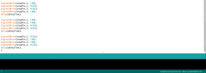
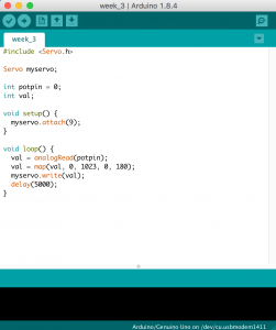
Code:
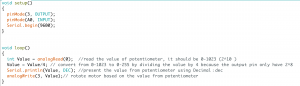
Very simple code, remember to transfer the value of potentiometer from 0-1023 to 0-255 to fit the capability of the output pin. you can use map function but I just roughly divided it by 4.
Problem: the most difficult part is not about the circuit, but the blender itself. Because the rotation speed can be really fast, my handmade blender was thrown out by the motor after 3 sec and I have to tight the blender with iron wire to the motor for several times.