Making things Move: Physical Computing Week 8
- The three most common motors for Arduino include;
- DC motors: Is the simplest of the motors. There are two terminals. When you apply direct current to one terminal and ground the to the other, the motor starts spinning.
- DC motors are usually very fast, often spinning at several thousand revolutions per minute (RPM).
- Will keep spinning until power is taken away
- Depending on electricity the faster or slower it goes.
- Gearhead motors: subset of DC motors that replaces speed for power.
- Examples include computer cooling fans and toy wheels
- Widely used in robotics because of their small size and high energy output.
- DC motors are usually very fast, often spinning at several thousand revolutions per minute (RPM).
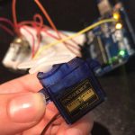
- Servo motors:Servo motors are small in size but very energy efficient and precise.
- Consist of four components:
- DC motor
- A gearing set
- A control circuit
- A position-sensor (usually a potentiometer)
- A servo motor can usually only turn 90° in either direction for a total of 180° movement.
- Servo motor are controlled by sending electrical pulse width modulation (PWM).
- Consist of four components:
- Stepper motors:
- The motor’s position can then be commanded to move and hold at one of these steps without any position sensor for feedback (an open-loop controller), as long as the motor is carefully sized to the application in respect to torque and speed.
- Precise positional control, move 1 step each time
- Slower than DC
- Don’t need to get feedback during the rotation
- DC motors: Is the simplest of the motors. There are two terminals. When you apply direct current to one terminal and ground the to the other, the motor starts spinning.
- To change direction change polarity.
- How do they work: they work on the principle of electromagnetic induction. When you put an electric current through a wire- it generates magnetic field around the wire.
- The blue and red portions are the magnet shields.

Objective: The goal of this project is to better understand how a servo motor can be controlled with a potentiometer through an Arduino. Goal of the project and/or desired interaction
Materials:
-Arduino + USB Cable
-3x M-F jumper cables
-3x M-M jumper cables
-Potentiometer
-Servo Motor
-Breadboard
Assembly:
Servo Motor:
-Connect power wire (red) to the 5V pin on the Arduino
-Connect ground wire (brown) ground pin on the bread board.
-Connect signal pin (orange) to pin 9 on the Arduino.
Potentiometer:
-Plug into breadboard with room for placing cables.
-Outer pins are connected to power (+5V) and ground via directly next to the (+5V) and ground on the bread board.
-Middle pin is connected to analog input 0 on the Arduino.
Download:
-Library Servo.h
-Code Servo Motor Code
Download the library, upload the code, and now you have control over the servo motor.
Thanks to this great Instructables I now better understand the motor components.