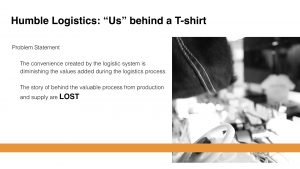
Humble Logistics: “Us” Behind A T-shirt
Concept:
The convenience created by the logistic system is diminishing the values added during the logistics process. The story of behind the valuable process from production and supply are LOST. To target this issue, I am creating a interactive installation, which uses playful and symbolic interactions and metaphoric visual image to trigger people’s compassion and raise the understanding of the human efforts inside the logistics system.
Final Video:
Idea Iteration, Inspiration
1.0 Design Values
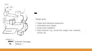
In regard to the outcome and user experience of the piece, I will be delivering following design values:
Theme:
This piece aims inform people with hidden values and human efforts behind sophisticated logistic system because of the rocket development of IoT in e-commerce. This piece will be served as a model for logistics system at a global scale.
Reflection:
The outcome experience shall be playful, informative, and visually memorable. This piece will be using symbolic interactions and metaphoric visual effect to generate compassionate and relatable feelings after players have interacted with the piece.
Perception:
The information within the piece will be presented as a visual symbol of human efforts using fingerprints. The aesthetics of the piece will be aiming at creating a sense of industrial toughness and abstinence to reflect the stereotypes that people had with logistics system but using light mapping to build a warm ambiance around the piece to generate a sense of compassion.
Application:
The target audience of this piece will be e-commerce customers. This piece could serve as an entertainment or advertisement implementation for logistics in theme park or museum.
1.1 Precedents for Inspiration
I believe the best way to tell a logistic story is to use logistics itself. One of the first inspiration was a fieldwork video from Ryan Gander on Vimeo. In this piece, a series of objects and assemblages are placed on a vast concealed conveyor belt. As they pass through an aperture in the gallery wall, the viewer is invited to speculate on the stories they tell, as well as their relationship to one another.
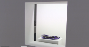

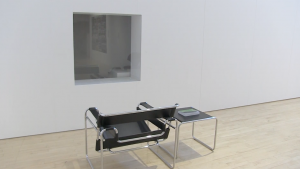
Fig.3 Screenshot from video of RyanGander: Fieldwork on Vimeo, May 3, 2018
This piece provides me with new idea with regard to the use of conveyor belt and transportation device in design. Not only can tangible objects be conveyed but also intangible stories.
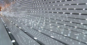
The work, Multiverse, a long, conveyor-belt hall of the National Gallery of Art in D.C, gave me another example of how to create an immersive visual experience with the conveyor belt. This piece used LED mapping on walls and ceiling to create an astonishing visual journey for people riding the walkway.

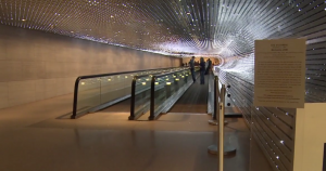 Figure 4 Screenshot from video of Leo Villareal’s Multiverse on Vimeo, May 4, 2018
So, based on these precedents, I become interested in exploring the possibility of using conveyor belt for better storytelling and bring this element and methodology into a design, which also found the base for the design of my installation.
Process: Design upon Research
2.0 Precedents for Execution and Methodology
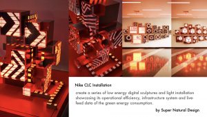
Particularly for this project, I want to use white and black color to bring a sense of industrial toughness and rigidity into the design to align the stereotype and impression that we, as customers, had with logistics system, but the piece should be aesthetically interesting and pleasing. So, for its shape and form, I created my initial draft (Figure 5) based on the work from Nike CLC Installation (Figure 6).
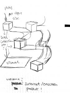
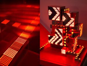
Figure 5 Initial Draft Figure 6 Nike CLC Installation
This example is created by Super Nature Design studio, which uses LED mapping and cargo boxes to create a digital 3D panel for showing work efficiency of Nike company. This piece gave me an inspiration of how I can use lights to set a tone for a work and use simple geometrical shapes to create sophisticated structure.
2.1 Prototypes and Tests
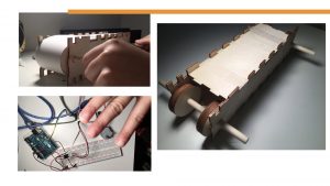
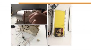
To test out work mechanism of a conveyor belt, I laser cut plywood and paper and build the very first simple prototype, which uses manual force as drivers to rotate the wheels that lead the belt to move.
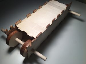
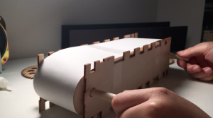
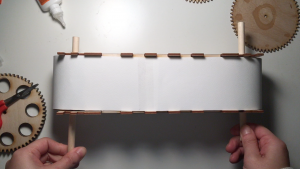
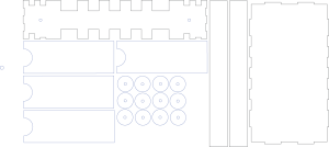
Figure 7 Prototype One – Mechanism feasibility
The success of this prototype allows me to move forward to test out the technological feasibility of this mechanism, for example how much power of a motor or how many motors I need for moving how much weight of an object.
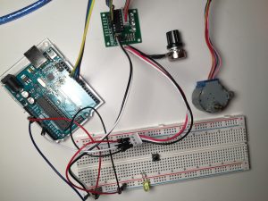
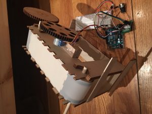
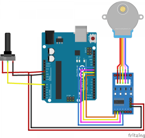
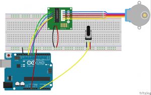
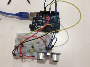
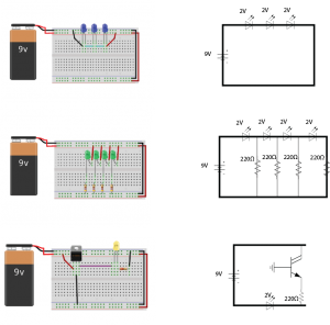
Figure 8 Physical computing
For this particular prototype, I used a 5V stepper motor to test our if one motor is powerful enough to lead the belt moving and also used a potentiometer to test the rate of speed control. Moving forward, I need to calculate the friction and choose the right materials for the belt.
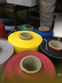
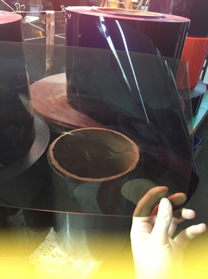
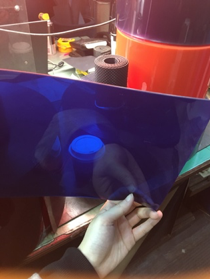
Figure 9 Material Selection
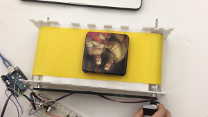
Figure 10 Prototype Three – Components together
After combining each component together, I was able to move a five-pound object (much heavier than a T-shirt) using one 12V stepper motor or DC motor. Next step will be jumping into building the actual installation of the project.
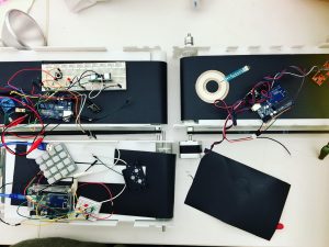
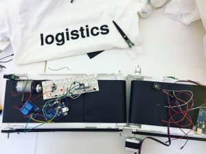
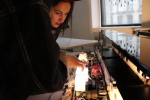
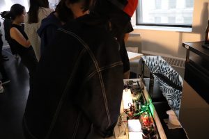
Figure 11 Final Outcome Making in the Progress
2.2 Interactions
According to the article, Selected Activity Coordination Mechanisms in Complex Systems, by Katarzyna Grzybowska, a supply chain, as a sequence of organizations collaborating to provide the largest possible amount of a product or service for the customer, can create very complex interrelation networks at every stage. To simulate this feature of the logistics system, I created three interaction stages, transportation, assembly, and operation.
The decisions are based on considerations of time and scale of the project, and most importantly the processes in logistics system that heavily involve labor forces. To enhance empathetic meanings and endow relatable personal feelings behind those fingerprints appeared in the end, I decided each activity to be finger-based interactions.
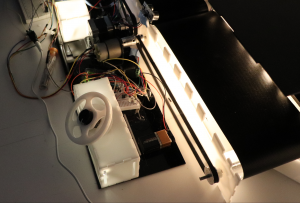
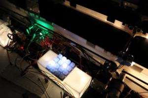
 Figure 12.1 Transportation Figure 12.1 Operation (Trellis) Figure 12.2 Assembly
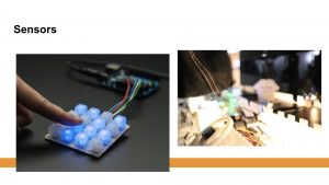
For transportation stage, I used an analog sensor, called potentiometer, and laser cut acrylic sheet to make it look a mini steering wheel (shown in Figure 12.1) that players could use to simulate activities of workers in the transportation session of the logistics system.
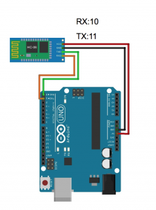
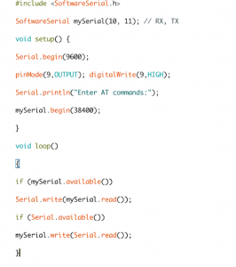
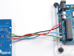
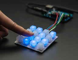
Trellis:
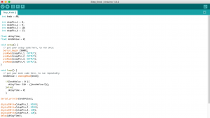
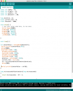
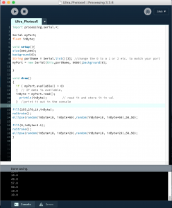
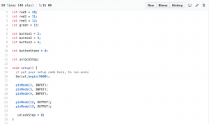
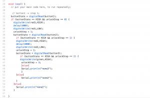
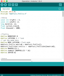
Example code of the logic of Stages (Operation):
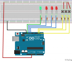
Ultrasonic sensor turns on the stage light and Trellis, doing the right commands on Trellis to lighten up Green LED and make Stepper Motor work.
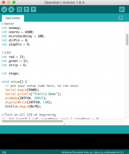
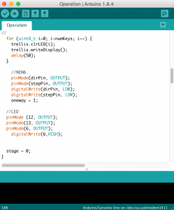
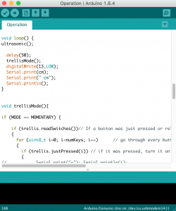

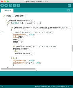
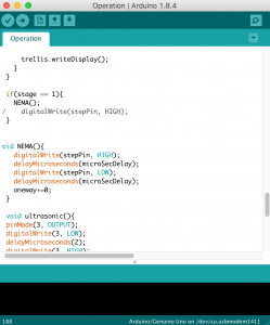
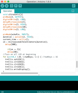
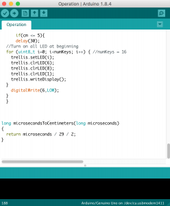
Operation session (Figure 12.2) is the most complicated part of logistics system where lots of activities happen here. Thus, I need to find out which is the most important activity that I want to emphasize based on human involvement. In terms of human involvement, besides manual labor forces, the mental intelligence and decision-making process that people have put into the supply chain management is also a vital part that has been nonchalantly ignored by people. Sending right commands at the right intersection at right time is the key how whole logistics procedures work smoothly together without delay. By considering this significance, I used a mini keypad to simulate the command operation panel in the logistics system, which requires people to push the right command button in the right order once the mini T-shirt is transported to the operation stage.
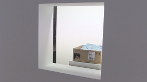
The final interaction stage, Assembly (Figure 12.3), requires players to assemble circuit themselves by pushing two open windows together and make a circuit closed. This is a station where logistics workers assemble everything and prepare to deliver products to their final destinations, which are the front-end customers’ hands.
Github for all stages:
https://github.com/jiany457/PCom/tree/master/Humble%20Logistics
2.3Storytelling and Fingerprints
The idea to use fingerprints to reveal human elements was inspired by the project, Humans of The World, created by designer, Adrien Colombie. He left on a 365-day trip around the world, and, each day of his trip, he interviewed a complete new stranger to reveal their own unique human perspective. By doing so, he also asked them to give him one fingerprint and signature. Every piece comes with the story of the human who carries this fingerprint capturing the essence of their individuality. Using these, the designer created a 365-piece art series called “The Fingerprints”.
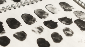
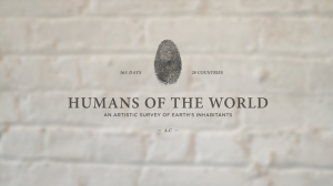
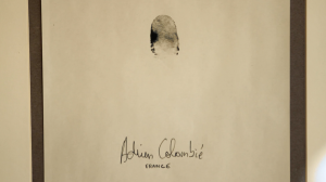 Figure 14 Screenshot from Human of the World on Vimeo, May 6, 2018
For me, fingerprint indicates the uniqueness of individuality, which, I convince, is also a perfect epitome of human efforts. The number of fingerprints shows the number of hands that have touched and handled the object. In addition, fingerprints could be either obscure or clear, light or heavy, which helps to reveal the level of efforts and time spent on each T-Shirt.
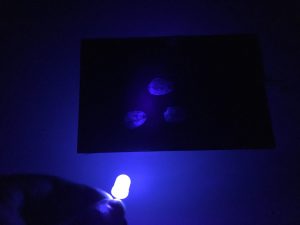
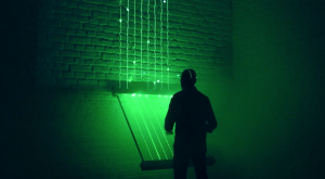
Figure 14 UV Light Test Outcome
To hide fingerprints and make them appear at the time that I want them to appear is the motive that I chose to use UV light and UV ink, instead of regular paints, to map fingerprints on the conveyor belt.
Material:
- LED UV light
- UV ink from Amazon
Reflections from Major Major Exhibition
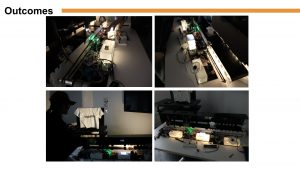
3.0 Final Outcome

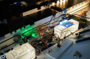
Figure 15 Final Outcome
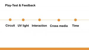
3.1 Player Test and Challenges
Based on feedback from user test, the mapping fingerprints are informatively straightforward, visually powerful, and qualitatively effective in expressing human values and efforts in logistics process. Besides, watching the little objects moving along the conveyor belt based on their interaction is motivational and engaging, which also helps to catch pass-by people’s attention and stop them for a watch. In contrast, some participants responded to me that they wish to have some instructional board or graphs to show the purpose of the interactions in the beginning, as well as provide some context information of the project.


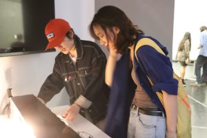
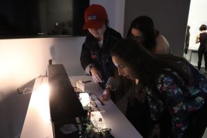
Figure 16 Player Test in the Exhibition
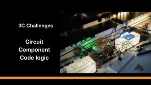
There were two main challenges in the design process, finding the right materials for the best visual outcome and creating an interpretable user interface. In regard to execution, how to organize the circuit in a more aesthetic way also took time. The decision to expose circuit and wires outside is based on the consideration that they are part of the human efforts and process of the logistics system. So, to fully transparentize the story behind the system, wires and infrastructures are also crucial parts.
3.2 Evaluation
Overall, the project was effective at delivering desired content (human efforts) and providing expected user experience (playful and informative). Also, the method for using UV fingerprints as a metaphor for human efforts and values were considered valid. In terms of time management, I did not spend enough time on building user experience and making prototypes for storytelling because of technology prototypes. In terms of exhibition, because the room where the installation at was not dark enough, the final visual outcome was not as clear and conspicuous as expected. Participants were appreciated with the non-abstractness and relatable stories from my idea and my project. In contrast, what was suggested by users for further development were a more comprehensive form and logic interactions and more hybridized mediums. For example, the level of difficulties determines the level of efforts that users have to accomplish, the frequency and the amount of time they have to spend for a better user experience, and a combination of physical interactions on a digital screen to give the project more interactive dimensions.
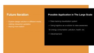
3.3 Future Application
I think, using conveyor belt and invisible UV image are very useful and innovative methods for delivering important messages through design. It provides me with new thinking and ideas that I could develop further into my future projects. The project, Humble Logistics, which works as a model for the logistics system at large, provides a lot of room and space for further application in domains such as marketing, data visualization, environmental protection, energy consumption, etc. For example, if I change the T-shirt to cigarettes or drugs, this project could be turning into an educational one or one for raising health awareness, or advertisement for having a better health condition.
Conclusion
We are living in a world that keeps pushing us to live at an extreme pace, where we get to click to travel, to receive, and to obtain. We seek causes and results, and everything in between becomes minimal and invisible. It is crucial that we, before becoming blinded by the confining world displayed in front of our eyes, we need to step back and give credits and our compassion to those who make all-out efforts to support the world that we are living at. Their stories need to be told.
Based on feedback, the majority of participants acknowledged that they had not thought about this matter until they were informed by this project. They also agreed that this is an important awareness or message that worth spreading. They wish I could push my project further for a more powerful broadcast of the statement.
Final Presentation Slides: