Presentation Link:
https://www.dropbox.com/s/t2ac2prwip2iozi/Objects_%26_Memories_Final_Presentation_051018.pptx?dl=0
Concept and Goals:
Objects and Memories seeks to analyze and project the powerful relations between objects, humans and emotions, and how they connect to evoke memories, nostalgia and rituals, as influential axes for new experiences and associations. Design theorist Donald Norman highlights the importance of the “history of interaction”, the associations and values that people give to objects, and the memories that evoke, over appearance, aesthetics and utility/functionality through the concept of “Emotion rather than reason” (Norman 2005).
The theoretical framework is supported by the development of a lamp inspired by the magical tradition of catching fireflies in a jar, as a playful and gestural ritual that allows users to ‘naturally’ control, illuminate, dim and turn off the light (See image below). This object/experience[1] is also meant to change the bias of relating objects as purely sculptural artifacts, to become elements that fully engage the user, shifting schemes from “observer”, static and contemplative, to “active user” and experience.
[1] Object: Related to certain attributes such as materiality, physicality, form, functionality. Experience: Related to the attributes that are triggered by the human action.
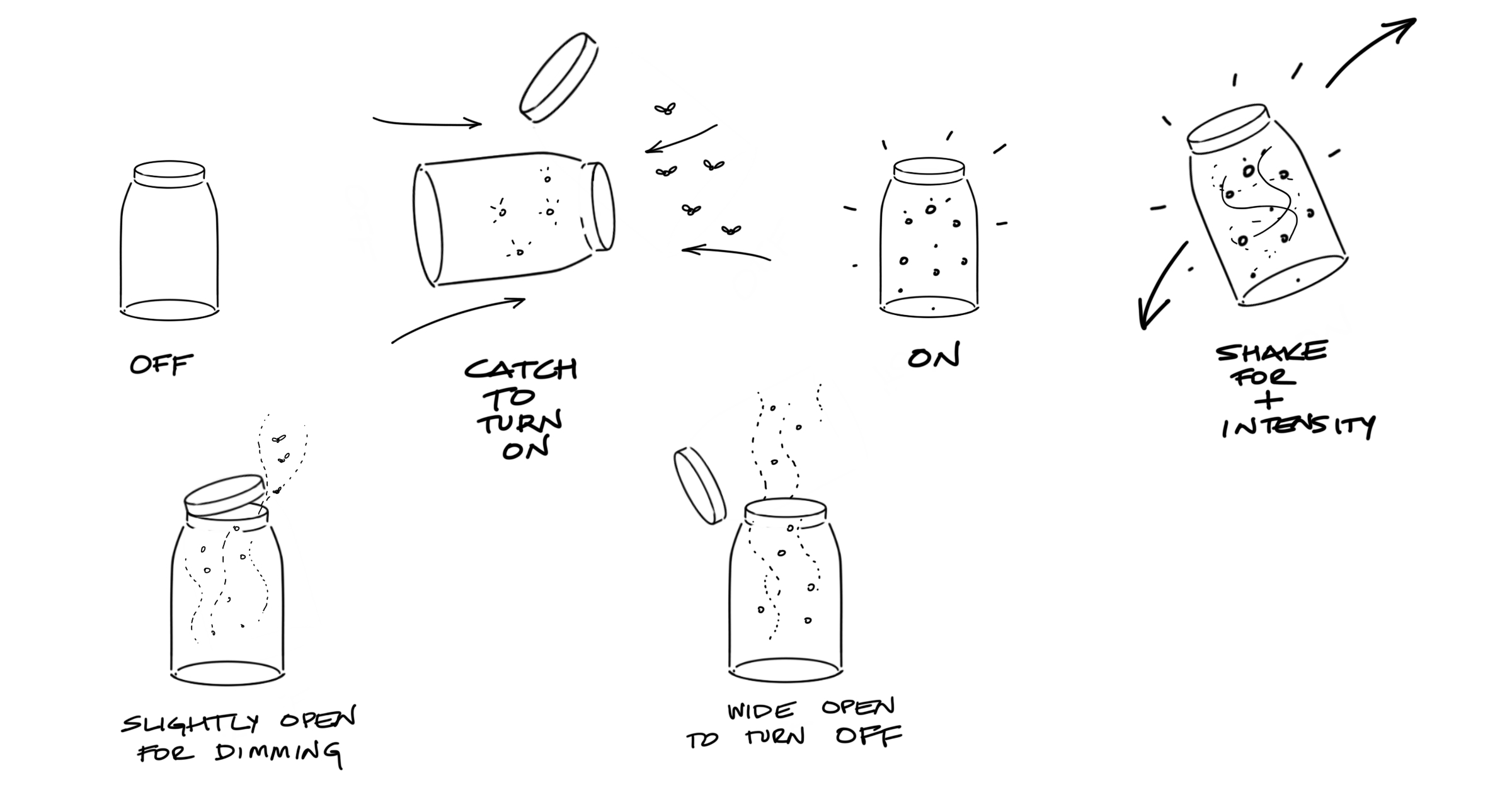
Behavioral process of catching fireflies with the lamp
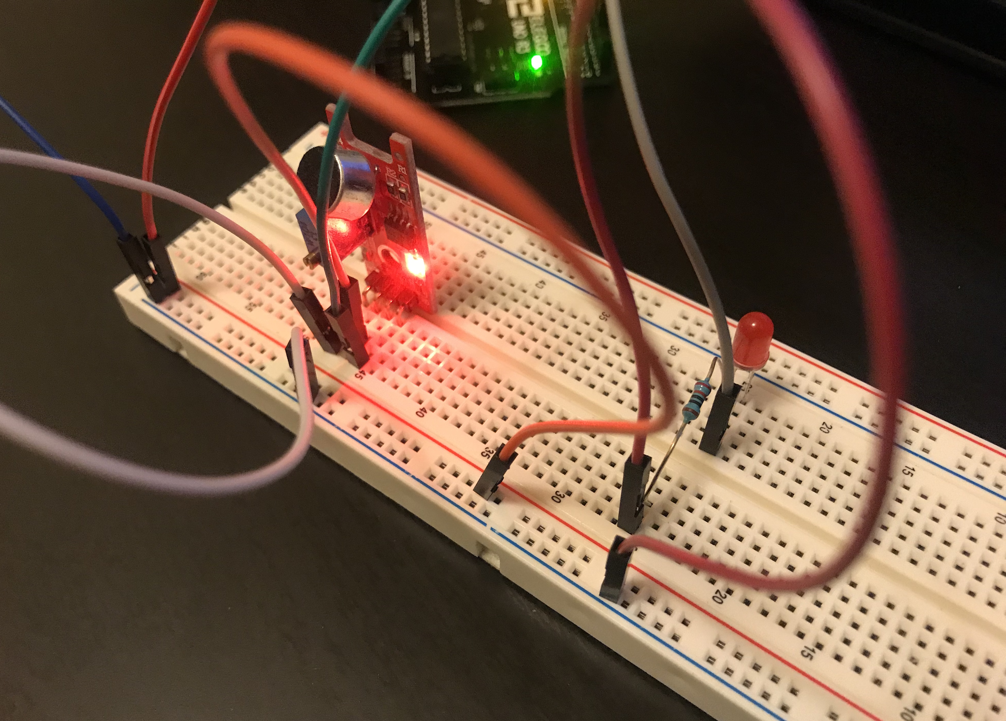
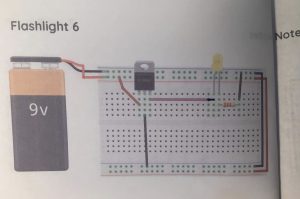
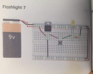
A really valid question was promptly asked at the beginning of the project by my fellow classmates and professors. What is this? Why are you doing this? An important decision taken at the initial phases was to identify the platform and the context in which the idea was to be located. When talking about “flying an LED” (Image): the technical challenge set as my goal, it is easy to imagine the response framed in a sort of installation in a museum, or in another similar context. This is a very interesting path with a lot of potential, no doubt, because these contexts allow the spatial exploration that can configure a completely immersive experience; I totally agree. One of my goals as an Industrial Designer is to change the established paradigms and premises of a purely sculptural profession focused on aesthetical decisions. In addition to create an object that can be accessible and affordable, potentially by millions of people, as I said on the introduction of this document, the ground of this project can be extrapolated to other contexts and audiences…as a unique experience in a museum, as a tool for learning and nature consciousness, as a visualization for a dystopian future where there is limited access to nature and memories. The spectrum for execution and context manifestation is, at the moment of presenting this document, an item open for re-interpretation.
From these principles, the project started with the analysis of the relationship between a potential audience (mostly children from 9 years on, to adults), artifact and experience. The balance of these three elements results in a well-designed object, where the user (observer or operator) represents the axis of the experience, and the ones who have the right answer and insights to be able to argue the decisions on the artifact -Human Centered Design-.
Precedents:
Multiple mood-boards that gave a first formal approach to what it was intended to be shaped as a final product. The original mason jars and the old oil lamps were taken as inspiration. All this was carried out along with an analysis of elements that intuitively transmitted the action of “catch” such as meshes, baseball catcher gloves, nets; these correspond to relevant archetypes to analyzed actions translated into forms (Figure 11). Interesting references such as Infinity Mirror Rooms by Artist Yayoy Kusama, a fascinating way of using mirrors and light to create an immersive experience of endless worlds, and the product “Dreamlights” by Fred and Friends, which showcase a similar experience of using light and movement (like a flying led), and a clever way to hide the mechanisms and LEDs with frosted surfaces.

Mood-boards. Formal Inspiration

Infinity Mirror Rooms by Artist Yayoy Kusama and “Dreamlights” by Fred and Friends
Description of the Project (Process and Interaction):
‘Objects and Memories’ seeks to go beyond the ‘completed’. I’m not presenting a finalized lamp, not even a completed conceptual body; my intention is to keep the boundaries open for future iterations and explorations; this project was meant to be inconclusive…an excited segway to future possibilities.
The Design process model of the that was followed in the course of the project covered 5 phases, which were developed around 3 main axes: 1. The achievement of a design concept that supported the experience and the artifacts, 2. A technical exploration that was based on the premise of how to make an LED fly, and 3. A detailed development of the artifact, which required formal and material exploration, and the realization of 3 dimensions of parts that assembled the object. Each of these phases had several technical, conceptual and human-experience challenges. The intention of the project goes past an academic exercise, but it aims to explore new interventions and experiences, as well as engaging in exciting technical experiments.
It is important to clarify that “User Testing” is a recurrent process throughout this development. The 3 axes named in the previous paragraph were developed concurrently, due to time constraints. Likewise, each phase fed and responded to the others simultaneously, so that progress was made in all the axes.
Process + Prototypes:
Initially, in the research phase, the related boundaries to the experience of catching fireflies were analyzed by describing specific objectives, actions and consequences. The objectives in this phase were raised from the observation of children and adults catching fireflies supported in a ‘playful’ context, and the different ways in which they would catch fireflies. The other important objective was to understand how users would interact with an artifact that has no instructions. In summary, in the process of catching fireflies we can identify 3 different paths. It’s important to annotate that this experience is also cultural and depends in many other factors that go beyond the acting exercise itself. In other cultures, the archetypes used to catch the fireflies range from nets to baskets. All of these icons that are part of the vast objectual domain have repercussions in the effectiveness of the memories, which is highly visual. For this particular creative exercise, I centered the analysis and results by influenced from the western way of catching fireflies.
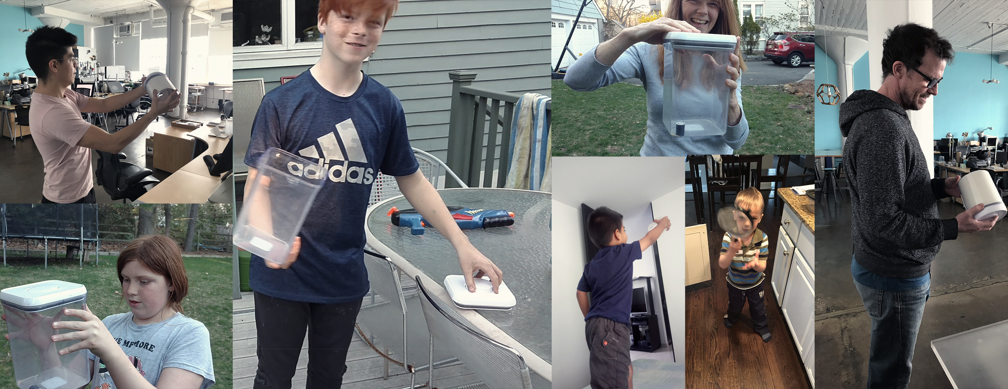
Behavioral User Tests
In this phase, 2D sketches were made and different formal languages were explored that responded to the references of the research phase (mood-boards + inspiration + archetypes). The final result is very similar to the mason jar, since this form invites the experience of catching and containing fireflies, has a base and neutral colors that do not burst with the light that the insects generate, additionally, the lid is simple use and generate direct communication with the product’s operating system. In the same way, 3D developments were created, which aimed to test scale, technical and functional exploration.
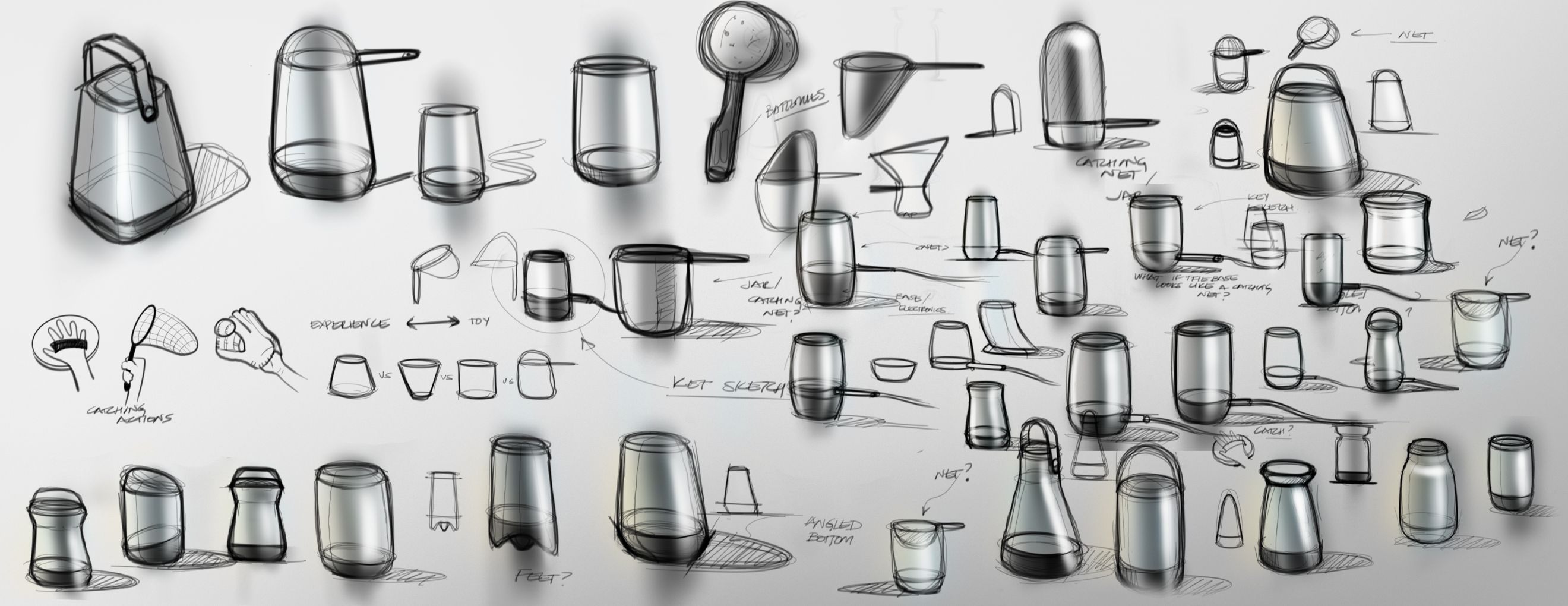
2D Sketches. Formal Exploration
The intention with the first prototype was to quickly visualize the idea and the concept, and to test the interest and reaction of the audience to the overall experience. The prototype is screen based, made from a 120 series of “modified” images where is possible to see the behavior and response of the hardware and experience with the inputs of the user.
First Prototype. Look and Feel. GIF
In this phase was necessary to take approach the project from a technical exploration of considering different ways that resemble the light emitted by a firefly in a mason jar.
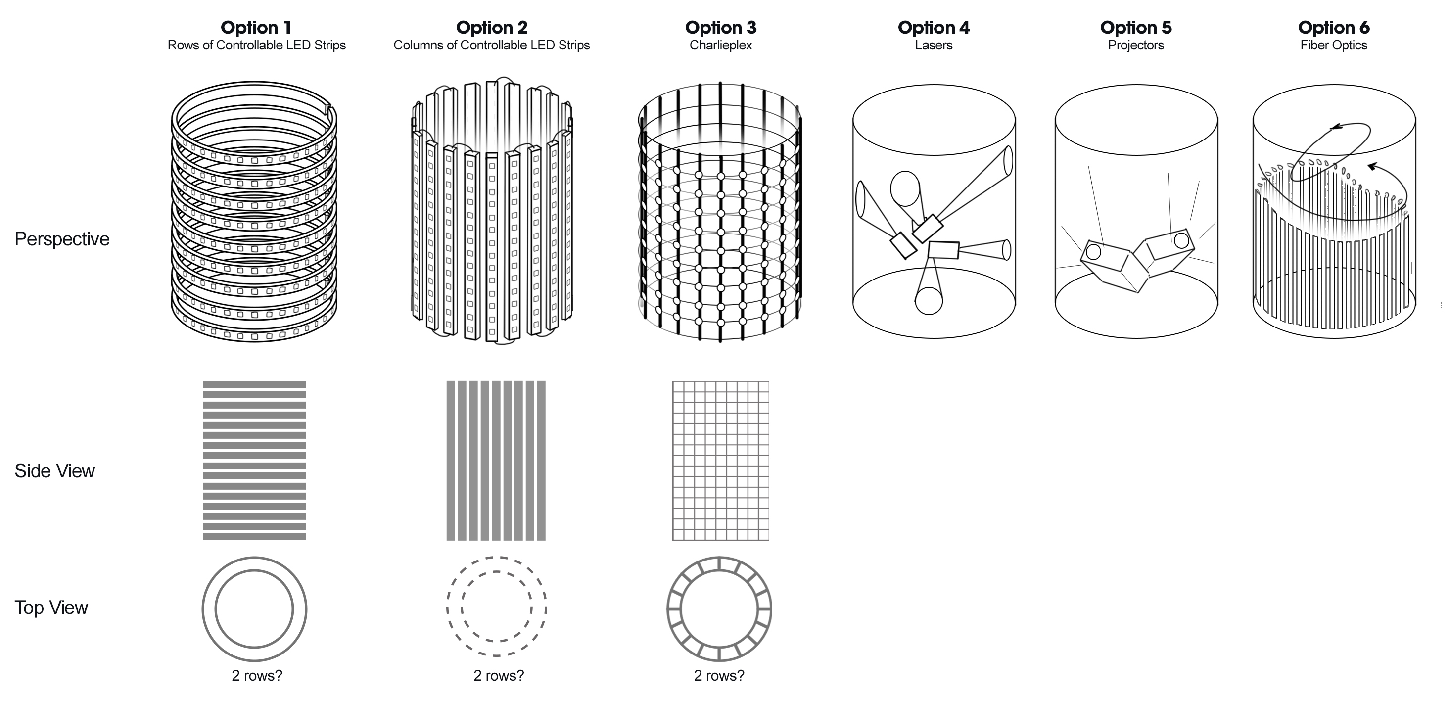
Possible Technical Approaches
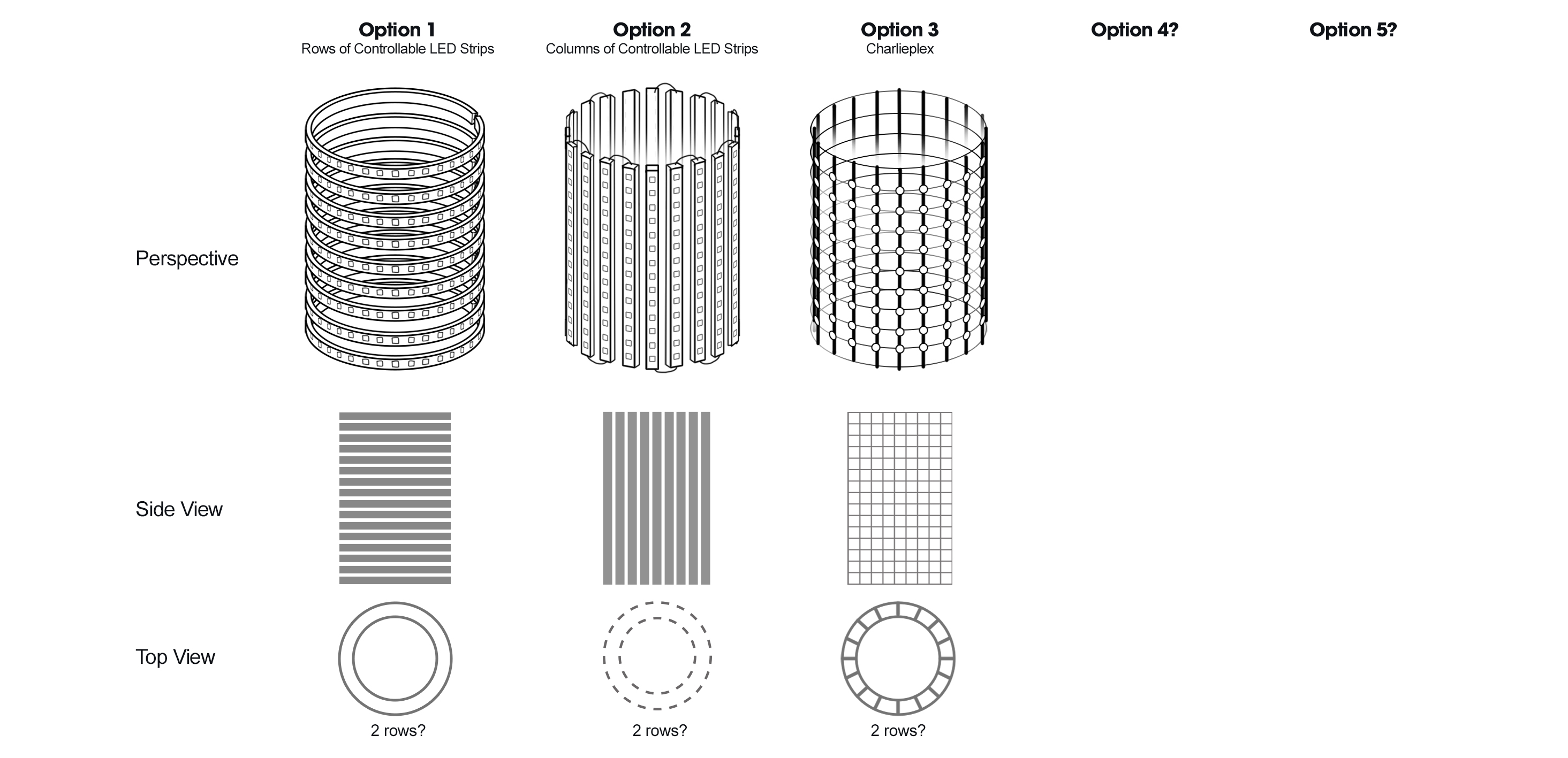
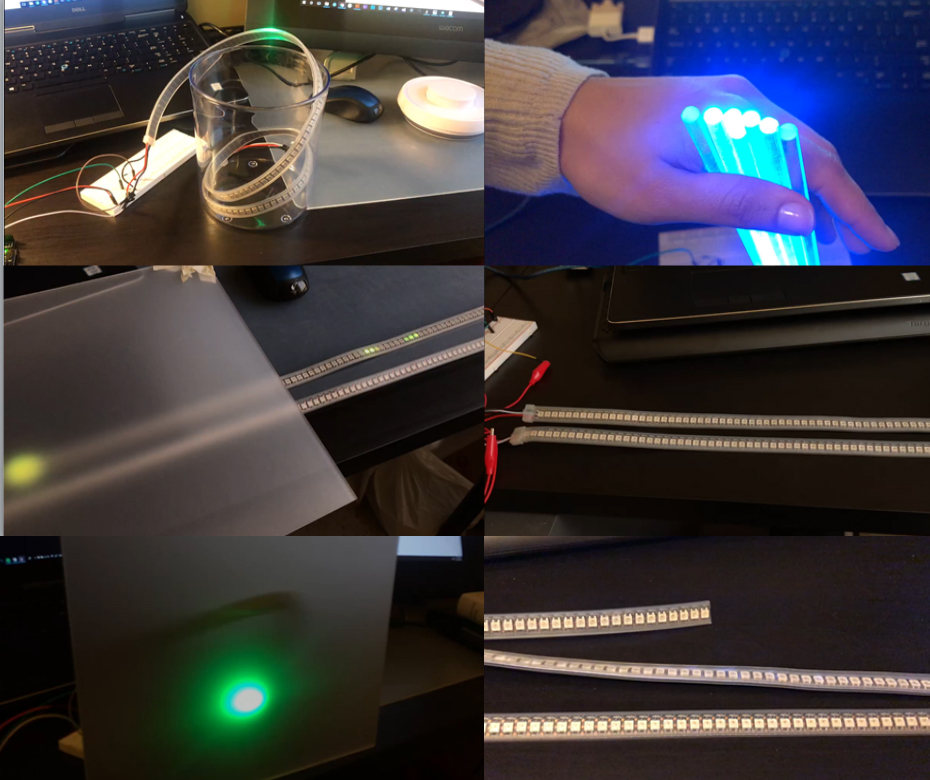
The first technology that was explored was with a matrix of LED’s, which consists in making a cloud of LEDs (soldering one by one) until achieving the desired effect. This matrix was discarded since it requires a lot of space for wiring and hardware (hard-points), besides it is complex to test-build in the desired final object.
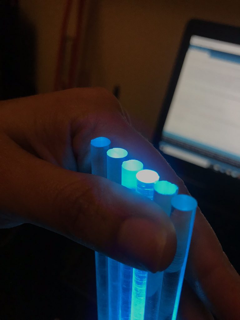
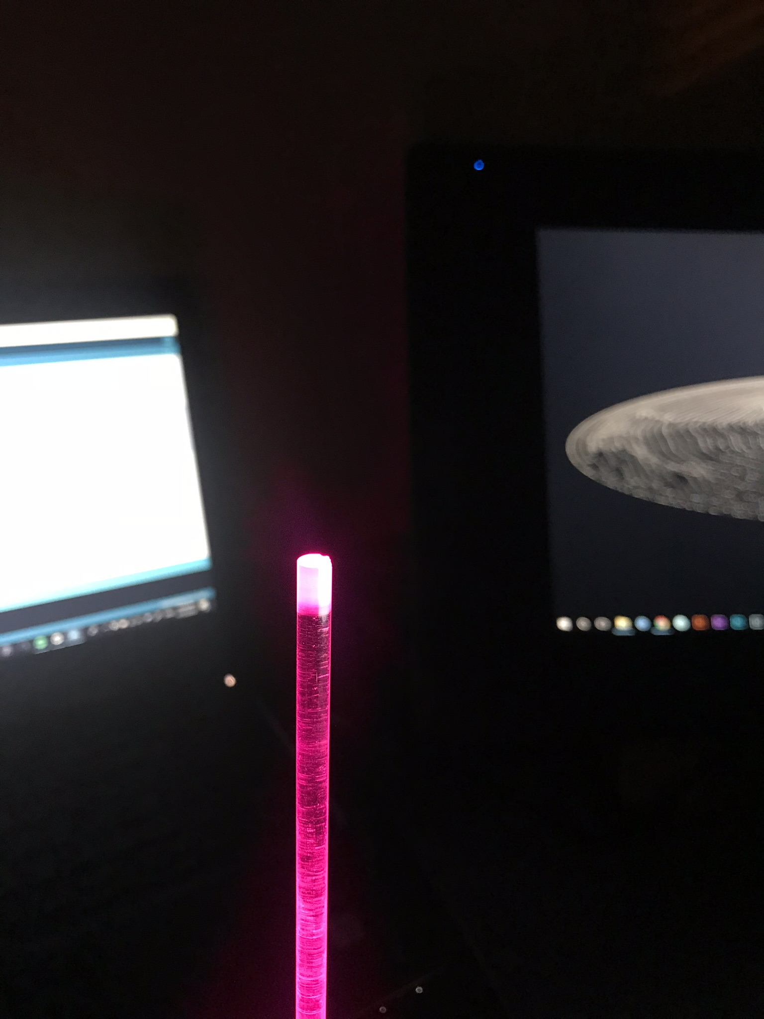
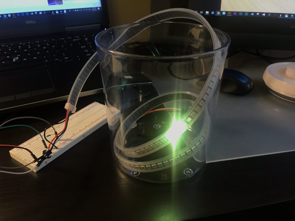
Fiber optic was another technology tested to make the effect of fireflies flying in a jar. This was not a good direction since the intensity of the light was not enough and it also required a matrix of complex LEDs on the base of the object. Lasers, projectors and a mechanical system were other alternatives that were evaluated, but finally the LED’s strip get the desired effect with the variations of speed and tonality of the light. In this option there is an important challenge, since the programmable LEDs drains a lot of current, so a very large battery pack was required, and this must be assembled inside the artifact without breaking its form and optimal operation. Something important to consider is that I wanted to avoid the use of external wires since this may affect negatively the nature and freedom from the traditional activity.
Parallel to this process, the development in 3D plays a very important role to achieve tight scales, tolerances and dimensions that are close to reality and consider hard-points by the selected mechanisms.
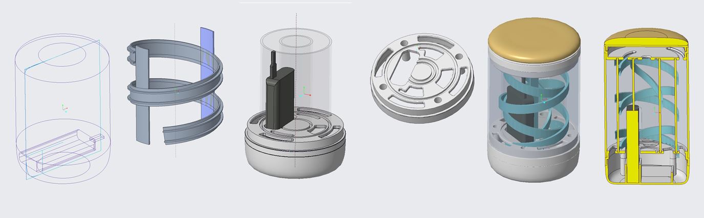
3D Development. Working to package all the components
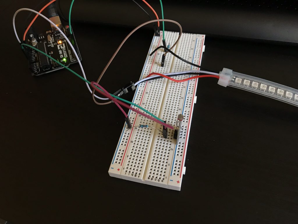
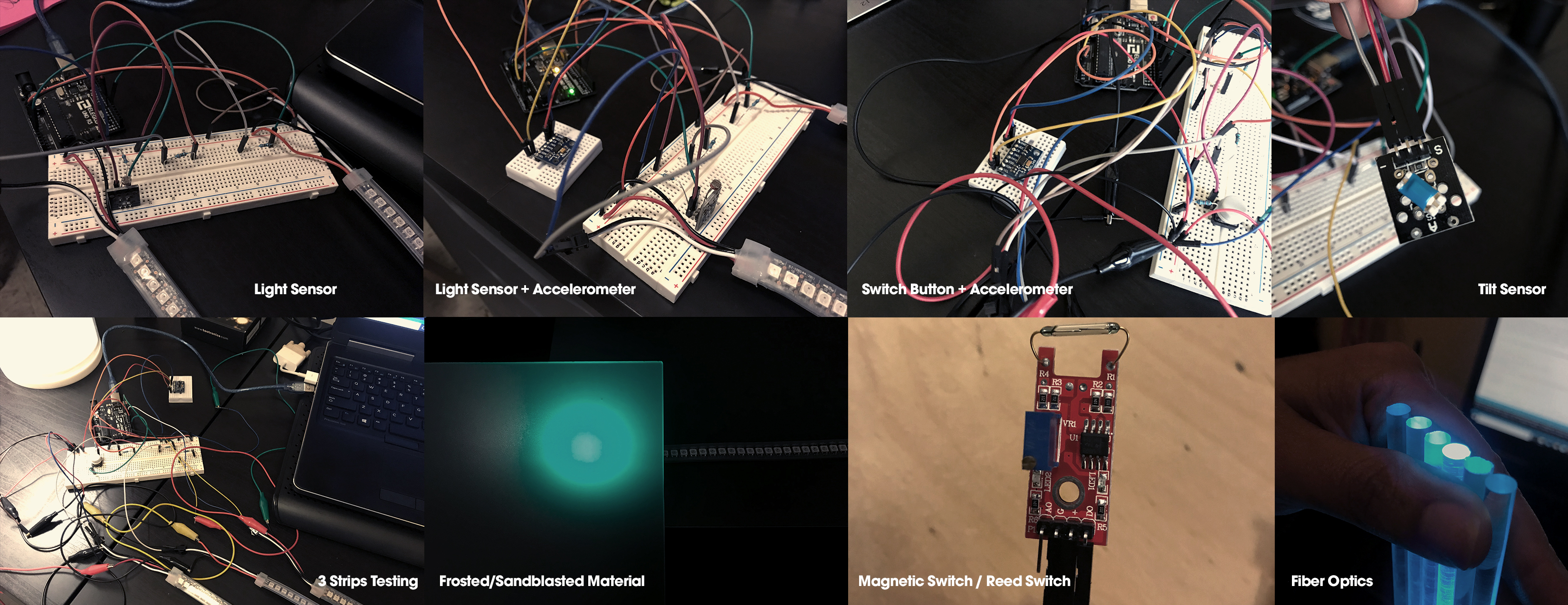
I also tested different effects corresponding to the different behavioral actions from the experience. Each effect entailed different levels of complexity: one Effect with one strip, then one effect with two strips, and finally multiple effects with multiple strips (Figure 17). Also, the alignment between the different sensors and the lights, the response and feedback, corresponded to an important technical challenge. Not to mention problems with the accelerometer reliability, problems with the light sensor, RAM issue due to the control of multiples effects in numerous leds, canvas and brush allocation problems (RAM) from the LED library, were some of the multiple issues and challenges faced during the development process.
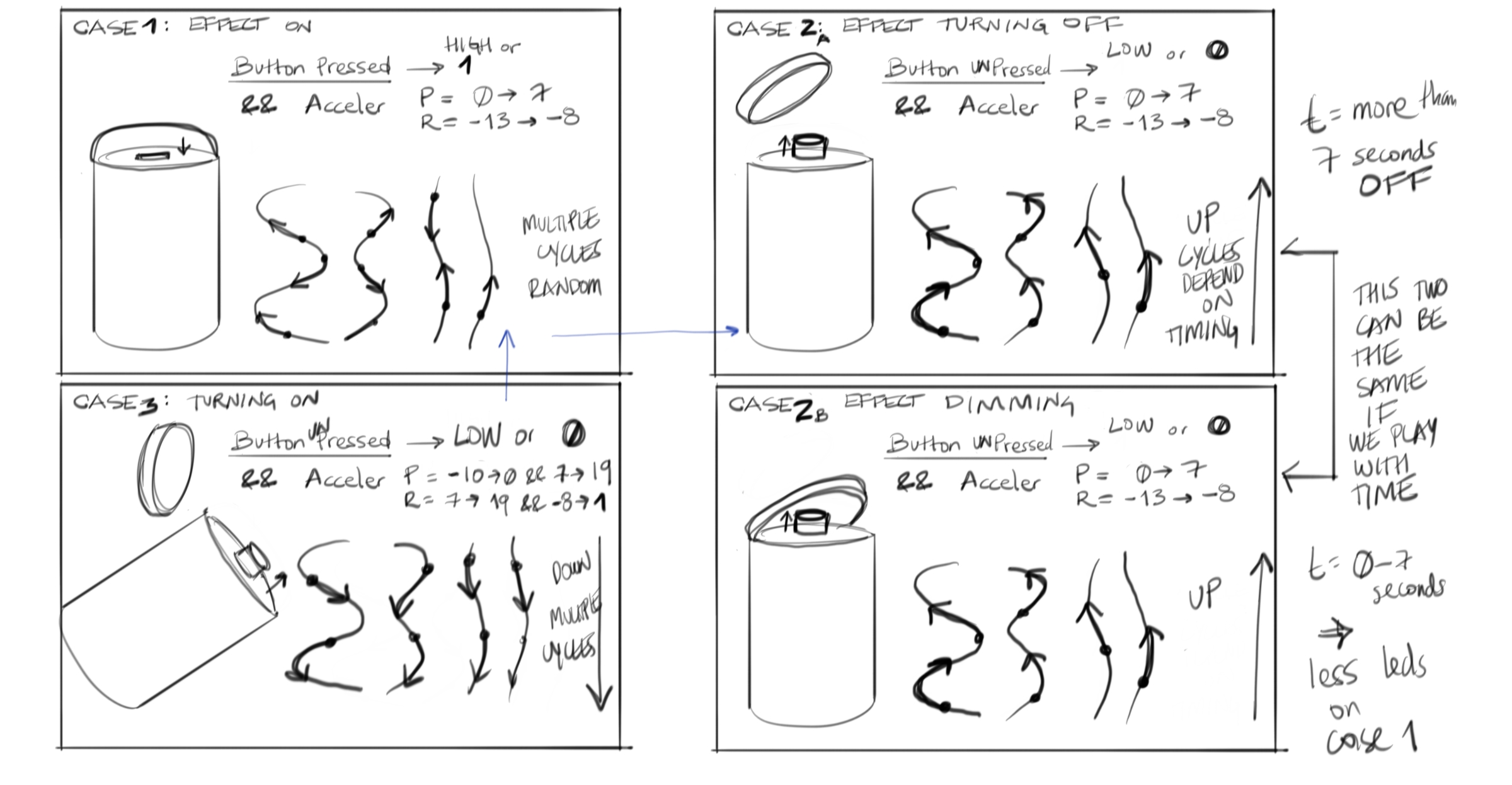
Code Logic Illustration
Construction Process:
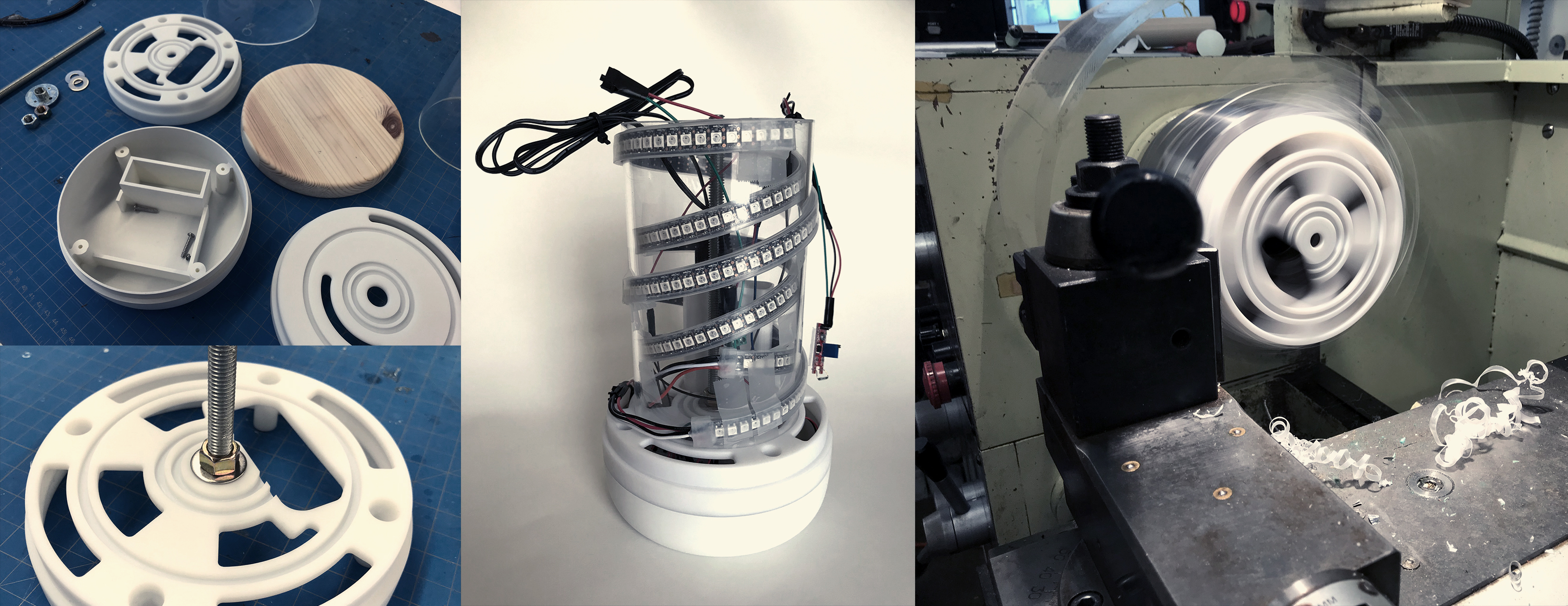
Most of the 3D components I built them in a 3D software and then they were manufactured in CNC.
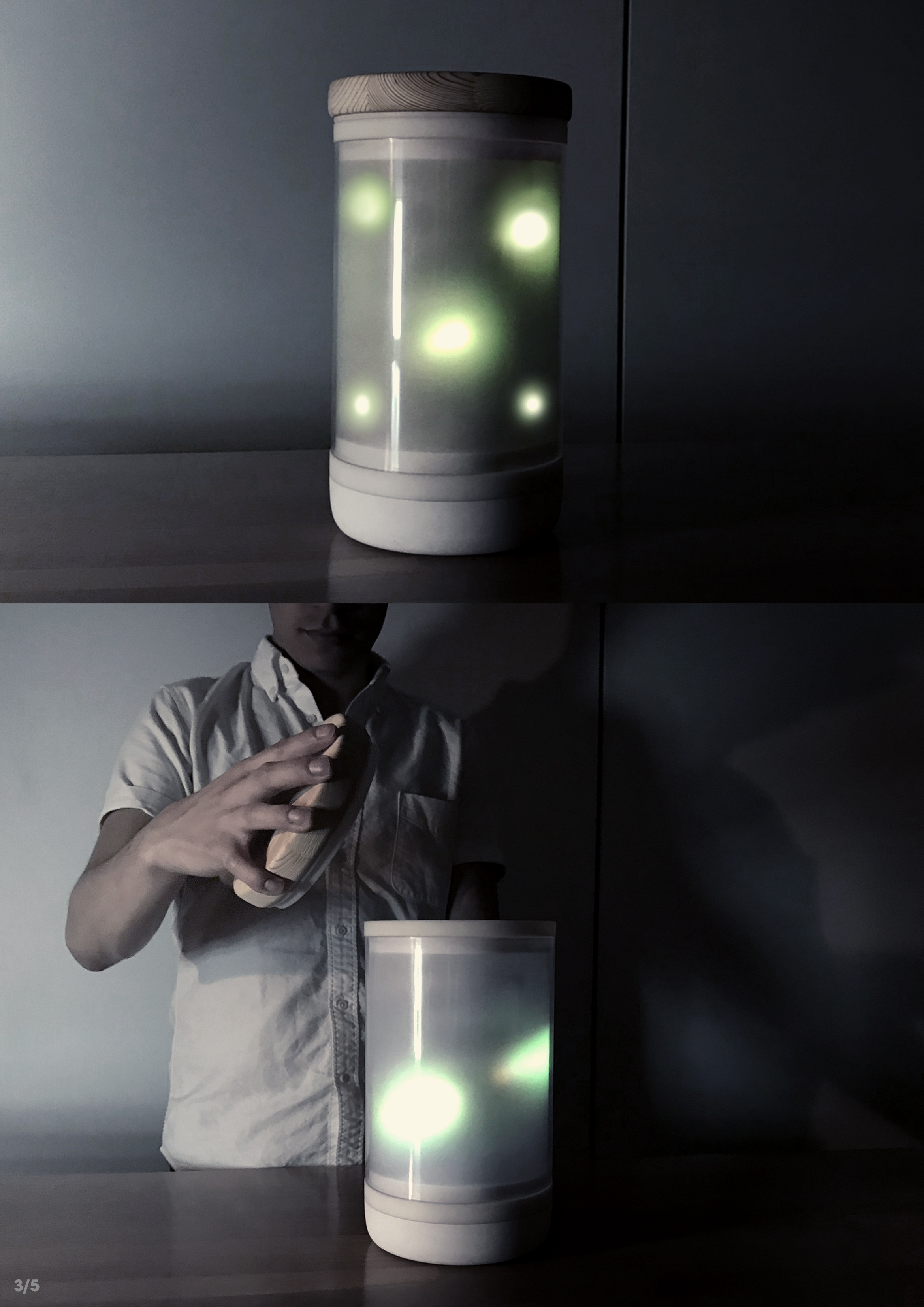
I used 2 clear acrylic tubes, one from the outside and one from the inside where I wrapped the LED strips. I sandblasted the outside tube to hide the internal components.
I shaped the lid from a wooden block in the lathe. The lid has some magnets to activate the reed switch and to close tightly the cap to the body.

Materials:
For the Electronics:
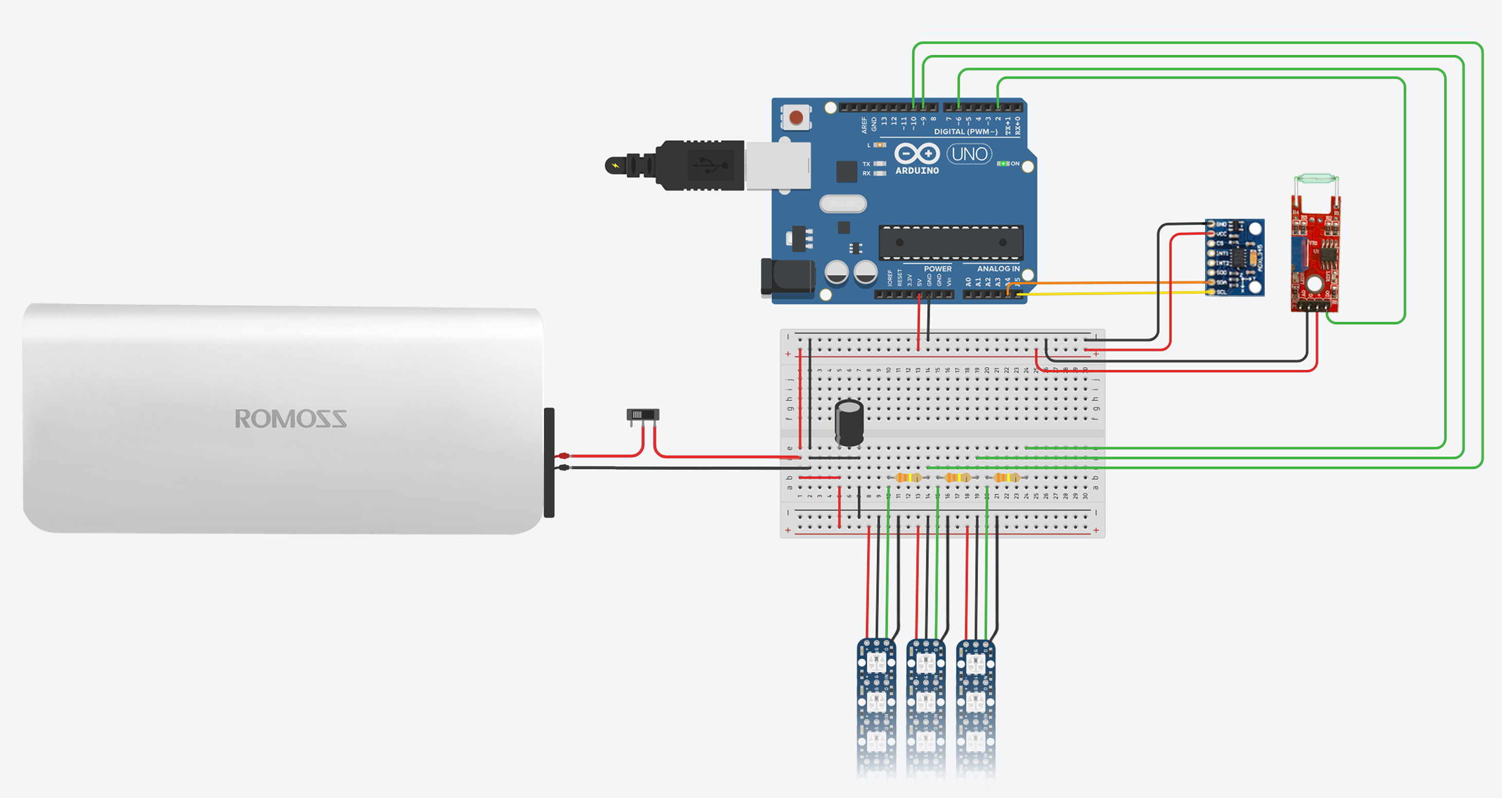
- x1 Arduino Uno
- x1 Breadboard
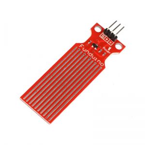
- x1 ADXL 345 Accelerometer
- x1 Reed Switch or Magnetic Switch
- x3 Neopixels RGB strips
- x3 330 kohm Resistors for the Strips
- x1 1000 µF, 6.3V or higher Capacitor
- x1 Battery Pack. 5V 2A
- Jumper Wires
For the Jar:
- Wood block of 2in x 6in x 6in for the lid
- 2 clear cast acrylic tubes. One of 6″OD and one of 4″OD. for the exterior and to wrap the led strips
- ABS. Most of the 3D components I sent them to be machined in CNC
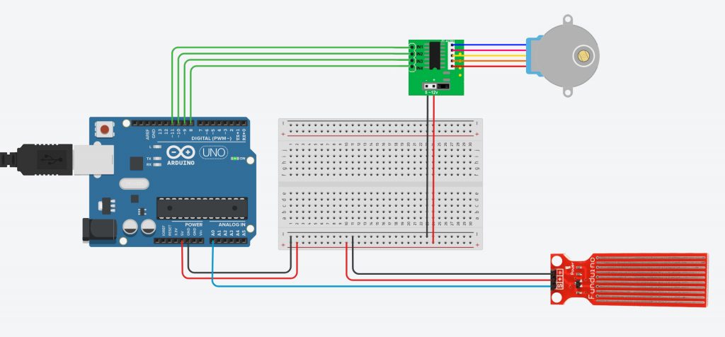
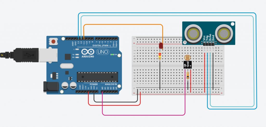
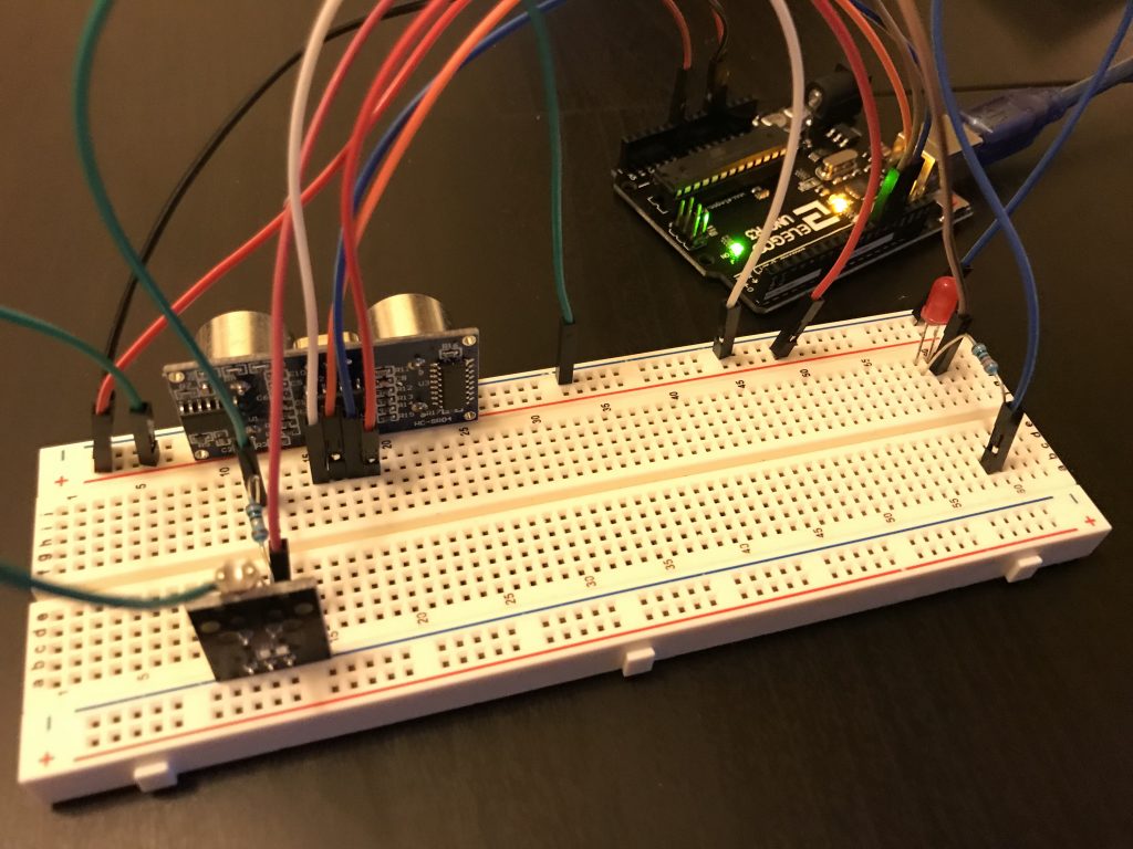
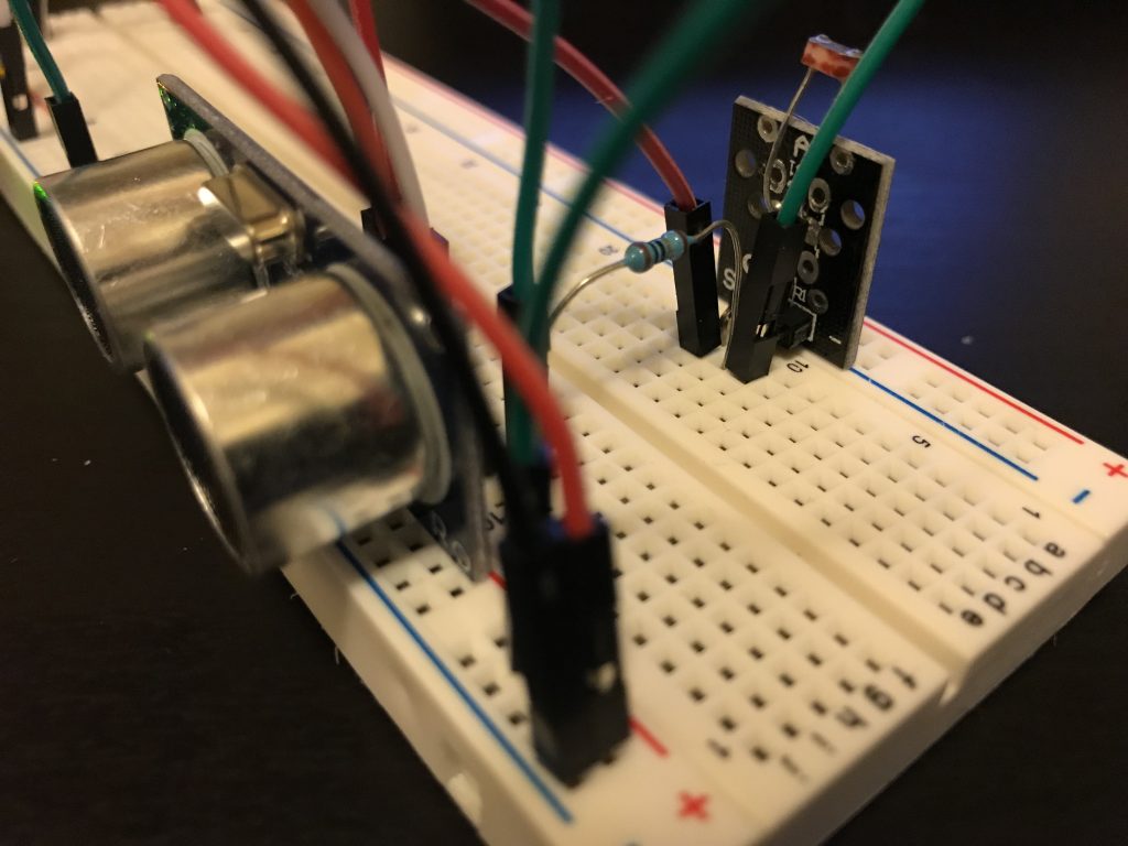
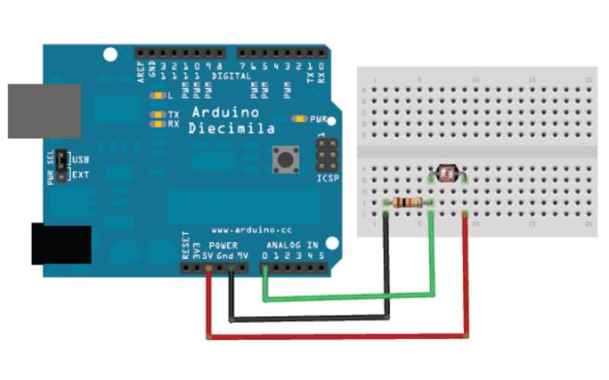
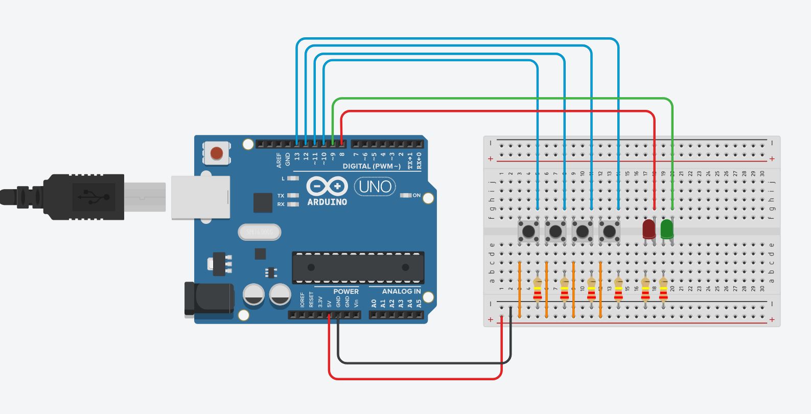
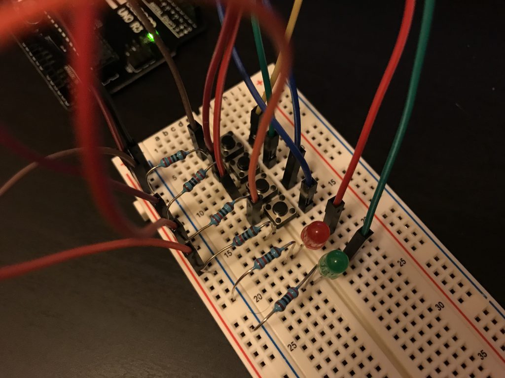
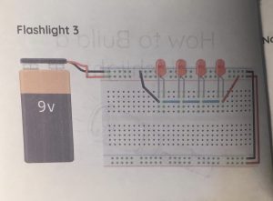
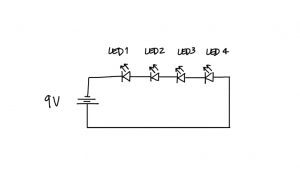
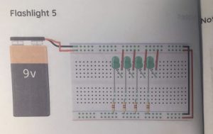
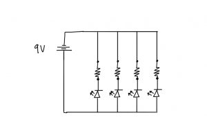
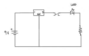
Circuit Diagram: