Category Archives: Week 4 Assignment

WEEK4-combination lock

Description of the project:

The goal of this assignment is to build your own combination locker with led and buttons. For me, I want a combination locker which can use keypad numbers as input and can be controlled by my cell phone. So I choose to use 1Sheeld module and it’s application to build my own combination locker.

List of components:

  • 1sheeld– a wireless shield which can easily attach to Arduino, with the customized application, you can use your cell phone to control Arduino.
  • Arduino Uno x1
  • Breadboardx1
  • 200-ohm resistor x1
  • Red led x1
  • jumper wires

How it works:

first of all, attach the 1sheeld to Arduino, and then connect LEDs to the pin assigned. After uploading the code to Arduino and 1sheeld. You can open up Bluetooth to search 1sheeld and connect to it. Then open the keypad shield in the 1sheeld application, enter the password you set to open the lock. In this project, I used red led to indicate “the locker is not opened”, and it was set it to be lighted up as default. When the user enters the right password, the red light should be turned off.

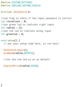
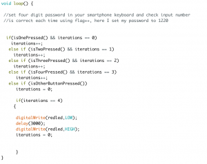
In the code part, using flag function (in here I put “iterations” to represent it ) to set your password. I set the password to “1220”, and every time you press the right keypad the flag will plus one. After fulfilling the 4 iterations (0~3), the red led should turn off.

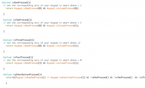
Because of the flag function, the four-digit password should be checked each time, the wrong input such as “4593”, “2340” will not let the red light go off. See the following code for the details:

Any problems you encountered and/or solved:

My original intention is to use two different led lights, a red one for wrong and a green one for right. But no matter how hard I tried, 1 sheeld seems to not able control two LEDs at all. What I tried to debug including change all the components including the breadboard, LEDs, wires, and different pin. In the end, I only use one led to represent the lock status.


Week 4

a combination lock

Understanding the basic logic behind the digital combination lock was the main goal of this project. although it seemed hardcore tech for me at first, thinking it step by step made me realize how simple it is.

Using basic components like Led, 220 ohms resistors, buttons and 10K ohms resistors,  breadboard, Arduino board, jumper wires. you can build your very own safe.

although I realized it required very basic logic, for some reason the lock could work once and stop responding after that, so I wouldn’t recommend putting your governmental papers in such a safe  🙂 so after failing hard I had to use a code from Alyssa: http://lizastark.com/physcomp/alyssas-combination-lock-week-4/ https://drive.google.com/file/d/1OlpTO_oNPYWVEbz0SmbbegJo1Oo0Lawy/view

here is some documentation starting with the failed trial and then after using Alyssa’s code:

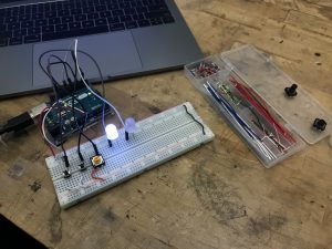
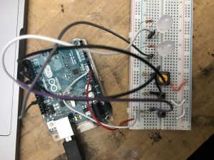
failed

succeed

Thanks Alyssa!

Week 4: Update & Redo

Hello, after my initial two failures I’m back at it again with a copied code. This code is from my classmate Alyssa http://lizastark.com/physcomp/alyssas-combination-lock-week-4/ https://drive.google.com/file/d/1OlpTO_oNPYWVEbz0SmbbegJo1Oo0Lawy/view

My breadboard set up is still functional, though to match with Alyssa’s code I got rid of a button. Here are some videos of my experience:

In this video I am inputting the combination and finding that after the combination is inputted there is no way to get the Arduino to lock/ reset again.

Here I found that prior to putting in the correct combination, the buttons will reset themselves after 3 pushes.


Thank you.

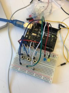
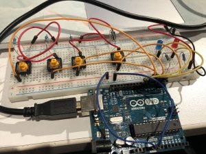
  1. Goal of the project : By clicking four buttons in a certain sequence, the lock will be locked or unlocked indicating by two leds. If it is unlocked, the blue led will light up; if it is locked, the red led will light up.
  2.  Core components : 4 buttons, 4 x 10K ohms resistors, red and blue leds, 2 x 220 ohms resistors, breadboard, arduino board, jumper wires
  3. How it works : If you press buttons from 1 to 4, the blue led will light up and fade out in a while. Otherwise the red led will light up.
  4. Problems encountered : the button is unstable sometimes.

IMG_0696

Alyssa’s Combination Lock (Week 4)

Goal: Build a combination lock using 2-4 buttons, at least 4 button presses, and LEDs indicating locked vs unlocked status.

Components: jumper wires, 3 buttons, 5 resistors (220 Ohms x 2, 10K Ohms x3), 2 LEDs (different colors), breadboard, arduino

Setup: 3 buttons and 2 LEDs with resistors wired to arduino. When the right combination of buttons is pressed, unlock and shine the green LED. Otherwise, lock and shine the red LED.

How it works:

Starts in a locked status, indicated by red LED.

Enter the following combination of buttons to unlock:
Button 1: 2 presses
Button 2: 1 press
Button 3: 2 presses

This combination unlocks, indicated by green LED.

To lock: press each button once. This triggers each button count to exceed the maximum limitation and thus reset to 0.

Continue reading

Week 4 Combination Lock

Goal:

I want to create a combination that allows me to push desired button in the desired order to unlock a green LED.

Description:

3 buttons to control red and green button. Red button means still lock but more step needed, Green button means unlock.

  • How it works: You have to push the 1st button to trigger the 2nd button, then push the second button to unlock the green LED. (Like a step-by-step unlock process)

Problem (solved):

The problem is that I cannot release buttons. Once I push the first one I have to hold it to while pushing the second one to make it work. My original intention is once I push the button even I release it the button will still work.

Materials:

  1. Arduino UNO R3 x 1
  2. Breadboard x 1
  3. Buttons x 3
  4. Red LED x 3
  5. Green LED x 1
  6. 220Ω Resistors x 3
  7. Wires

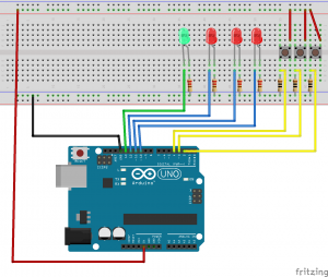
Connection Diagram:

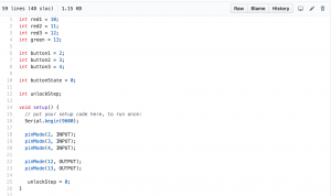
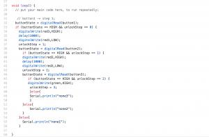
Code:

Github Link: https://github.com/jiany457/PCom/blob/master/CombinationLock/version1/version1.ino


Combination Lock – Dario N (Week 4)

Goal of the Project:

The intention with this project was to learn about the capabilities of Arduino and how this platform connects to analog mediums. In this particular case, the proposal was to unlock a green LED by pressing 4 buttons with a programmed sequence. If the sequence is not pressed in the correct order, the red LED will turn on or the system is still locked.

List of Components:

  • x1 Arduino Uno
  • x1 Breadboard
  • x4 Pushbuttons
  • x6 220 kohm Resistors
  • x1 RED LED
  • x1 GREEN LED

Assembly Process:

The circuit is made of from 4 Buttons and 2 LEDs. All the components are connected in series with 220kohm resistors (in the case of the buttons, they help the charge to drain away when the button is released, for the LED, they help to limit the current flow to a safe level to the LED). Each button (INPUT) component is connected to the digital pins, and the LED (output).

How it works:

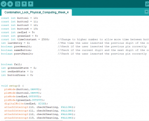
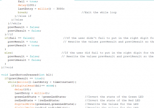
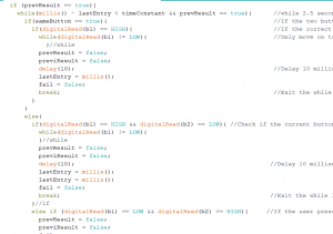
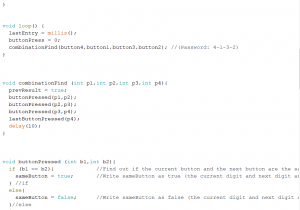
The Arduino program is constantly reading if a button is pressed and it’s telling it the sequence is correct or not. if it’s correct (true) and the previous button pressed is correct (true), then the green LED will light up; if not, until the buttonlenght (number of presses-4) is true, then the Red will turn on.

Problems:

This program is based on a program I found on internet (https://www.youtube.com/watch?v=7HeT4wvgz7w). The challenge consisted in getting to understand the code (I’m fairly new at coding), and to modify it to be more understandable and to function with the required components we had in the brief.

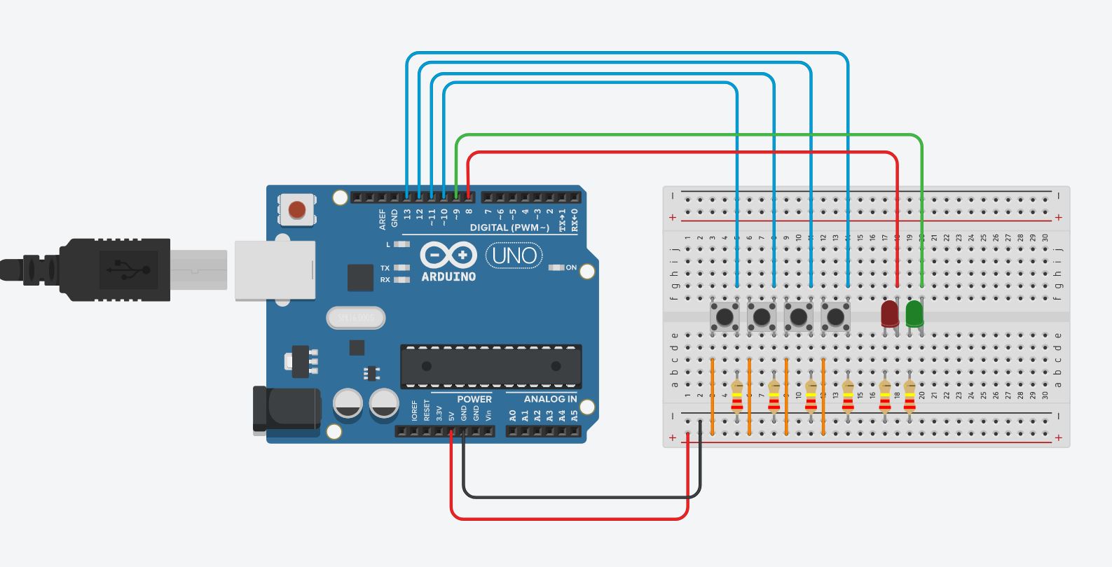
Circuit Diagrams:

Arduino Code (File):

https://www.dropbox.com/s/28b1s6tkrl9ltfu/Combination_Lock.ino?dl=0

Week 4: Button Combination Lock

The button combination lock assignment commissioned us to make a electric lock that could be “unlocked” when a predetermined combination was input into the Arduino processor.  I attempted this assignment in two different ways.

The first was engendered by an Instructables page, HOW TO: MULTIPLE BUTTONS ON 1 ANALOG PIN – ARDUINO TUTORIAL, through this way I gained a better understanding of how to set up the breadboard circuitry. However, the method failed as I was not getting a consistent return on data from each button.

Assembly:

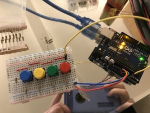
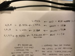
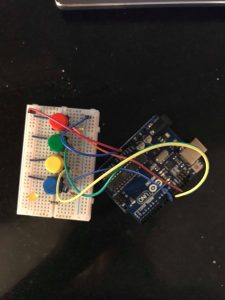
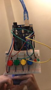
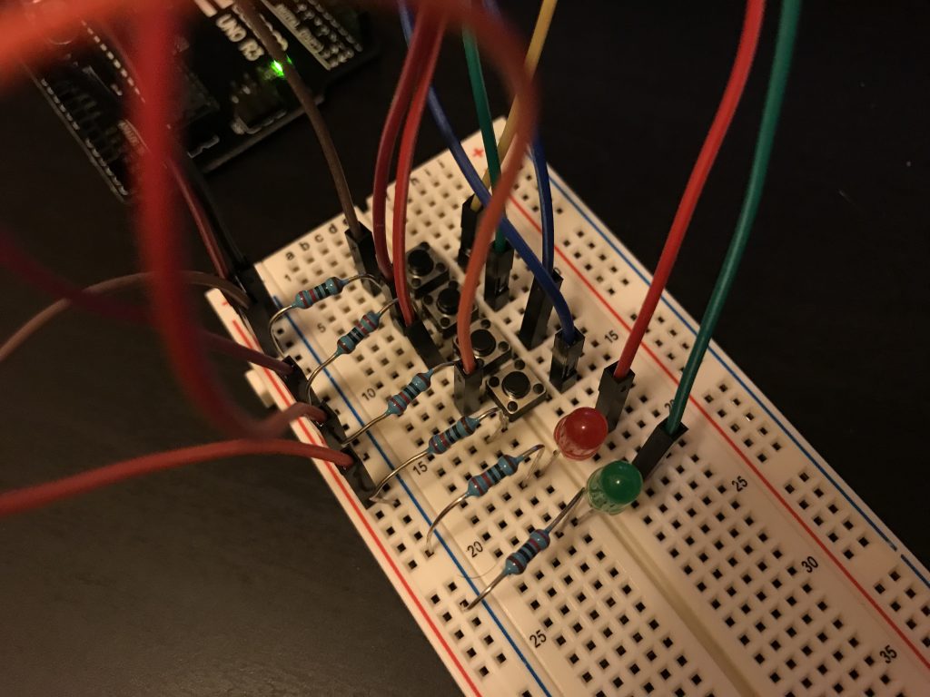
As seen in the pictures I set up the breadboard as the tutorial had indicated, using a resistor ladder, so that all the input could be sent through a single connection (0A). Unlike the tutorial, my return when each button was pressed was not a single identifying number, but a series of randomly repeating numbers. For example, the green button when pushed would show a random compilation string of the numbers 2,3, and 4. Thusly, I was unsure of how to proceed to associated the series to a variable.

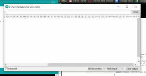
Also unlike the tutorial, I found that the resistors they recommended, 1x 1K, 2K, 3K and 10K resistors, were too strong, resulting in more inconsistent returned numbers from the buttons. When I changed the resistors to those of a weaker level the series of numbers returned had less 0s and a more unique set (if you will). In the image below of the Arduino monitor screen you can see a set of 4 randomly occurring numbers. Starting from the left; blue button was 1, 9, 8, 2, and 0, yellow button was 1, 2, and 3, green button was 2, 3, and 4, and lastly red button was 6, 5, and 1.

Materials:

  • Arduino uno
  • Breadboard
  • 4x button sw
  • 4x leds (yellow,red,blue,green)
  • 4x 330 Ohm (or 220Ohm) resistors
  • 1x 1K, 2K, 3K and 10K resistors

How it works/ Issues:

According to the Instructable, “for every time a button is pressed, the Arduino receives an analog value from 0 to 1023. ” Depending resistance to each button this value changes, which is what I saw when I changed the resistance to a lower value. The architect of this assembly found that they would recognize which button was pressed by the analoged value from the resistor (1st button: 1013
2nd button:1004, 3rd button: 995, 4th button: 871), however like previously state, mine did not have a consistent return value.

http://www.instructables.com/id/How-to-Multiple-Buttons-on-1-Analog-Pin-Arduino-Tu/

void setup() {
Serial.begin(9600);
int buttonvalue;
pinMode(A0,OUTPUT);
const int ledPin = 13; //Pin 13 will have the LED light
}
void loop() {
  int sensorValue = analogRead(A0);
  Serial.print(sensorValue);
  delay(1000);
}
Since I don’t have much experience with code, nonetheless Arduino circuitry, I turned to a classmate for help. Together we recoded part of the arduino and changed the board to where there was no longer a single connection transporting the data, but one direct connection per button. The coding was mostly his doing and its subsequent dissection allowed me to see the synatx of his method.

Assembly:

  1. Using a bread board and two jumper wires connect the ground to GND on the Arduino and the power to 5V on the Arduino.
  2. Take out the four buttons and place them abreast one another and in the center of the board.
  3. On the ground side take out the 4x resistors (800ohm to 1,400 ohm) and per button, connect the ground to the button leg (leave space for the jumper wire).
  4. Using 4x jumper wire, place the wire in between the button and resistor and connect to a subsequent digital pin (13-10).
  5. Connect another 4x jumper wires from the other side of the button to the power.
  6. The 220 ohm resistors will connect into ground and orient them towards the center of the board.
  7. Place the LED (negative side) along side the resistor.
  8. One the positive side of the LED place the remaining two jumper wires and connect them to digital pins (8 & 9).

Materials:

  • Arduino uno
  • Breadboard
  • 4x button sw
  • 12x jumpers
  • 4x resistors ranging from 800ohm to 1,500ohm
  • 2x 220 ohm resistors
  • 2x LED (green and red)

How it works/ Issues:

In comparison to the Arduino code the physical circuitry was relatively easy to put together. Nevertheless it still doesn’t work, so I can’t for certain say my composition is functional. Each button is connected to it’s own jumper cable which is then connected to an individual pin on the Arduino. Using const int I associated the pin number (13-10) to a correlating button (green, red, blue, yellow). The resistor were connected into ground while the end cable was connected to power to complete the circuit. Since each isolated pin could relay data directly to the board, in theory, it made identifying the buttonpush easier, from this point the Boolean code and conditionals would determine a combination and process the data. This part was out of my depth, but my classmate’s help and contributions have allowed me to gain a better understanding of how the Arduino processes information.

Button Combination Lock

I will include the code with my dissection.

Chyelle’s Dissection of Arduino Code Syntax