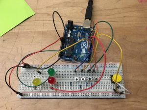
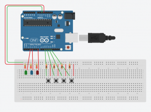
Utilize 4 small buttons to create a combination locker
Use 1 big button to submit & reset
Green and red led to show whether the passcode is right or not
Yellow led to show each correct press
The lock passcode: 4213
Core components
4 * small buttons
1 * big button
3 * LED (red, yellow, green)
5 * 10k ohms resistors
3 * 220 ohms resistors
Wires & jumpwires
Arduino board
How it works
Press the button sequentially once a time with no repeat
If it is in right sequence, yellow led will blink
Press the yellow big button to submit (and it will reset at the same time)
Green led means unlocked (right), red led means locked (wrong)
Problems/bugs
If you don’t start with 4, and then you pressed 4, then press the buttons in a right sequence, the locker can still be unlocked.
Goal of the project : By utilizing a sequence of button presses, make multiple leds to radiate. Like a concept of lock, each led represents whether it is locked / unlocked.
Core components : 4 buttons, 4 x 10K ohms resistors, yellow and blue leds, 2 x 220 ohms resistors, breadboard, arduino board, jumper wires
How it works : I made a circuit that enables a certain rule of button press to make each led shine. When button 1 and button 3 are pressed at the same time, yellow led emits, and if button 2 and button 4 are pressed at the same time, blue led emits.
Problems encountered : A little confusion with making a circuit for multiple buttons – where to the power and output connections go – but I figured out with reminding the basic mechanism of buttons.
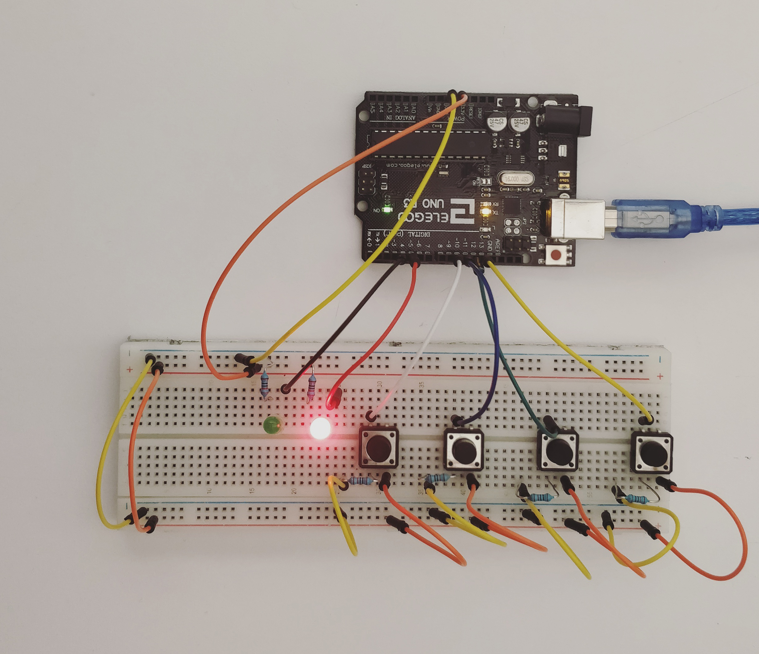
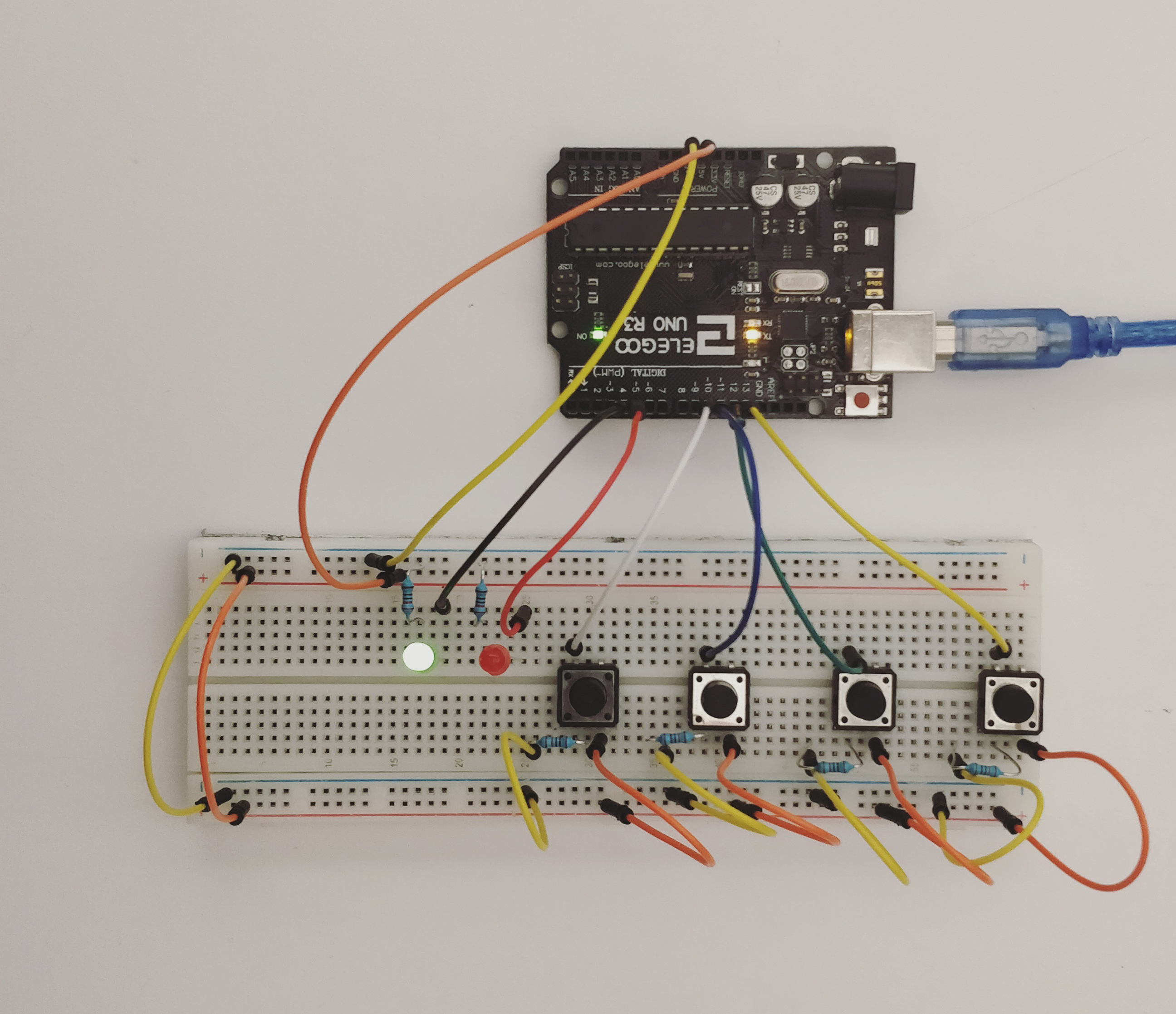
This Week’s assignment was to create a circuit for a combination lock. The default state for this circuit is locked (represented by a red LED). When all four buttons are pressed in the right sequence, the circuit becomes unlocked (LED turns green).
List of Materials
1 x Elegoo Uno R3
1 x Full sized breadboard
4 x Pushbuttons
2 x LED’s (Red and Green)
Resistors: 4 x 220 Ohms (for the LEDs), 2 x 10K Ohms (for the buttons)
Jumper wires
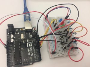
Description of assembly
Connect both sides of the breadboard to each other. The ground to the ground and the power to the power using jumper wires.
Connect the ground side of the breadboard to the GND pin, and the power side to the 5V pin, on the Arduino.
Add pushbuttons to the breadboard, where one of the legs is connected to the power source, the adjacent leg to the ground (through the resistor). Connect the leg opposite the ground to a digital pin. When the pushbutton is not pressed, the digital output pin is connected to the ground and returns a LOW state. When it is pressed, the circuit gets complete, electricity flows through it, and a HIGH state is recorded.
Arrange the LEDs with the shorter leg connected to the ground through a resistor and the longer leg to the digital pins.
Upload the code to the Arduino IDE.
Debug, check connections and keep working on iterations.
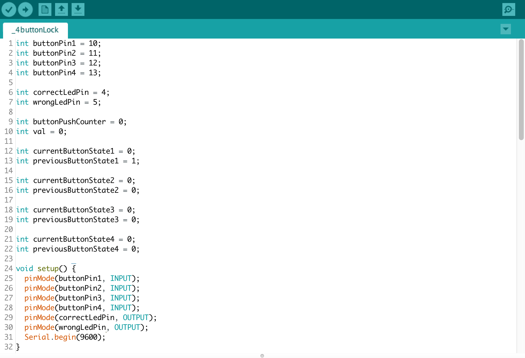
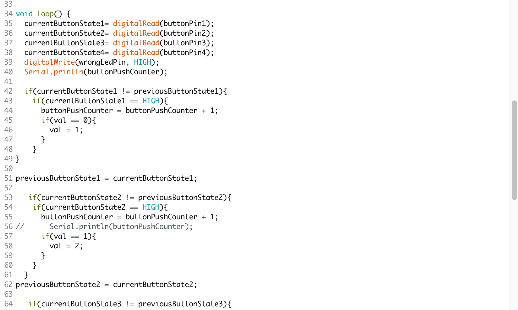
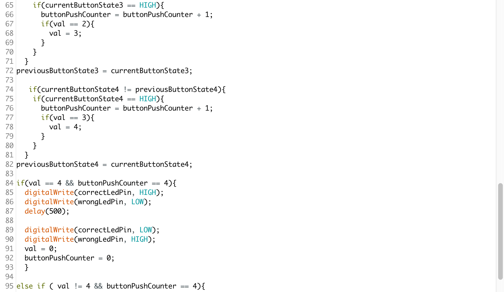
How it works
The Arduino code, has nested if loops that sequentially check whether certain conditions hold true. It first checks whether button 1 is pressed, if it is, then it checks if button 2 is pressed and so on and so forth. There are two variables being used buttonPushCounter and val. The first checks whether any button is being pressed and the other is to determine the order in which they are being pressed. It is only when all the four buttons are pressed in the right order that the green LED lights up.
Challenges
Setting the circuit was not as challenging as was getting the code to work. I encountered a problem with my buttonPushCounter because it wasn’t registering button presses. I used the console to debug and realized that it was because I had defined the variable globally as well as locally which was interfering with the functioning of the code. The solution is to either define it globally or to use something called static int to define it within the scope of the void loop.
What I am still struggling with is using the same button twice in the code. At present, I can program different combinations of button presses, but I cannot get the counter to reset every time a button is pressed.
Code
//Referenced from code available on the Arduino forum
This week, our homework was to make a lock that can be unlocked (green light will light up) with a specific pin or password with Arduino. And inserted with the wrong password or pin, a red will light up indicating the password is wrong.
Quick description of assembly and list of core components
1x Arduino board
1x Medium breadboard
1x Green LED
1x Red LED
1x Blue LED
4x Buttons
2x Resistors (220 ohms) for resistors
4x Resistors (10K ohms) for buttons
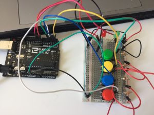
How it works
There are 4 buttons and 3 LED lights (green, red, and blue). The blue light will be on when the lock is ready. To unlock the lock, the pin is 0, 0, 1, 2, 3. Once you press the right pin, the lock will unlock with a green light that indicates it is unlocked. When you press the wrong pin, the red LED will light up and flashes.
Any problems you encountered and/or solved
I had problems setting up the sequence and had a hard time assigning them to the right buttons. After debugging my circuit and with the explanation and help others, I was able to get the sequence right.
The goal was to set a combination that lights the green light and closes the red one.
I used 2 buttons (a red one and a blue one), two led lights (green and red) and 4 resistors (2 ok 220Ohm and 2 of 10KOhm).
The combination is red>red>blue>red>red.
The goal of the project was to create a locker that opened (green light) when the right color code was pressed ( 4 different colours). The light must be red while the code remains wrong.
Quick description of assembly and list of core components
1x Arduino
1 x medium breadboard.
1x green LED
1 x red LED
4 x buttons
2 x resistors (220 ohms) – resistors
4 x resistors ( 10K ohms) – buttons
How it works
My proposal includes a counter that allows to keep tracking of the correct sequence thanks to validating certain if statements. At the end, green LED lights up, and after blinking and a short delay, red light turns ON again, and it’s locked again reseting the counter to start again.
Any problems you encountered and/or solved
I had problems to find the correct sequence that allowed to keep the good sequence. My counter kept reseting until I debugged the code.
The goal of this project is to build a combination lock that uses 4 buttons and LEDs that indicates lock status.
Components:
red led x1
green led x1
blue led x1
button x4
resistor(200Ω) x4
resistor(10kΩ) x4
arduino board & breadboard
How it works
Users need to input a combination of 4 numbers to open the lock. The blue button is a reset light which will light up 5 seconds after the right code is input (The lock is locked again, the input is reset ) or the wrong four numbers are input (meaning please try again, the input is reset). The red light means a wrong code is pushed and the green light means the code is correct.