PART 1
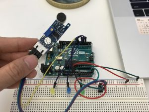
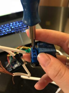
IMG_1516
Goal:
I’m making a sound visualization project using Arduino as an input and Processing as an output.
Arduino: I’m using a photocell sensor to detect the light from the environment and map the data to use in Processing to control the alpha value of the floating points.
Processing: I’m using minim library to visualize the audio file and created 300 points floating with it.
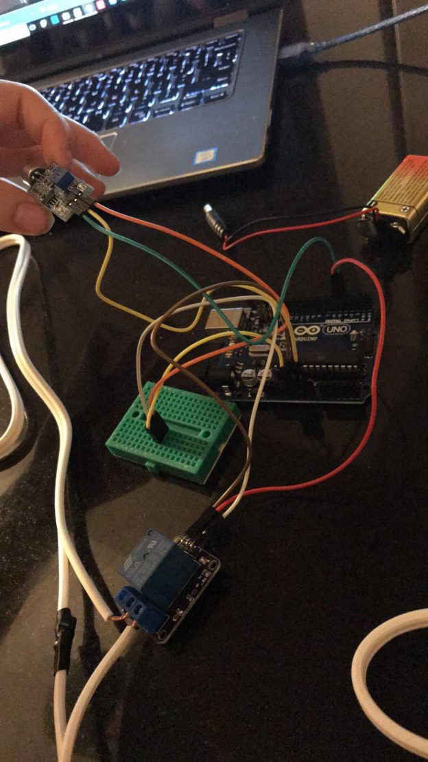
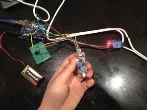
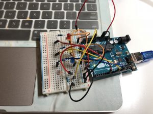
Core components
1* photocell sensor
1 * 10k resistor
Wires & jumpwires
Arduino board
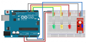
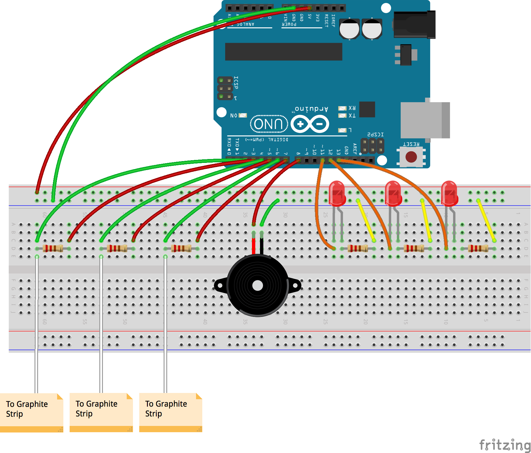
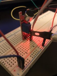
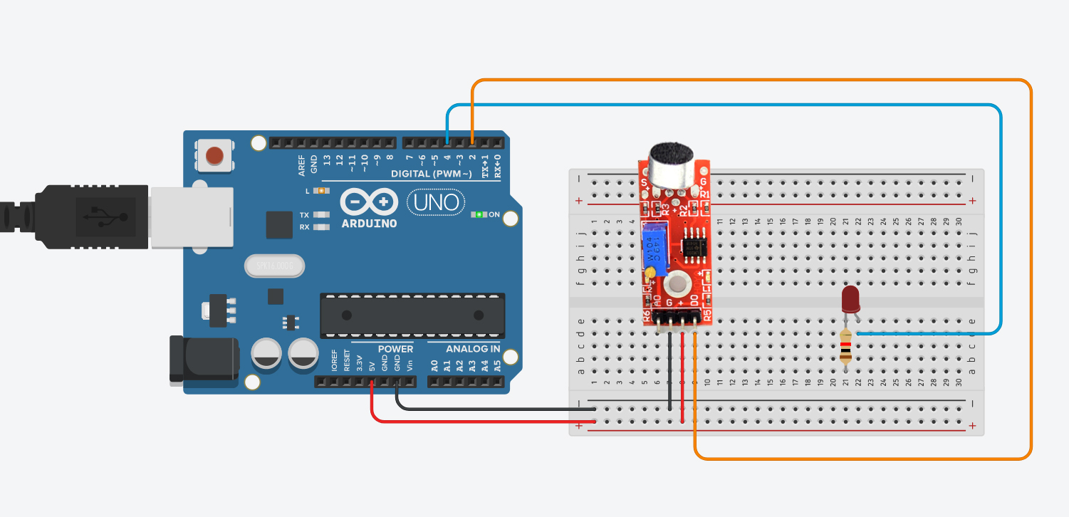
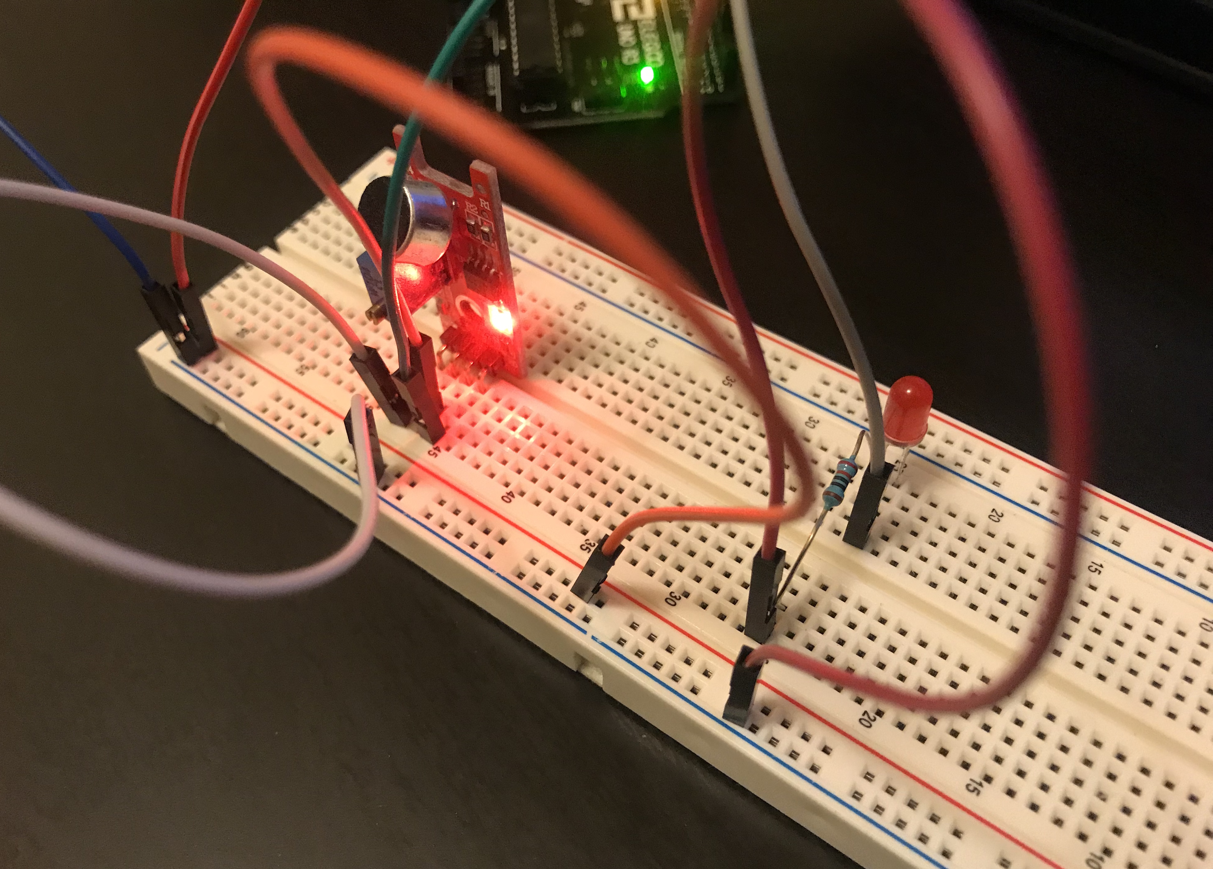
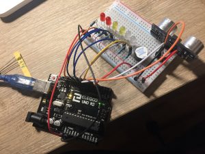
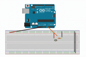
Circuit/Schematics
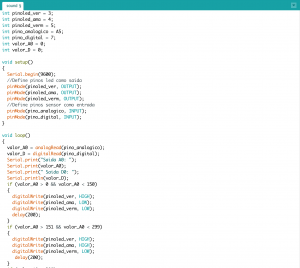
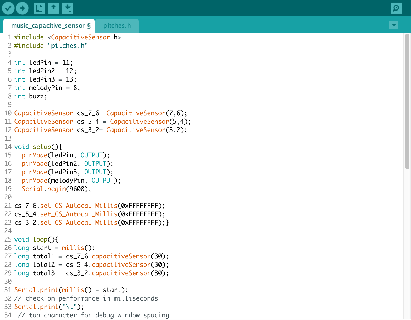
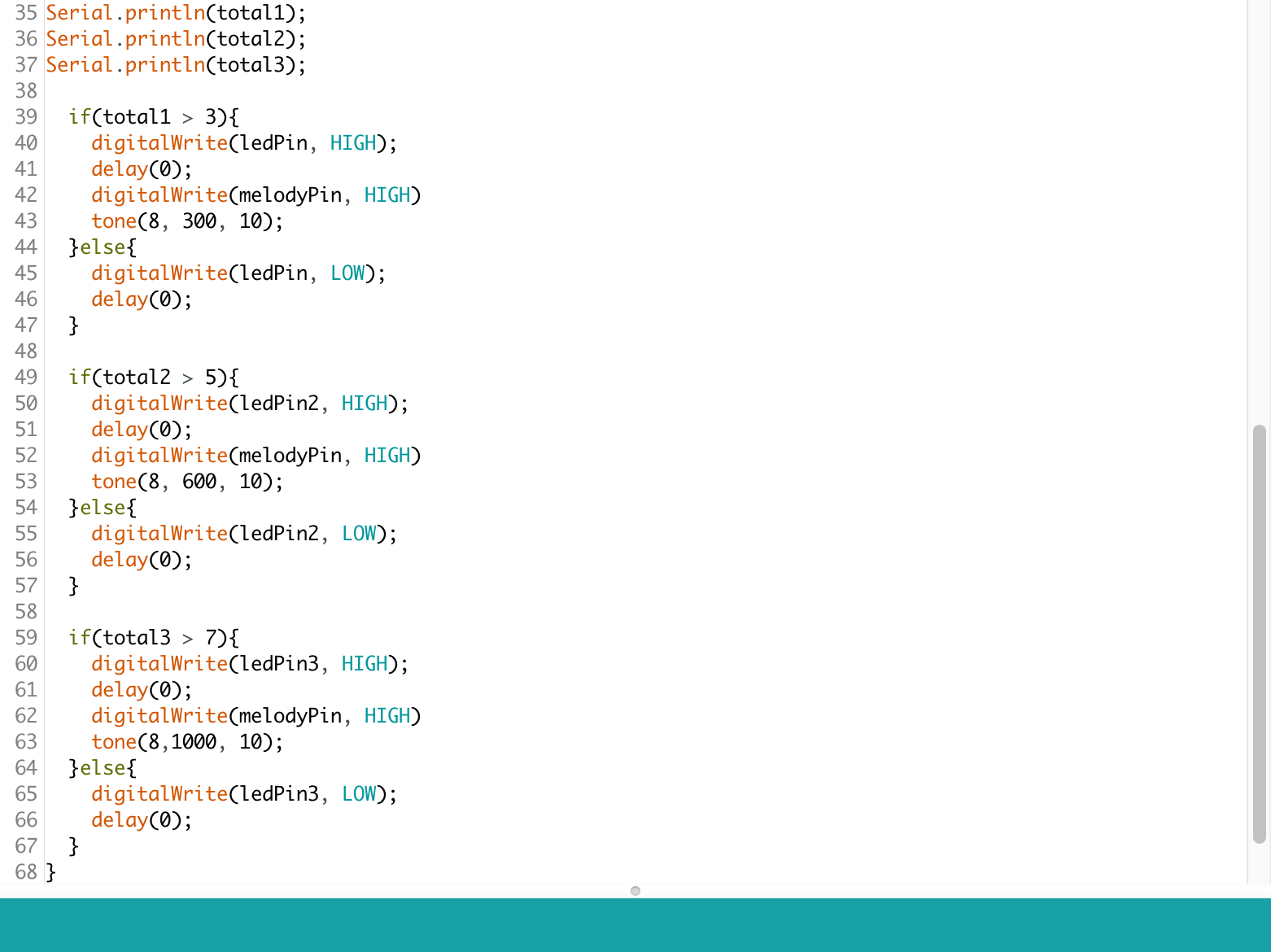
Code:
Arduino: StandardFirmata
Processing:
import cc.arduino.*;
import org.firmata.*;
import processing.serial.*;
import ddf.minim.*;
import ddf.minim.analysis.*;
import cc.arduino.*;
Minim minim;
AudioPlayer song;
FFT fft;
Arduino arduino;
int num = 300;
PVector[] posArray = new PVector[num];
float pTime = 0;
float vel;
PVector[] noiseArray = new PVector[num];
int sensorPin = 0;
int sensorVal = 0;
float newSensorVal;
void setup() {
size(1000, 800, P3D);
minim = new Minim(this);
println(Serial.list());
arduino = new Arduino(this, Arduino.list()[1], 57600);
song = minim.loadFile(“1.mp3”, 512);
song.loop();
fft = new FFT(song.bufferSize(), song.sampleRate());
for (int i = 0; i < num; i++) {
float r = random(300,400);
float theta = random(TWO_PI);
float y = r*sin(theta);
float x = r*cos(theta);
noiseArray[i] = new PVector(x, y);
posArray[i] = new PVector(0, 0);
}
arduino.pinMode(sensorPin, Arduino.INPUT);
}
void draw() {
background(0);
pushMatrix();
translate(width/2, height/2);
scale(1.5);
fft.forward(song.mix);
noStroke();
println(arduino.analogRead(sensorPin));
sensorVal = arduino.analogRead(sensorPin);
newSensorVal = map(sensorVal,800,960,50,250);
//float a= random(100,200);
fill(random(0,255),random(0,255),random(0,255),newSensorVal);
for (int i = 0; i < num; i++) {
ellipse(posArray[i].x, posArray[i].y, 2, 2);
}
popMatrix();
update();
}
void update() {
float time = millis()*0.001;
float dt = time – pTime;
println(dt);
pTime = time;
float level = song.mix.level();
float fftVal = fft.getBand(300);
vel = map(fftVal, 0, 0.1, 0.05, 0.5);
for (int i = 0; i < num; i++) {
noiseArray[i].x += vel * dt;
noiseArray[i].y += vel *dt;
float xScale = map(noise(noiseArray[i].x), 0, 1, -1, 1);
float yScale = map(noise(noiseArray[i].y), 0, 1, -1, 1);
posArray[i].x = xScale * 300;
posArray[i].y = yScale * 300;
}
}
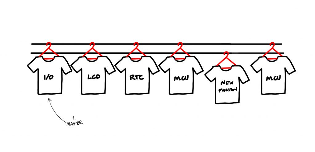
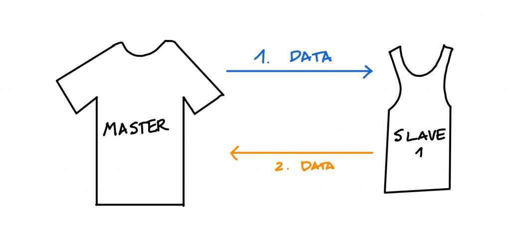
PART 2
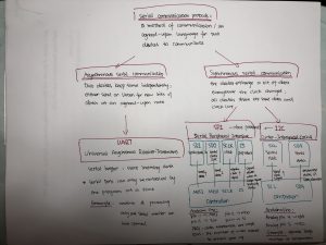
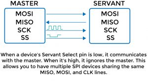
Communication protocols: