- Brief: After this week’s lesson about light and sound I wanted to find a project that would further enlighten me to the logistics of how sound can be sensed and a subsequent automatic action can be taken. The first idea for a project that came to mind was to use a vibration/sound sensor to sense a sequence of wave lengths and subsequently signal this information to us by lighting up a line of LED lights with escalating levels of brightness. Though that was a bit much for a novice like myself. Ergo, I thought pursuing something of a practical and simpler fashion could be very informative, like turning on a light fixture by clapping.
- Goal: Conclusively, the goal of this weeks assignment is to assemble an arduino system that can sense a clap and automatically turn on an LED/light. Hopefully I will be able to personalize the clap rhythm or code that will turn on the light.
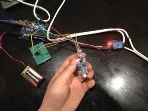

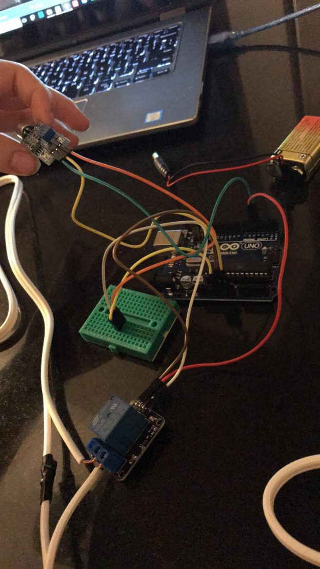
- Assembly:
- Materials:
- Arduino Board, Relay Module, Sound Sensor, 9V Battery, F to M Jumper 6x, M to M Jumper 1x, Breadboard, Battery Cable, mini screw driver, wire strippers and two prong light fixture.
- Materials:
- Clap Sensing Arduino Light Switch Tutorial (<– Really amazing)
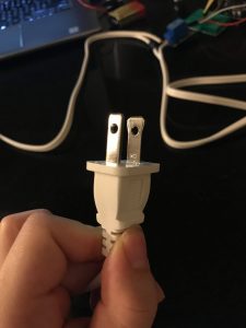
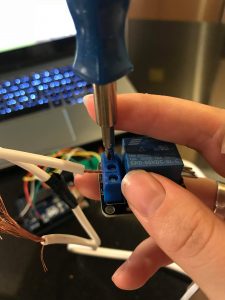
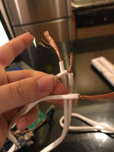
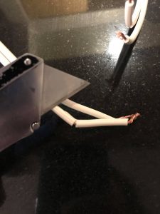
- 1) Using your light fixture, expose the live wires
- you can leave the neutral wire alone, but it might make the length crooked.
- The live wire is the side that runs along the the more narrow prong of the outlet head.
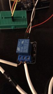
- 2) After exposing the wire connect them to the relay open pins of the relay module.
- 3) Using 3x of the F to M jumpers, connect the Relay GND pin will be connected to the GND pin of the Arduino.
- The Relay VCC pin will be connected to the +5V pin of the Arduino.
- The Relay INPUT pin will be connected to the Digital 5 pin of the Arduino.
- 4) Connection of the Sound Sensor uses 3x of the F to M jumpers
- The Sound Sensor VCC pin will be connected to the +5V pin of the Arduino.
- The Sound Sensor OUT pin will be connected to the Digital 4 pin of the Arduino.
- The Sound Sensor GND pin will be connected to the GND pin of the Arduino.
- 5) Connection of the breadboard, using 1x M to M jumper
- Abreast from one another connect the M to M jumper to the 5v pin in the Arduino.
- Connect the relay module’s VCC: positive power supply M jumper end to the bread board (abreast the 5v connection).
- Connect the VCC: positive power supply of the sound module to the breadboard abreast the module jumper.
- 6) Up load code:
- 7) Connect 9V battery with cable to Arduino.
- 8) Plug in light and turn on.
- 9) Start clapping because now you got light!
- 1) Using your light fixture, expose the live wires
- How it works: Video
- Problems:
- The biggest problem I had with this project was due to my own lack of knowledge. In the very informative and simple video tutorial of how to make a clap sensing light switch the architect does not articulate which of the two wired cables are neutral and live (probably because most people know, but I didn’t). Accordingly, my first time around I didn’t connect the live to the relay module, instead I connected the neutral so initially my light didn’t turn on at all. I was stumped and very discouraged by the 2nd time I had taken it apart and put it back together again. The next day I did some research on how to fix cords chewed up from pets and during this tutorial I learned that in addition to my neutral and live connection problem I probably damaged the wires post stripping. By the third trial I had made a solid connection and miraculously the light turned on and could sense my clapping… snapping, and any high pitched double ” bang.”
- Images:
7) Insert the Read More quicktag, otherwise your post will go one forever.