Category Archives: Week 6: Displaying Information through Light + Sound

Communication protocols: UART and SPI

Electronics are all about interlinking individual circuits to create a larger system. In order for the individual circuits to exchange information/ “talk” with each other it is important that they speak the same language (or technically speaking share a common communication protocol).

Just as we have developed languages that we use for communication, electronic circuits speak in the binary language- a long string of information- made up of only 0’s and 1’s.

But even when they speak the same language, they should have a channel of communication between them (Think of it as the air that helps us talk to each other by transferring the vibrations caused by sound waves). There are hundreds of communication protocols that help circuits talk to each other. They can be broadly categorized into parallel or serial communication protocols.

Continue reading

Sound and Light Week 6: Part 1


  • Brief: After this week’s lesson about light and sound I wanted to find a project that would further enlighten me to the logistics of how sound can be sensed and a subsequent automatic action can be taken. The first idea for a project that came to mind was to use a vibration/sound sensor to sense a sequence of wave lengths and subsequently signal this information to us by lighting up a line of LED lights with escalating levels of brightness. Though that was a bit much for a novice like myself. Ergo,  I thought pursuing something of a practical and simpler fashion could be very informative, like turning on a light fixture by clapping.
  • Goal: Conclusively, the goal of this weeks assignment is to assemble an arduino system that can sense a clap and automatically turn on an LED/light. Hopefully I will be able to personalize the clap rhythm or code that will turn on the light.

  • Assembly:
    • Materials:
      • Arduino Board, Relay Module, Sound Sensor, 9V Battery, F to M Jumper 6x, M to M Jumper 1x, Breadboard, Battery Cable, mini screw driver, wire strippers and two prong light fixture.
  • Clap Sensing Arduino Light Switch Tutorial (<– Really amazing)
    • 1) Using your light fixture, expose the live wires
      • you can leave the neutral wire alone, but it might make the length crooked.
      • The live wire is the side that runs along the the more narrow prong of the outlet head.
    • 2) After exposing the wire connect them to the relay open pins of the relay module.
    • 3) Using 3x of the F to M jumpers, connect the Relay GND pin will be connected to the GND pin of the Arduino.
      • The Relay VCC pin will be connected to the +5V pin of the Arduino.
      • The Relay INPUT pin will be connected to the Digital 5 pin of the Arduino.
    •  4) Connection of the Sound Sensor uses 3x of the F to M jumpers
      • The Sound Sensor VCC pin will be connected to the +5V pin of the Arduino.
      • The Sound Sensor OUT pin will be connected to the Digital 4 pin of the Arduino.
      • The Sound Sensor GND pin will be connected to the GND pin of the Arduino.
    • 5) Connection of the breadboard, using 1x M to M jumper
      1. Abreast from one another connect the M to M jumper to the 5v pin in the Arduino.
      2. Connect the relay module’s VCC: positive power supply M jumper end to the bread board (abreast the 5v connection).
      3. Connect the VCC: positive power supply of the sound module to the breadboard abreast the module jumper.
    • 6) Up load code:
    • 7) Connect 9V battery with cable to Arduino.
    • 8) Plug in light and turn on.
    • 9) Start clapping because now you got light!
  • How it works: Video
  • Problems:
    • The biggest problem I had with this project was due to my own lack of knowledge. In the very informative and simple video tutorial of how to make a clap sensing light switch the architect does not articulate which of the two wired cables are neutral and live (probably because most people know, but I didn’t). Accordingly, my first time around I didn’t connect the live to the relay module, instead I connected the neutral so initially my light didn’t turn on at all. I was stumped and very discouraged by the 2nd time I had taken it apart and put it back together again. The next day I did some research on how to fix cords chewed up from pets and during this tutorial I learned that in addition to my neutral and live connection problem I probably damaged the wires post stripping. By the third trial I had made a solid connection and miraculously the light turned on and could sense my clapping… snapping, and any high pitched double ” bang.”
  • Images:

    • 7) Insert the Read More quicktag, otherwise your post will go one forever.

UART Examination Week 6

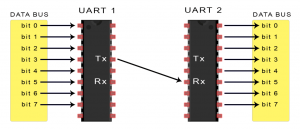
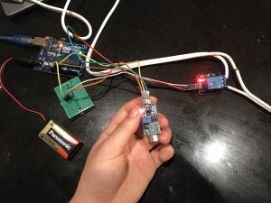
Contrary to the assignment, a UART also known as the Universal Asychronous Receiver/Transmitter is not a communication protocol, but a physical circuit that transmits and receives data through the serial port. Though similarly to protocol like SPI and I2C, UART is another method to transmitting and receiving serial data from other devices. This transaction of serial data or dialog between devices is an electronics form of language, in other words communication protocols. UART (according to circuitbasics) is a relatively old communication method and like stated in its name, is asychronous language. In computing, Asychronous indicates a dialog between UARTs is defined by a start and stop notification in a data series versus a clock that synchronizes the output to the receiving UART. A UART and a I2C can send a limited amount of bits (1 start bit, 5 to 9 data bits, an optional parity bit, and 1 or 2 stop bits), these messages are called packets.

How a UART works is that it will receive data in a parallel form (all at once through multiple points) and the UART(1) will translate the data into a packet to which it will transmit the data to the receiving UART(2) in series (one after the other on a single line). The receiving UART(2) will then translate the data (discarding the start and stop bit) and send it in parallel to the external data bus.

One of the more popular advantageous attributes that UART features includes: it uses only two wires to transmit data to another device (TxD: Transmit Data –RxD: Receive Data), uses a parity bit for error checking, data packet can be changed, contains a serial buffer (extra storage space so it can do other tasks while waiting for data), and is a pervasively used and accepted method (found in most processors). These attributes make UART a great communication protocol/mode, nevertheless their convenience do have their foibles. Some disadvantages include the data frame is limited to 9 bits, does not support multiple slaves/ master systems, and the baud rates (reading speed) must be within 10% of the transmitting and receiving UARTS.

Most (all) processors have a UART because of their simplicity in communication transmission, some processors include Raspberry Pi and computers. Though in more sophisticated CPUs the UART chip has become dispensable because the software of the outputted transmission can regulate the process instead of hardware, this technique is called bit-banging.  (not completed yet)