This week’s assignment was to creatively rethink how sound and/or light could be incorporated into projects by modifying the input sensors. I decided to work with capacitive sensing because I love the possibilities it provides. It allows us to make our own sensors and enhances the quality of the interactive experience.
List of Materials
1 x Elegoo Uno R3
1 x Full sized breadboard
1 x Piezo buzzer
3 x Graphite strips
3 x LEDs
Resistors: 3x 220 Ohms (for the LED), 3 x 1 Megaohms (for capacitive sensing)
Jumper wires
Fritzing diagram
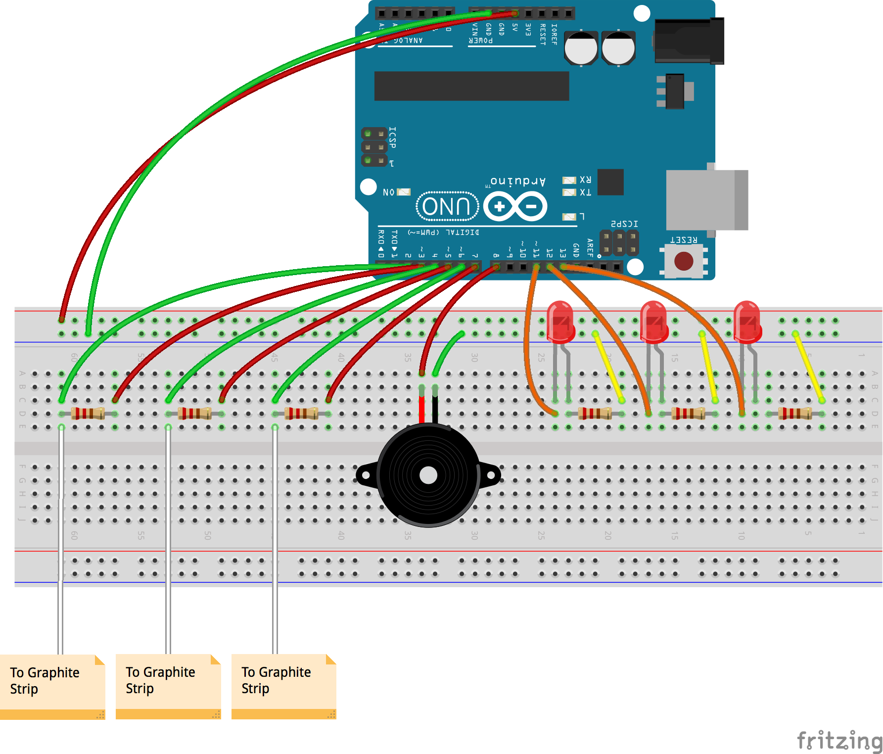
Description of assembly
- Connect the ground side of the breadboard to the GND pin, and the power side to the 5V pin, on the Arduino.
- Add three LEDs to the circuit, with the shorter legs connected to the ground via 220 Ohm resistors, and the longer legs to digital pins 11, 12 and 13 respectively. Connect the Piezo buzzer with the ground connected to the ground of the breadboard, and the power to digital pin 8. Both the LEDs and the buzzer act as the output, reacting to changes in the capacitive sensors.
- To make one capacitive sensor, connect two jumper wires on either end of a 1 Megaohm resistor to digital pins 2 and 3. The resistor leg, connected to pin 2, should also be connected through the jumper wire to the graphite strip.
- Repeat step 3 two more times, using digital pins 4, 5 and 6,7.
- Upload the code to the Arduino IDE.
- Debug, check connections and keep working!
How it works
Capacitive sensing works on the principle of using a conductive material to complete the circuit. This circuit works as follows. A high resistance of the order of a megaohm is placed on the breadboard, both ends of which are connected to say, digital pins 2 and 3. Digital pin 3 acts as the input and allows a steady stream of electrons to flow through the circuit. The resistor inhibits the flow and only lets a small number of electrons pass through the other end. The other end in addition to being connected to a digital pin is also attached to a jumper wire. When we touch the metallic end, we pass on a large number of electrons from our body to the circuit. The Arduino can sense this change and can be coded to control an output by defining a threshold value.
Iterations
Graphite conducts electricity and this property can be utilized in interesting ways. I shaded some bits of paper with an HB pencil and connected them to the breadboard so that they could act as switches. For the first iteration I decided to make an instrument where, on pressing each key, one would hear a different, pre-programmed song through the Piezo buzzer. I first tried with the example code melody to see whether all three switches were working individually. On graduating to coding different songs, I had limited success.
This further led me to think about how a user could make their own music. On pressing a key, they would hear a tone, akin to a piano. The various sequences and combinations could culminate in unique tunes. I had trouble associating one LED to one graphite switch. After multiple iterations, it turned out to be a glitch in the code which I then rectified.
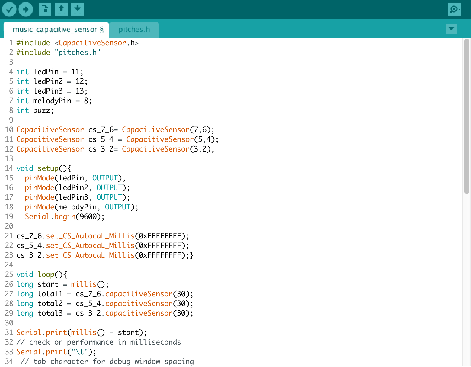
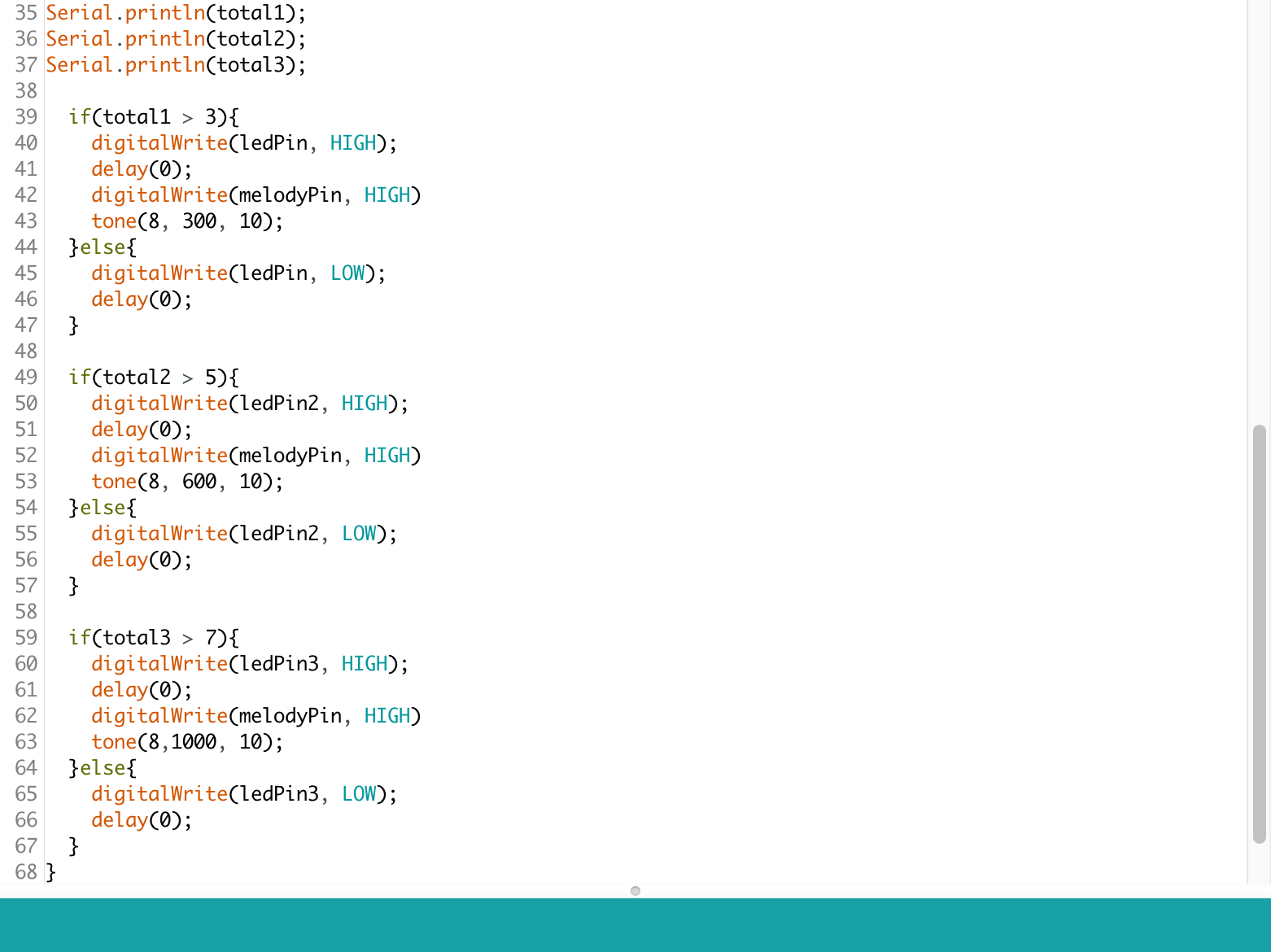
Code