I want to create wireless connection between Arduino and OpenFrameworks using Ada.
Description:
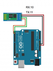
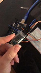
To connect two bluetooth module together, and send data between each other you have to have both module for master and module for slave. In this time, I only connect the module with my laptop, so I only need module for slave. (H05 can be both master and slave, H06 can only be a slave).
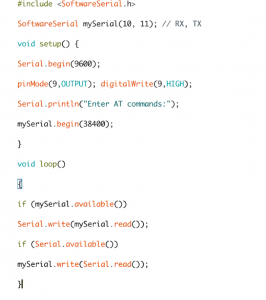
How it works: You push the button on H05 module to enter AT mode, and then reconnect VCC and upload the Arduino code. Then connect OpenFrameworks to Arduino using Serial connection.
Problem:
The connection was not stable enough, and the data sent to OpenFrameworks delayed too long.
instruction for wireless assignment is to choose one of the wireless topics covered in class and put it to practice for use in everyday life. I chose Infrared LED (IR) as the topic I want to explore. With the IR(Emitter) and Photodiode(Receiver), I can create a simple IR detector by change the amount of infrared light received by the photodiode with my hand or any barrier to light up the indicator led. This simple idea is widely used in our daily life, for example, alarm system to detect the intruder.
Components list:
arduino UNO x1
breadboardx1
photodiode x1
IR LED x1
LED x1
resistor 300ohm x2 (IR, LED)
resistor 10k x1 (photodiode)
wires
How it works:
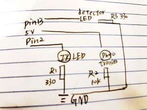
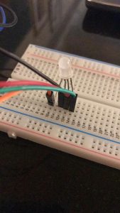
An IR sensor consists of two parts- the emitter circuit and the receiver circuit. This is collectively known as a photo-coupler or an optocoupler. The emitter is an IR LED and the detector is an IR photodiode. The IR photodiode is sensitive to the IR light emitted by an IR LED. The photodiodes resistance and output voltage change in proportion to the IR light received. This is the underlying working principle of the IR sensor.
The type of incidence can be direct incidence or indirect incidence. Indirect incidence, the IR LED is placed in front of a photodiode with no obstacle in between. In indirect incidence, both the diodes are placed side by side with an opaque object in front of the sensor. The light from the IR LED hits the opaque surface and reflects back to the photodiode. In this project, I found out the direct incidence is way more effective so I put emitter and receiver in front of each other.
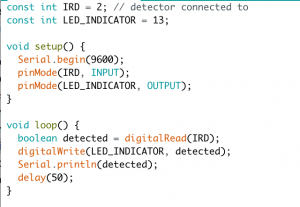
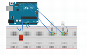
circuit and code :
the code is very simple, using the boolean function to detect and light up detector LED
Troubleshooting:
note that photodiodes and emitter LED can look exactly the same (transparent led), don’t mess them up. Also, to get the best result, do put receiver and emitter as close as you can.
The goal of the project was to control remote an LCD display.
I started connecting the LCD and then the remote receiver.
When trying to test the remote control it got burned.
My original hypothesis was that the potentiometer was responsible but I believe the component was defective because the remote control battery exploded a few hour later. Continue reading →
Goal: To create a wireless notification device. The mailbox in my apartment building is on the first floor. However, I live on the fourth floor. It takes extra effort to go downstairs to check the mailbox only to discover that nothing has arrived. So, this project is an Arduino Bluetooth-enabled device that sends a notification to my desktop and my cell phone that the mailbox has been opened, thus alerting me to the presence of mail. Continue reading →
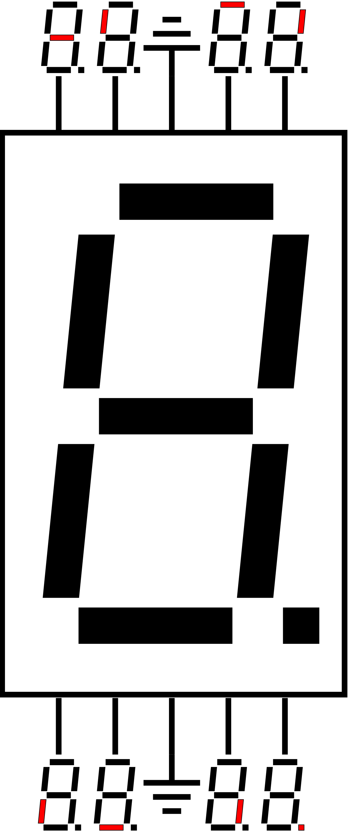
Goal of this project : I would like to make a sample version of TV’s display of indicating channels and volume and remote control. Using IR receiver module and remote control, it will enable users to control channels (number) and volume (up and down).
Assembly description : I made a circuit that IR receiver module and 7-segment display to be connected to the arduino uno. IR receiver module has three legs – one (G) is for ground, the other one (R) is for Vcc, and the last one (S) is for signal. I connected the signal pin to pin 11, and set an additional led in pin 13 so that user could know the signal is receiving or not (We could also know through the tiny light on IR receiver module). For 7-segment display, the each pin represents each different stroke that constitute a number (including period “.” to confirm the exact direction of numbers). It has total 10 pins, 8 of them representing strokes are connected to each different output pins, and two of them are connected to the ground.
Anode to 5V If Strip Gnd of driver to gnd of Arduino
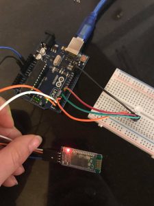
Blue Tooth Connection to Arduino:
Rx to pin 12 of Arduino
Tx to pin 11 of Arduino
vcc to 5v
gnd to gnd
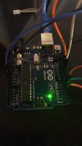
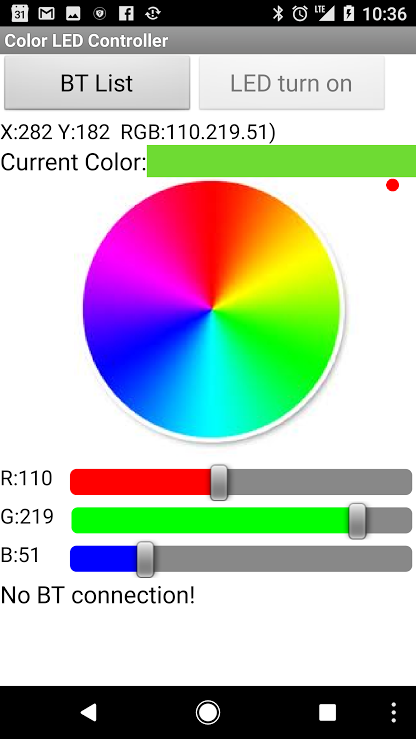
How it works: As the concept goes, via bluetooth and the correct smartphone app I will be able to control the color of the LED wirelessly. The designer of this project went into depth about the logistics of how the RGB LED actually changes colors by describing how the Arduino uses a digital representing Analog signal that varies pulse to mimic a PWM (Pulse Width Modulation). By using a digital representing Analog signal the colors are able to seem like they are gradually changing even when they are not.
Problems: I faced a plethora of problems with this assignment. From jumping to project to project trying to find a source that didn’t rely on Android applications or Google Play to simply the code refusing to upload onto the Arduino “programmer not responding.” To say the least I had many difficulties. Though I believe the most prevalent can be found in the fact the alternative applications I downloaded onto my phone (Iphone) to control the LED via blue tooth could not connect. I’m not sure if it was because of the code/ Arduino blue tooth or the app not being compatible with the program, regardless it didn’t work. I ended up accidentally burning out my RGB LED, so I will try again tomorrow with another application!
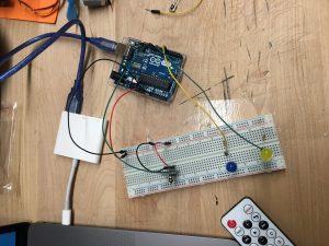
I want to control the light in different rooms.
Use IR sensor to control the brightness of LED, and turn on/off of LED
Core components
1* IR sensor
1* remote control
2* LED
2 * 220 ohms resistors
Wires & jumpwires
Arduino board
Circuit/Schematics
How it works
Button 1 : switch on/off of blue LED
Button 2 : switch on/off of yellow LED
Button + : increase brightness (++ 50)
Button – : decrease brightness (- – 50)
Two LEDs have different on/off state, but have the same brightness.
Problems
Two LEDs can’t be adjusted separately
The remote control is inaccurate
Choose one of the wireless topics covered in class and put it to practice for use in everyday life. For example, use the IR sensor with a remote control to make a fan for a hot summer day.
Document your project in action and post to the class blog, including the list of materials used, a circuit schematic, and notes regarding wins and challenges.