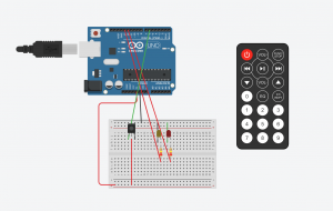
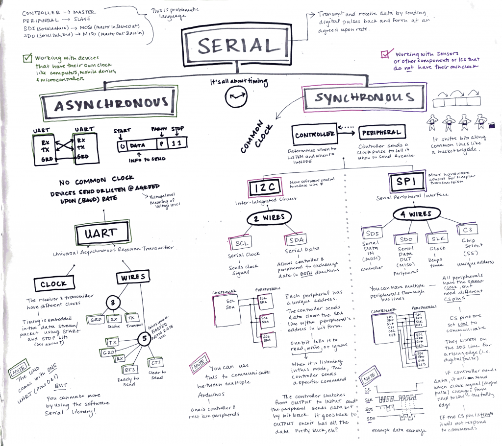
Video:
Goal: The goal of this week’s wireless assignment is to be able to control a RGB mood light via smartphone blue tooth.
Core Components:
- Arduino Uno
- Bluetooth module
- RGB LED
- 4x M-M Jumper
- 4x M-F Jumper
- Bread Board
- Recommended Android Application: Color LED Controller
- Apple Alternative Application (Has not worked… yet)
Assembly:
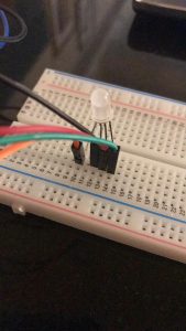
RGB LED to Arduino:
- Red to Pin 3 of Arduino
- Blue to Pin 5 of Arduino
- Green to Pin 6 of Arduino
- Anode to 5V If Strip Gnd of driver to gnd of Arduino
Blue Tooth Connection to Arduino:
- Rx to pin 12 of Arduino
- Tx to pin 11 of Arduino
- vcc to 5v
- gnd to gnd
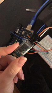
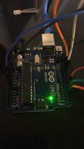
How it works: As the concept goes, via bluetooth and the correct smartphone app I will be able to control the color of the LED wirelessly. The designer of this project went into depth about the logistics of how the RGB LED actually changes colors by describing how the Arduino uses a digital representing Analog signal that varies pulse to mimic a PWM (Pulse Width Modulation). By using a digital representing Analog signal the colors are able to seem like they are gradually changing even when they are not.
Problems: I faced a plethora of problems with this assignment. From jumping to project to project trying to find a source that didn’t rely on Android applications or Google Play to simply the code refusing to upload onto the Arduino “programmer not responding.” To say the least I had many difficulties. Though I believe the most prevalent can be found in the fact the alternative applications I downloaded onto my phone (Iphone) to control the LED via blue tooth could not connect. I’m not sure if it was because of the code/ Arduino blue tooth or the app not being compatible with the program, regardless it didn’t work. I ended up accidentally burning out my RGB LED, so I will try again tomorrow with another application!
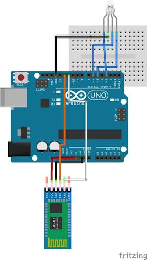

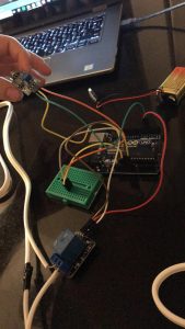
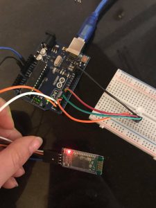
Images of Physical Circuit:
Sources: SmartPhone Controlled RGB MOOD Light
Continue reading →
