Concept + Goals: With this project, I sought to create an interactive exhibit that complements the ‘Me Too’ and ‘Time’s Up’ movements. These were my guiding design questions:
Background : After careful consideration of which will the best way to deliver this story of domestic abuse, I chose to build a sound system with virtual visualization. I created the survivor’s house and character with camera movement in Unity. I built 4 spaces of her house – her bedroom, living room, dining room, and a large room they used as a study. I put 4 soundtracks of her testimony in each space, along with other ordinary domestic sounds I recorded separately. After doing so, 4 video experiences were created.
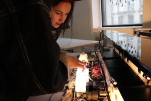
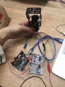
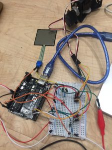
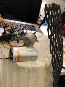
The goal of the project- Try the basic set up for final project form, and two robotic plants with different motion included. One is made with the stepper motor(Ferns) and the other one is muscle wire(Flytrap). In this iteration, I want to test the light and visual effect of this project as well as differentiate random and systematic movement of robotic plants. Also, one important implementation of this iteration is to add the interaction part, using Kinect and Unity to communicate with Arduino, audiences can interact with this set by walking around in the room.
Main components:
Arduino UNO
Xbox Kinect 2
0.012mm muscle wires
tip120
330-ohm resistor
12v stepper motors
motor shield for stepper motor
12v 6a power source
How it works:
For the demo can see the playtest video below. Kinect– using the infrared camera to detect audience’s body skeleton and find the x, y, z-axis. Unity– using the c# program to enable the trigger function when audiences touch the certain area (there are five little yellow people models spread on the screen representing different location). When the models being triggered, Unity will send a byte to the serial monitor in Arduino. Arduino– in code, there is a processing message which will start to heat up the wire and rotate the motor, by typing “on” in the serial monitor, the function loop will start to run. To conclude, by connecting these three different platforms, I can achieve an indirect interaction without using a sensor. For the final setup, the audience will not see the unity interface so that they can just walk around, being captured by Kinect, and the robotic plants will move based on their movement without notice.
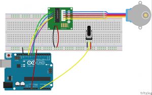
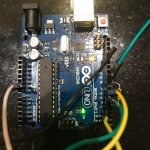
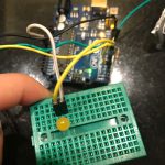
Circuit and CODE:
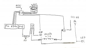
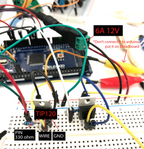
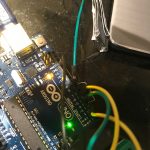
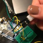
The following circuit includes the detail for connecting muscle wire correctly, note that there are two sides of muscle wires, one side should go to the middle leg of the transistor(TIP 120), and the other should go to the positive side, which is 12v 6a (+) in this circuit. The other two legs of transistor go separately to GND & resistor- Pin, the reason for pin leg output can actually control the transistor and open the circuit for electricity to go through the wire. Be very aware of the external power source, don’t connect it to Arduino unless you want to burn it. Just connect positive and negative side to breadboard like how you use 9V battery to power up the circuit.
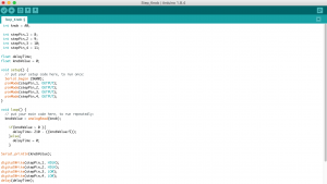
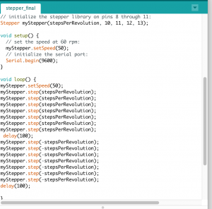
CODE in Arduino:
#include <Stepper.h>
const int stepsPerRevolution = 200; // change this to fit the number of steps per revolution
// for your motor
// initialize the stepper library on pins 8 through 11:
Stepper myStepper(stepsPerRevolution, 8, 9, 10, 11);
String buf;
char c;
int flower=6;
int flower1=4;
int flower2=5;
int led = 2;
void setup() {
pinMode(flower,OUTPUT);
pinMode(led, OUTPUT);
// set the speed at 60 rpm:
myStepper.setSpeed(60);
// initialize the serial port:
Serial.begin(9600);
}
void loop() {
while (Serial.available() > 0) {
c = Serial.read();
if (c == ‘\n’) {
processMessage();
buf = “”;
} else {
buf += c;
}
}
}
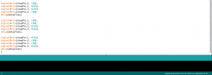
void processMessage() {
Serial.println(“processMessage”);
if (buf.equals(“on”)) {
for(int i=0;i<6;i++){
// step one revolution in one direction:
Serial.println(“clockwise”);
myStepper.step(stepsPerRevolution);
delay(500);
// step one revolution in the other direction:
Serial.println(“counterclockwise”);
myStepper.step(-stepsPerRevolution);
delay(500);
}
}
}
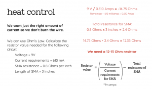
Problem encountered:
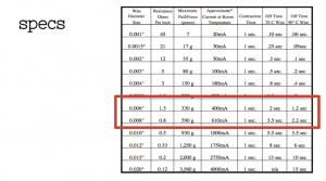
I spent a lot of time to caculate and test the right amount of electricity for the wire. Using the specs chart of wire and the formula of voltage caculation from computational craft class slides really help me alot.
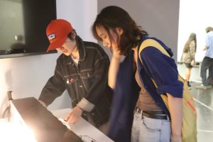
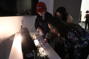
For the playtest plan, I record a simple demo video to show the interaction. I would like to know people’s reaction toward the movement of plants, it’s interesting to look at or not. Also, I am curious about if they are aware of what interaction they are adding up to this system.
Use single stepper motor to driver belt moving, and test out the durability of stepper motor.
Description:
This particular prototype, I used 5V stepper motor to test our if one motor is powerful enough to lead the belt moving, and also used a potentiometer to test the rate of speed control. Moving forward, I need to choose the materials of making the belt to in consideration of the right amount of friction.
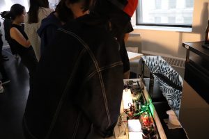
How it works: The stepper motor controlled by knob drive the bar with wheels to rotate, which lead the belt attached to them to move.
Problem:
Plywood had lots of frictions which requires a much stronger power of motor to lead the movement.
Materials:
Arduino UNO R3 x 1
Breadboard x 1
Stepper motor x 1
Stepper motor driver x 1
Potentiometer x 1
Wires
18 x 24 inch Plywood for laser cut
Wood bar
Paper
Connection Diagram:
Code:
2) Your play-testing plan and desired feedback.
The Major Major Exhibition will be where the playtest happen. I want feedbacks from users :
Whether my core messages are successfully delivered?
How was the user experience?
What do they think I could have done more?
Was the interaction effective in delivery desired information?
Do they feel confused with the interaction with my piece?
I do not mind help each users out during the test, but the explanation shall as little as possible.
Based on user test, they think the final outcome of using fingerprints is very effective way of expressing human efforts inside the process. Also, the interaction and watching the little objects move along the belt by their interaction is very interesting and engaging. What could be improved was the form of interactions. For example, the level of difficulties of the interaction, and a more symbolic form of interaction will be more educational. Also, some users suggest I could also involve interactions on digital screen. For example, some interactions to trigger animation or video showing the sophistication of logistics system.
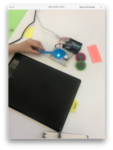
This project has three parts, color sensor, Wacom digitizer, digital screen. This installation will set up on the darkroom for the better user experience, when a user comes into the room they can find some objects placed around the color sensor, they may try them at first them find the other color they need in the surrounding.
Prototype:
Playtesting:
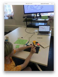
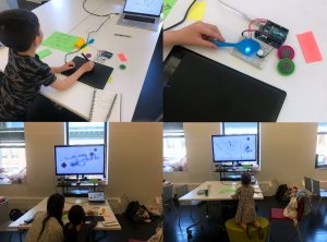
I attended the PLAYTECH (in D12) activity for the children and teenagers user testing, I use my conceptual prototype to test more than ten young people at a total. The main part I test is the stability of the sensor, the playability of the function, the unexpected outcomes from a different kid.
I provide the RGB sensor which can catch the color you input form the objects with a tip note, also I put a Wacom board and digital pen beside the sensor to test how they react with them.
Process:
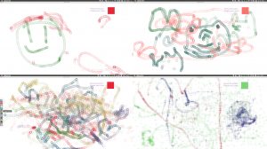
Outcome:
Feedback:
Teenagers (youngest 10 years old) can understand the usage of the project better, children (under 6 years old) always ignore what I said, and barely use the button to control the color, and their painting has less meaning and structure.
All testees are all express their passion and interest through the test.
Some teenagers suggest if people can erase the image they draw.
They want more options of brush pattern, for example, cartoon character, mixed shapes.
Two teenagers think they need to press many times button to draw a satisfied painting which is a little bit confused sometimes.
Iteration:
Adding more brush shapes, you may can create by yourself or you can choose one of them.
Goal of the project and/or desired interaction
I hope to be able to press on a force pressure sensor to activate the camera for the face detection to track my motion and then turn the camera off by pressing on another force pressure.
Quick description of assembly and list of core components – Arduino x1
– Small Bread board x1
– Force pressure sensors x2
– Servo motor x2
– Jumper wires
– Resistors 220ohm x2
How it works
When you stand in front of the camera, it will not work but when you press on 1st pressure sensor, the camera will start tracking your motion and turn towards wherever you are moving. You can turn the camera off by pressing on the 2nd pressure button.
Any problems you encountered and/or solved
I have encountered many problems with the code where the code tends to be stuck in an IF statement and another problem I still face is that the code only runs once. After running once, it won’t activate again unless I restart the Arduino and processing sketch again. I still haven’t figured out what is the problem since the code looks all correct.
Who will you playtest with?
I will playtest with my fellow peers from Design & Technology program and possibly some other same age peers from different programs in Parsons.
How will you get their consent? I will ask them if they are willing to test out a quick interaction and give me some feedback.
What feedback do you want? I want the interaction of my model doll dog to be intuitive so I know where to exactly design my pressure sensor on my model dog.
What questions will you ask? What is the first intuitive response of placing your hand at (on my model doll dog)?
Where do you think you can press to activate music?
What information do they need to know before starting? I will give them a basic overview of my concept.
How much will you help them during the test? Aside from trying to give them a basic overview, I will try to let them figure out themselves. If they really need help, I will give them hints.
How will you debrief them? I will let them know what I’m really testing orally and ask them if they have any questions.
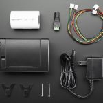
Goal: The next part of my prototype for my fortune teller was to get the Arduino thermal printer functioning and I did. With that being said the components of just the play-test for the thermal printer include;
A mini thermal receipt printer – with cables and plastic mounting shims
A roll of 50′ long thermal receipt paper – the perfect amount for the thermal printer. BPA-free.
5V 2A power supply – an ideal supply for powering the thermal printer (and anything else that can use 5V power
2.1mm DC jack adapter – makes it easy to attach the power supply to the printer
3x MM jumper wires
Assembling the thermal printer was a little challenging due to the site leaving out some essential pieces of information like how/where the F jumper cables for VH, GND, RX and TX are supposed to be oriented as well as the key instruction to strip the VH and GND wires to connect to the DC cable adaptor. However, lucky for me I had a friend who had experience with the Arduino thermal printer and was able to guide me through it.
Assembly:
Plug in the GND (black) and VH (red) F wires into the printer
Cut off the open end of the Red and black wires to expose the metal inside.
Using the DC adaptor put in the exposed black and red end of the wires
Make sure they are oriented correctly
Plug in the GND (black), RX (yellow) and TX (Green) wires into the printer
Using the 3 MM jumper wires attach them to the open end of the GND, RX and TX cord.
Insert the TX (green) wire into the digital ~5 pin of the Arduino
Insert the RX (yellow) wire into the digital ~6 pin of the Arduino
Insert the GND (black) wire into the GND (any of them) of the Arduino
Change the baud rate from 19200 to 9600 by accessing the source code.
If your printer test page shows ‘BAUDRATE: 9600’, you’ll need to make a small change to the library source code.
Go into your computer files where the Thermal Printer Library is being stored and using a text editor (Notepad, etc.) open the file Adafruit_Thermal.cpp
Ctrl-F ‘BAUDRATE’ and change this line from 19200 to 9600.
Save and exit.
Though since this code has components that conflict with my capacitive sensor code I needed to make some adjustments. I changed the RX (yellow) input pin from ~6 to ~3.
Problems/Issues: Originally when I did this (change the pin from ~6 to ~3) the LED light and the capacity was working however after I tested the printer the LED no longer responded to the capacitor. Though, as stated in the video, the LED light isn’t essential to the project it is still a sign that there might be a problem with the physical system itself. As of right now I am looking at ways to integrate the capacitive code into the thermal printer code, but as a novice in coding I’m not sure how to do this syntactically correct. I have an appointment Friday (4/20 lol.) with the Learning Center to help me over this part of the project.
Play-Test Feedback:
To think about:
Who will you playtest with? I will playtest with anyone who is available and willing. There is not criteria or prerequisite that needs to be met by the participants.
How will you get their consent? Their willingness to touch the capacitive sensor is all that is necessary.
What feedback do you want? I want people to experience a mediocre serendipity. It’s the equivalent to a fortune cookie so I have kind of low expectations on their reactions.
What questions will you ask? I will ask whether they enjoyed their fortune and if they have any ideas on how I could enhance the experience and output.
What information do they need to know before starting? None.
How much will you help them during the test? I will tell them to touch the pad.
How will you debrief them? I will tell them that this is my final project for a class and that is it an interactive art piece.
I migrated to Adafruit esp8266 module. The server now is successfully connecting to my iphone hotspot, pinging random IP numbers and when it get a success response it sends a request to a Geolocation API online service which provides the IP Geolocation information as a string of data.
What is left for the project is to edit the json data the server receives so it can easily identify the latitude and longitude coordinates and to create a light feedback. I will also create a tower design for my server.
A second stage for the project will be to create a custom laser projector that moves the laser point according to the IP coordinates. For this stage my objective is to have the relevant information to communicate to the laser.
Create a post with
1) The next iteration of your prototype.
Use the class documentation format. 2) Your playtesting plan and desired feedback.
To think about: Who will you playtest with? How will you get their consent? What feedback do you want? What questions will you ask? What information do they need to know before starting? How much will you help them during the test? How will you debrief them?