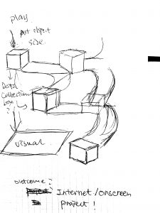
1) Next Iteration:
Use the class documentation format.
Goal:
Use single stepper motor to driver belt moving, and test out the durability of stepper motor.
Description:
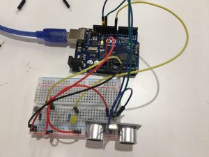
This particular prototype, I used 5V stepper motor to test our if one motor is powerful enough to lead the belt moving, and also used a potentiometer to test the rate of speed control. Moving forward, I need to choose the materials of making the belt to in consideration of the right amount of friction.
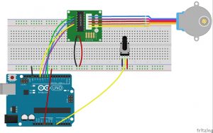
- How it works: The stepper motor controlled by knob drive the bar with wheels to rotate, which lead the belt attached to them to move.
Problem:
Plywood had lots of frictions which requires a much stronger power of motor to lead the movement.
Materials:
- Arduino UNO R3 x 1
- Breadboard x 1
- Stepper motor x 1
- Stepper motor driver x 1
- Potentiometer x 1
- Wires
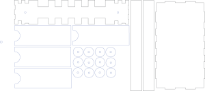
- 18 x 24 inch Plywood for laser cut
- Wood bar
- Paper
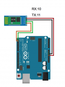
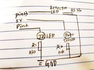
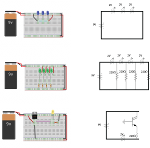
Connection Diagram:
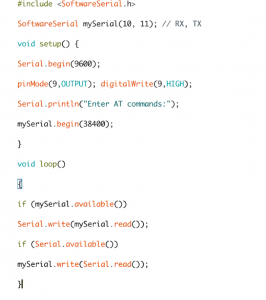
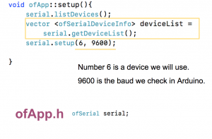
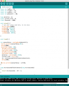
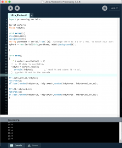
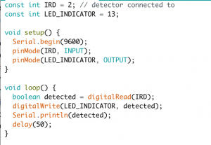
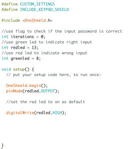
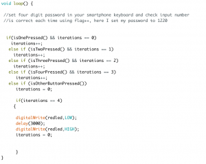
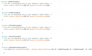
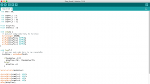
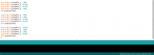
Code:
2) Your play-testing plan and desired feedback.
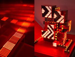
The Major Major Exhibition will be where the playtest happen. I want feedbacks from users :
- Whether my core messages are successfully delivered?
- How was the user experience?
- What do they think I could have done more?
- Was the interaction effective in delivery desired information?
- Do they feel confused with the interaction with my piece?
I do not mind help each users out during the test, but the explanation shall as little as possible.

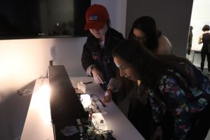
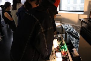
Based on user test, they think the final outcome of using fingerprints is very effective way of expressing human efforts inside the process. Also, the interaction and watching the little objects move along the belt by their interaction is very interesting and engaging. What could be improved was the form of interactions. For example, the level of difficulties of the interaction, and a more symbolic form of interaction will be more educational. Also, some users suggest I could also involve interactions on digital screen. For example, some interactions to trigger animation or video showing the sophistication of logistics system.