Category Archives: Uncategorized

WEEK12-Further Iteration

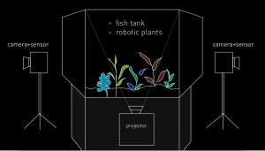
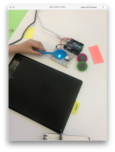
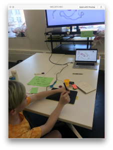
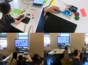
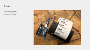
The goal of the project- Try the basic set up for final project form, and two robotic plants with different motion included. One is made with the stepper motor(Ferns) and the other one is muscle wire(Flytrap). In this iteration, I want to test the light and visual effect of this project as well as differentiate random and systematic movement of robotic plants. Also, one important implementation of this iteration is to add the interaction part, using Kinect and Unity to communicate with Arduino, audiences can interact with this set by walking around in the room.

Main components:

Arduino UNO

Xbox Kinect 2

0.012mm muscle wires

tip120

330-ohm resistor

12v stepper motors

motor shield for stepper motor

12v 6a power source

How it works:

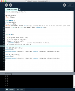
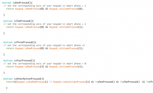
For the demo can see the playtest video below. Kinect– using the infrared camera to detect audience’s body skeleton and find the x, y, z-axis. Unity– using the c# program to enable the trigger function when audiences touch the certain area  (there are five little yellow people models spread on the screen representing different location). When the models being triggered, Unity will send a byte to the serial monitor in Arduino. Arduino– in code, there is a processing message which will start to heat up the wire and rotate the motor, by typing “on” in the serial monitor, the function loop will start to run. To conclude, by connecting these three different platforms, I can achieve an indirect interaction without using a sensor. For the final setup, the audience will not see the unity interface so that they can just walk around, being captured by Kinect, and the robotic plants will move based on their movement without notice.
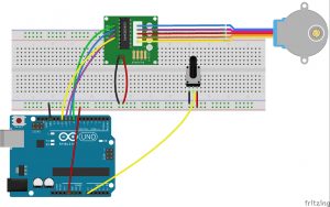
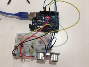
Circuit and CODE:

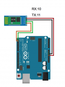
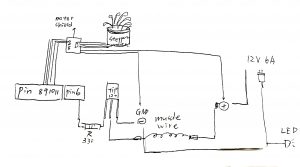
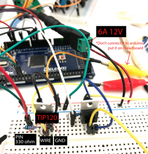
The following circuit includes the detail for connecting muscle wire correctly, note that there are two sides of muscle wires, one side should go to the middle leg of the transistor(TIP 120), and the other should go to the positive side, which is 12v 6a (+) in this circuit. The other two legs of transistor go separately to GND & resistor- Pin, the reason for pin leg output can actually control the transistor and open the circuit for electricity to go through the wire. Be very aware of the external power source, don’t connect it to Arduino unless you want to burn it. Just connect positive and negative side to breadboard like how you use 9V battery to power up the circuit.
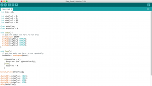
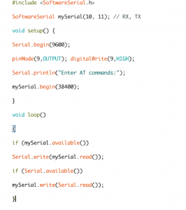
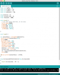
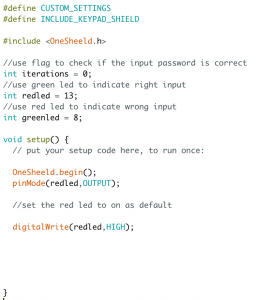
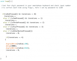
CODE in Arduino:

#include <Stepper.h>

const int stepsPerRevolution = 200; // change this to fit the number of steps per revolution
// for your motor

// initialize the stepper library on pins 8 through 11:
Stepper myStepper(stepsPerRevolution, 8, 9, 10, 11);

String buf;
char c;
int flower=6;
int flower1=4;
int flower2=5;
int led = 2;

void setup() {
pinMode(flower,OUTPUT);
pinMode(led, OUTPUT);
// set the speed at 60 rpm:
myStepper.setSpeed(60);
// initialize the serial port:
Serial.begin(9600);
}

void loop() {
while (Serial.available() > 0) {
c = Serial.read();
if (c == ‘\n’) {
processMessage();
buf = “”;
} else {
buf += c;
}
}
}

void processMessage() {
Serial.println(“processMessage”);
if (buf.equals(“on”)) {

//0.005″wire
digitalWrite(flower,HIGH);
digitalWrite(led,HIGH);
//
digitalWrite(flower1,HIGH);
digitalWrite(flower2,HIGH);
delay(3000);
digitalWrite(flower,LOW);
digitalWrite(led,LOW);
digitalWrite(flower1,LOW);
digitalWrite(flower2,LOW);
delay(8000);

for(int i=0;i<6;i++){
// step one revolution in one direction:
Serial.println(“clockwise”);
myStepper.step(stepsPerRevolution);
delay(500);

// step one revolution in the other direction:
Serial.println(“counterclockwise”);
myStepper.step(-stepsPerRevolution);
delay(500);
}

}
}

Problem encountered:

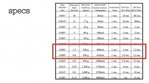
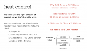
I spent a lot of time to caculate and test the right amount of electricity for the wire. Using the specs chart of wire and the formula of voltage caculation from computational craft class slides really help me alot.


For the playtest plan, I record a simple demo video to show the interaction. I would like to know people’s reaction toward the movement of plants, it’s interesting to look at or not. Also, I am curious about if they are aware of what interaction they are adding up to this system.

WEEK10-final project description and precedents

Final project description: 

  • I want to construct artificial, small-scale futuristic ecosystem under the scenario when synthetic biotic organisms are largely penetrated in human beings’ daily life.
  • This ecosystem will trigger interactions between human and simulated biotic organisms to raise a discussion of individual bio existence and the ecosystem at a large scale.
  • The interaction between audiences and this project should be indirect, which can echo the key concept for this project- A system that humans are party to, but not sovereign over.

Interaction/systems diagram:

Timeline with milestones: 

week 1 (4/3-4/8)- basic functionality

  • Communication between Arduino and  unity
  • Projection mapping visual test
  • Decision making: materials, project scales
  • Modeling the possible form of plants

week 2 (4/9-4/15)- Prototype

  • robotic plants prototype
  • project set up prototype
  • User test

week 3(4/16-4/22)- Iterations

  • modify the detail based on feedback
  • building circuits

week 4(4/23-4/30)-  Finalize

  • check the detailed implementation of project based on the exhibition place, equipment
  • troubleshooting physical computing part
  • polish the final project form

Precedents: 

EPIPHYTE CHAMBER by Philip Beesley

UNMAKEABLELOVE by Sarah Kenderdine & Jeffrey Shaw

petting zoo by minimaforms

sensory desserts by Erika Marthin 

 Synthetic Polleniser  by Michael Candy


Week 10 + 11 Final Project Idealization & Prototype

Project statement:

I want to explore the possibility of the alternative use of logistic methodology to create playful and informative experience for e-commerce customers. To tell them the logistic story with human efforts hidden behind each object they have

Interaction/systems diagram:


Timeline with milestones:

Mar 14 – Apr 1:

  • Decide type of data to collect
  • Decide medium of display
  • Technology Prototype/Test (data collection)
  • System design
  • Graphics design

Apr 5 – Apr 10:

1st protoype

Apr 10 – Apr 15:

2nd Prototype

Apr 16 – Apr 20:

3rd Prototype (optional) + design methodology and execution settled

Apr 25 – May 3:

Making

May 5: Major Major Exhibition

Materials list:

  1. LED UV light strip x 1
  2. warm white LED strips x 3
  3. Ultrasonic sensors x 1
  4. DC motors x 3, Stepper motors x 3
  5. Motor divers x 3
  6. Potentiometer x 3
  7. Trellis Keypad
  8. LEDs x n
  9. Buttons x 1
  10. 12V Adapter x 3
  11. 12V power supply
  12. Arduino UNO R3 x 3
  13. 9V Battery x 3
  14. Breadboard x 4
  15. Soldering kits
  16. Gluegun
  17. White and Black 24 x 18 in Acrylic sheets
  18. Acrylic tubes
  19. Plywoods

Precedents or references

  1. Nike CLC Installation: creates a series of low energy digital sculptures and light installation showcasing its operational efficiency, infrastructure system and live-feed data of the green energy consumption. 
  2. Ryan Gander’s Fieldwork: In this piece, a series of objects and assemblages that are by turns funny, macabre or banal revolving on a vast concealed conveyor belt. As they pass through an aperture in the gallery wall, the viewer is invited to speculate on the stories they tell, as well as their relationship to one another. 
  3. Multiverse, a long, conveyor-belt hall of the National Gallery of Art in D.C, gave me another example of how to create immersive visual experience along conveyor belt infrastructure.This piece used LED matrix on walls and ceiling to create an astonishing visual journey while people was riding on the moving walkway.

1st Prototype Iteration:

To test out work mechanism of conveyor belt, I laser cut plywood and paper, and build the very first simple prototype, which uses manual force as drivers to rotate the wheels that lead the belt to move.

Laser cut file

The success of this prototype allows me to move forward to test out technology feasibility of this mechanism, for example how much power of a motor or how many motors I need for moving how much weight of an object.

Week 8 Using Knob Control Stepper Motor

1. The difference between DC motor, Stepper motor, and Servo.

DC motor have a high speed of rotation, and once it is power charged, it will spin until the power is removed. Stepper motor has much precise control which have multiple magnetics installed inside to push the torque spin at  a specific direction and speed. Servo is like a DC motor with potentiometer installed inside for a speed control. It can rotate either clockwise or anti-clockwise.

2. Make a circuit using any of the new things you learned today- H bridges/ controlling high current loads OR work with a motor you haven’t worked with before OR Try making a circuit using multiple motors. Document it on the blog per the usual format.

Goal:

Using potentiometer to control speed of stepper motor

Description:

The value of potentiometer determines the speed of stepper motor.

  • How it works: the value from potentiometer serves as a analog input and determines the speed of stepper motor as a analog output.

Problem: 

The range of speed does not spread too much making it almost like two stages: stop and rotate. Also, the maximum speed of stepper motor was not high enough for a more conspicuous presentation.

Materials:

  1. Arduino UNO R3 x 1
  2. Breadboard x 1
  3. Stepper motor x 1
  4. Stepper motor driver x 1
  5. Potentiometer x 1
  6. Wires

Connection Diagram:

Code:


Week 7 Wireless Using Bluetooth

Goal:

I want to create wireless connection between Arduino and OpenFrameworks using Ada.

Description:

To connect two bluetooth module together, and send data between each other you have to have both module for master and module for slave. In this time, I only connect the module with my laptop, so I only need module for slave. (H05 can be both master and slave, H06 can only be a slave).

  • How it works: You push the button on H05 module to enter AT mode, and then reconnect VCC and upload the Arduino code. Then connect OpenFrameworks to Arduino using Serial connection.

Problem:

The connection was not stable enough, and the data sent to OpenFrameworks delayed too long.

Materials:

  1. Arduino UNO R3 x 1
  2. Breadboard x 1
  3. H05 module x 1
  4. 5V Battery x 1

Connection Diagram:

Code:

Arduino

Openframeworks


Week 5 Serial Connect with Processing

Goal:

I want to create a use ultrasonic sensor and a photocell to send data and bytes to processing, that allows me create a sense of controlling nature force on digital screen.

Description:

The sum of sensor values from ultrasonic and photocell determines the opacity and position of particles inside the fog.

  • How it works: people use hands to move around the ultrasonic sensor and use finger to cover the amount of light through photocell to control the position and opacity of fog particles on screen

Problem:

The data sent from Arduino to Processing are within certain range which are hard to be calculated and mapped precisely into the Processing sketches. Also, the bytes are not stable. (Also, I forgot to write code for LED, but I think it does not matter that much)

Materials:

  1. Arduino UNO R3 x 1
  2. Breadboard x 1
  3. Ultrasonic sensor x 1
  4. Photocell x 1
  5. 220Ω Resistors x 1
  6. Wires

Connection Diagram:

Code:

Arduino

Processing:

WEEK4-combination lock

Description of the project:

The goal of this assignment is to build your own combination locker with led and buttons. For me, I want a combination locker which can use keypad numbers as input and can be controlled by my cell phone. So I choose to use 1Sheeld module and it’s application to build my own combination locker.

List of components:

  • 1sheeld– a wireless shield which can easily attach to Arduino, with the customized application, you can use your cell phone to control Arduino.
  • Arduino Uno x1
  • Breadboardx1
  • 200-ohm resistor x1
  • Red led x1
  • jumper wires

How it works:

first of all, attach the 1sheeld to Arduino, and then connect LEDs to the pin assigned. After uploading the code to Arduino and 1sheeld. You can open up Bluetooth to search 1sheeld and connect to it. Then open the keypad shield in the 1sheeld application, enter the password you set to open the lock. In this project, I used red led to indicate “the locker is not opened”, and it was set it to be lighted up as default. When the user enters the right password, the red light should be turned off.

In the code part, using flag function (in here I put “iterations” to represent it ) to set your password. I set the password to “1220”, and every time you press the right keypad the flag will plus one. After fulfilling the 4 iterations (0~3), the red led should turn off.

Because of the flag function, the four-digit password should be checked each time, the wrong input such as “4593”, “2340” will not let the red light go off. See the following code for the details:

Any problems you encountered and/or solved:

My original intention is to use two different led lights, a red one for wrong and a green one for right. But no matter how hard I tried, 1 sheeld seems to not able control two LEDs at all. What I tried to debug including change all the components including the breadboard, LEDs, wires, and different pin. In the end, I only use one led to represent the lock status.


Week 1 Assignment from Slack

Video link: https://vimeo.com/128600307

Project description from the site:

A laser harp reimagined as a controller for an interactive audiovisual experience.

An installation that merges a futuristic musical instrument with a videogame.
Distract the beams and hit geometric objects to invoke hypnotizing chain reactions of light and sound, or just admire the experience of literally touching photons.
With “Klanglichter” you can now experience what you dreamt of in the 80s…

Made with Unity, Arduino and LOVE in the Cologne Game Lab by Tobias Kreter and Onat Hekimoglu
Shot on Blackmagic Pocket Cinema Camera with BMPCC Speedbooster and Contax Zeiss 28mm

How it works,

Using hands to interrupt the laser light from laser sensors, which triggers the visual and sound effects built in Unity.

Why I like it:

Because it explores the possibility of combining arduino with other source of platform, in this case Unity, which provides me much wider possibility and imagination in terms of the application of Arduino in projects. This also provides me with inspirations of how to build projects into a larger scales without wires and sensors heavily involved and displayed. Making a good or a smart use of one type of sensor, then you are good to go.

week 12 prototype and playtesting

This project has three parts, color sensor, Wacom digitizer, digital screen. This installation will set up on the darkroom for the better user experience, when a user comes into the room they can find some objects placed around the color sensor, they may try them at first them find the other color they need in the surrounding.

Prototype:

Playtesting:

I attended the PLAYTECH (in D12) activity for the children and teenagers user testing, I use my conceptual prototype to test more than ten young people at a total. The main part I test is the stability of the sensor, the playability of the function, the unexpected outcomes from a different kid.

 I provide the RGB sensor which can catch the color you input form the objects with a tip note, also I put a Wacom board and digital pen beside the sensor to test how they react with them.

Process:

Outcome:

Feedback:

        • Teenagers (youngest 10 years old) can understand the usage of the project better, children (under 6 years old) always ignore what I said, and barely use the button to control the color, and their painting has less meaning and structure.
        • All testees are all express their passion and interest through the test.
        • Some teenagers suggest if people can erase the image they draw.
        • They want more options of brush pattern, for example, cartoon character, mixed shapes. 
        • Two teenagers think they need to press many times button to draw a satisfied painting which is a little bit confused sometimes.

Iteration:

        • Adding more brush shapes, you may can create by yourself or you can choose one of them.
        • Editing the input color more accurate and stable.
        • Thinking about the erase function.
        • Simplify the button function.


Final Project Documentation

Design Statement

We are making a series of experimental prototypes that explore the ubiquitous but novel relationship between humans and objects. By reimagining the messages behind everyday objects, the project enables everyday objects to communicate and negotiate with us in their (possibly) preferable way.

Prototypes

1#Chair

2#Lamp

3#Printer