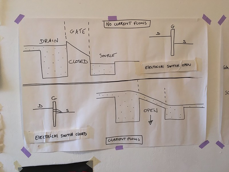
This is hands-down the BEST tutorial I have come across to describe how a transistor works and why it can act as a switch and signal amplifier. For those of you who are working with loads that need more current/voltage and therefore a transistor, I *highly* recommend you watch this immediately.
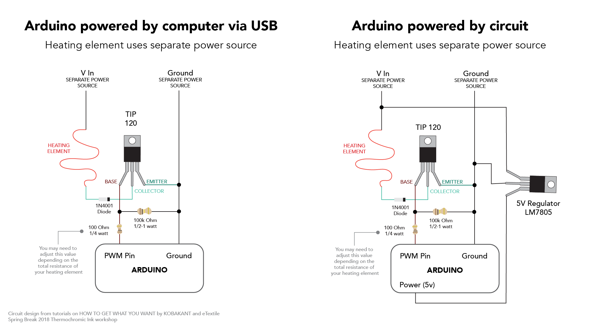
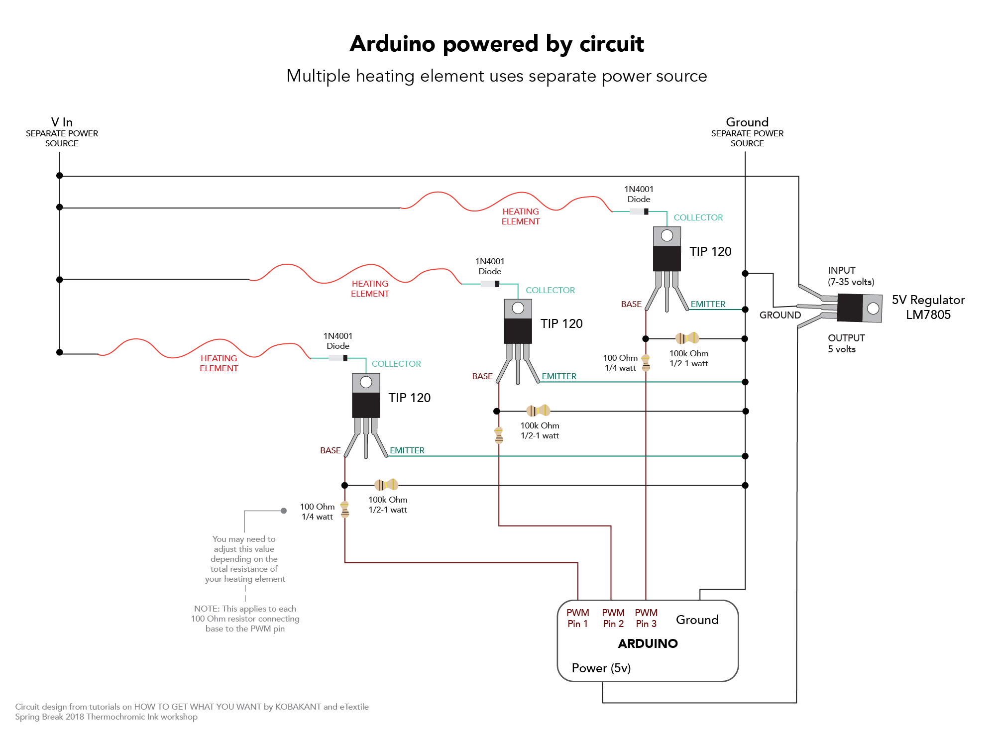
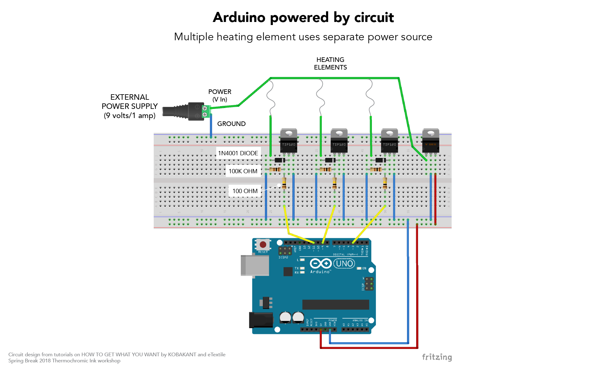
For those of you interested in heating circuits and thermochromic ink, below are some helpful circuit configurations. These circuits were taken from the Building Heat Controlling Circuit workshop at eTextile Summer Camp, KOBAKANT’s How to Get What You Want site, and the thermochromic ink workshop at eTextile Spring Break. Please see these links for a deeper explanation on different types of heating elements and power sources:
Refined project description
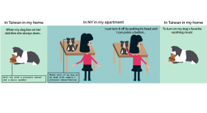
I’m creating an IoT device that recreates an interaction between my dog and I. I will create a doll model of my dog that sits on my desk (in New York). When my actual dog in Taiwan lies her head on her doll, the dog doll on my desk in NY will turn her head and follow my motion, mimicking just what she always does at home, lying beside me by the floor with her head laying on her doll animal while watching what I am doing.
in this stage of the process, I started to think of the UX part. I started by deciding to add a touchscreen to the camera. and thinking about making it work independently. but after meeting Liza, I’m reconsidering adding a button which was the initial idea. connecting both cameras through one conductive button that takes both digital and analog images.
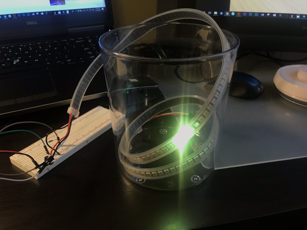
In this phase of the project, various technical approaches were considering as methods to resemble the light emitted by a firefly in a jar.
The first explored technology was a matrix of LED’s – Charlieplex-, which consisted in making a cloud of LEDs (soldering one by one) until achieving the desired lighting effect. This matrix was discarded since it requires a lot of space for wiring and hardware (hard-points), besides it is complex to test-build in the desired final object.
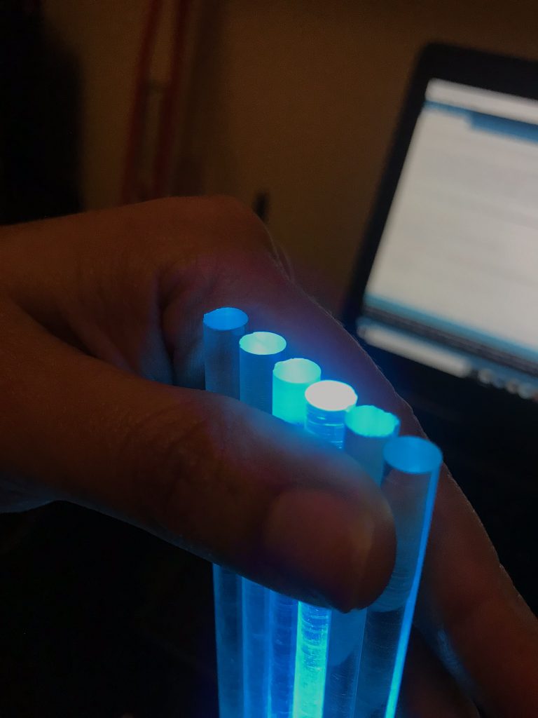
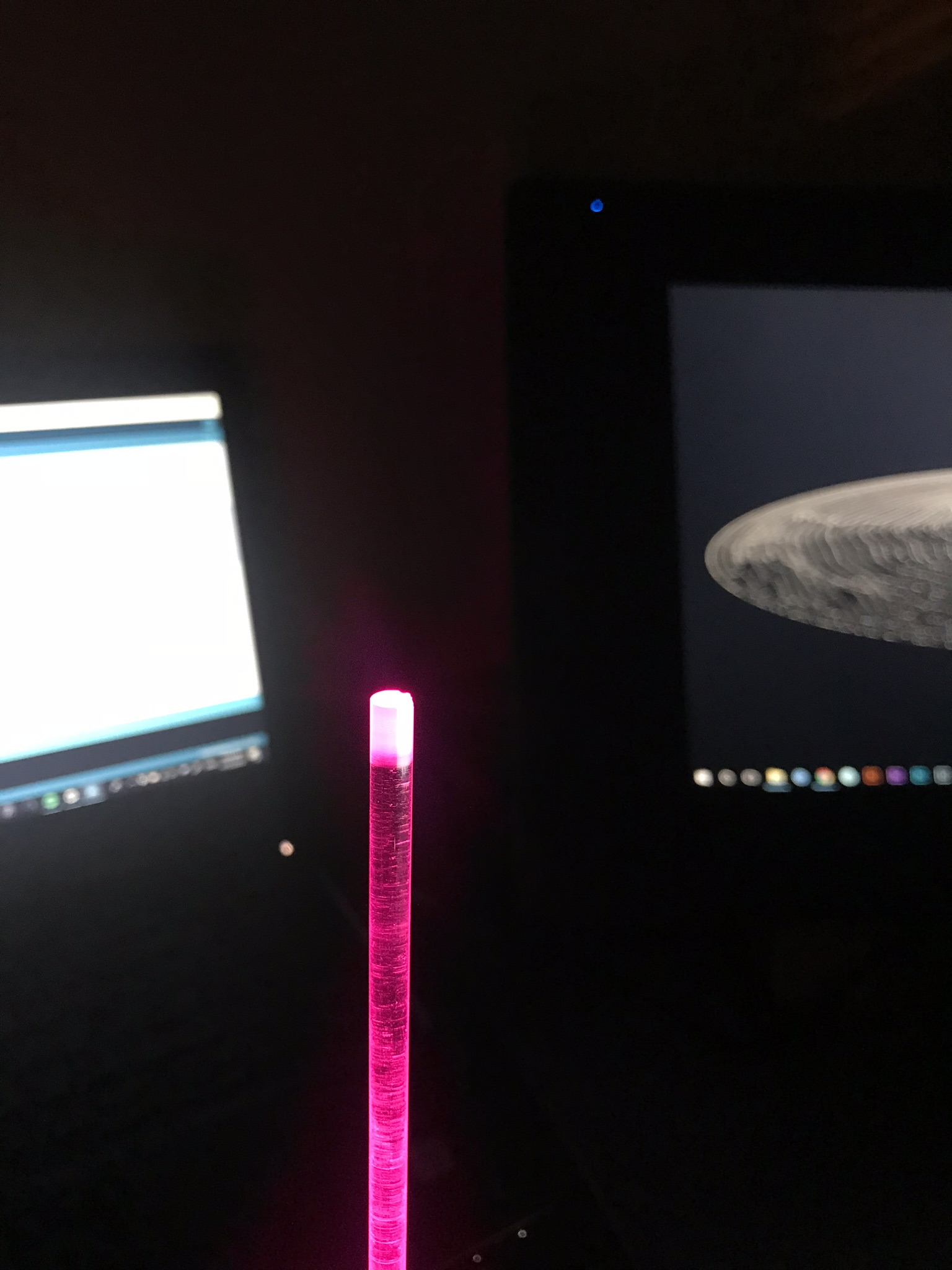
Fiber optic was another technology tested to make the effect of fireflies flying in a jar. This was not a good direction since the intensity of the light was not enough and it also required a matrix of complex LEDs on the base of the object. This image shows an exploration using acrylic rods sandblasted on the tips, to work as a fiber optic. A series of LED transmit light from the bottom of the rod.
Lasers, projectors and a mechanical system were other alternatives that were evaluated, but finally the programmable LED’s strip get the desired effect with the variations of speed and tonality of the light. In this option there is an important challenge, since the programmable LEDs require a lot of current, so a very large battery pack is needed, and this must be assembled inside the artifact without breaking its form and optimal operation. One of the requirements is to avoid using cables and power supply connected to a wall, since this would drastically affect the experience.
List of Components:
x1 Arduino Uno
x1 Breadboard
x1 Adafruit Neopixel 144 RGB LED Strip
x1 330kohm Resistor
Jumper Wires
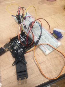
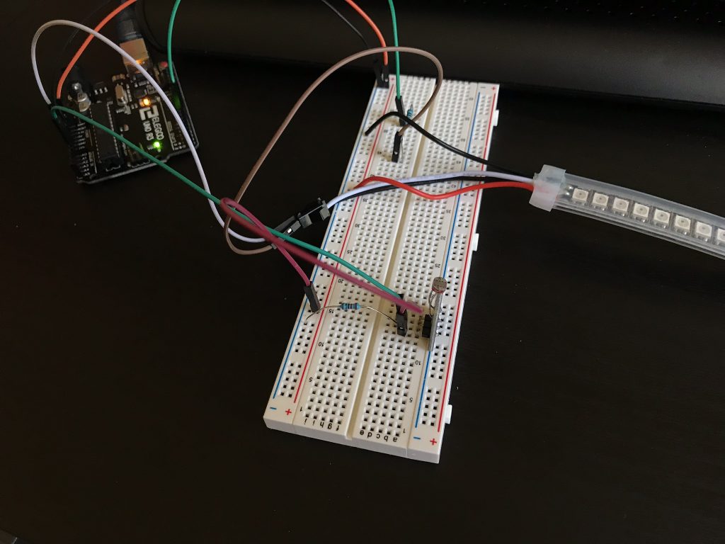
Assembly Process:
To create this prototype, I connected the Strip to the 5V of the Arduino and to the digital pin 6. Since I was planning to turn on 6 LEDs and not the whole strip, I was OK with the current provided by the computer (in this case). For the final product, I must consider the number of LEDs that are going to be on and the amount of current needed. If I would like to use all the LEDs in full white brightness, I would need around 9A to hold the whole strip. Each LED runs with around 60mA.
User Testing:
The objectives in this phase are raised from the observation of children and adults catching fireflies supported in a ‘playful’ context, and different ways in which they caught fireflies should be analyzed. The other important objective is to understand how users interact with an artifact that has no instructions, is it intuitive to use? is it too complex? why?.
In summary, in the process of catching fireflies can be identified 3 different paths.
Using the hands: Although it takes many attempts, this is a common way to catch fireflies, since it is relatively easy to catch them. For the specific development of the project, this method of catching fireflies is not the most appropriate, since an external artifact (sensor) is required and together with this a complex system that affects the simple and intuitive nature of the experience.
Using a net: Like the previous one, this is a very common and simple way to catch fireflies. This method would consist of two systems (a net -to catch- and a container -to keep the fireflies-) complex both technically and objectively, since simultaneous work is required for the experience.
Using a container: In this method the net method is basically used as the previous one, where the fireflies are trapped directly with the container so as not to let them escape. This way of catching fireflies is what most resembles the product you want to finally reach; because it is an experience with the product as such (the product is experience). It is a way that finally does not add complexity to the final product because it has no external systems, and also intuitively communicates the objective of the product in its entirety. It is important to clarify that, like any product, instructions are required, which in this particular case, was developed in the form of a story book as a sub-artifact inspired by nostalgia and memory.
After brainstorming this past week, I decided to explore my second idea in greater detail. I am excited by the prospect of using art and poetry as dynamic tools of resistance to counter biases and protest against skewed power structures.
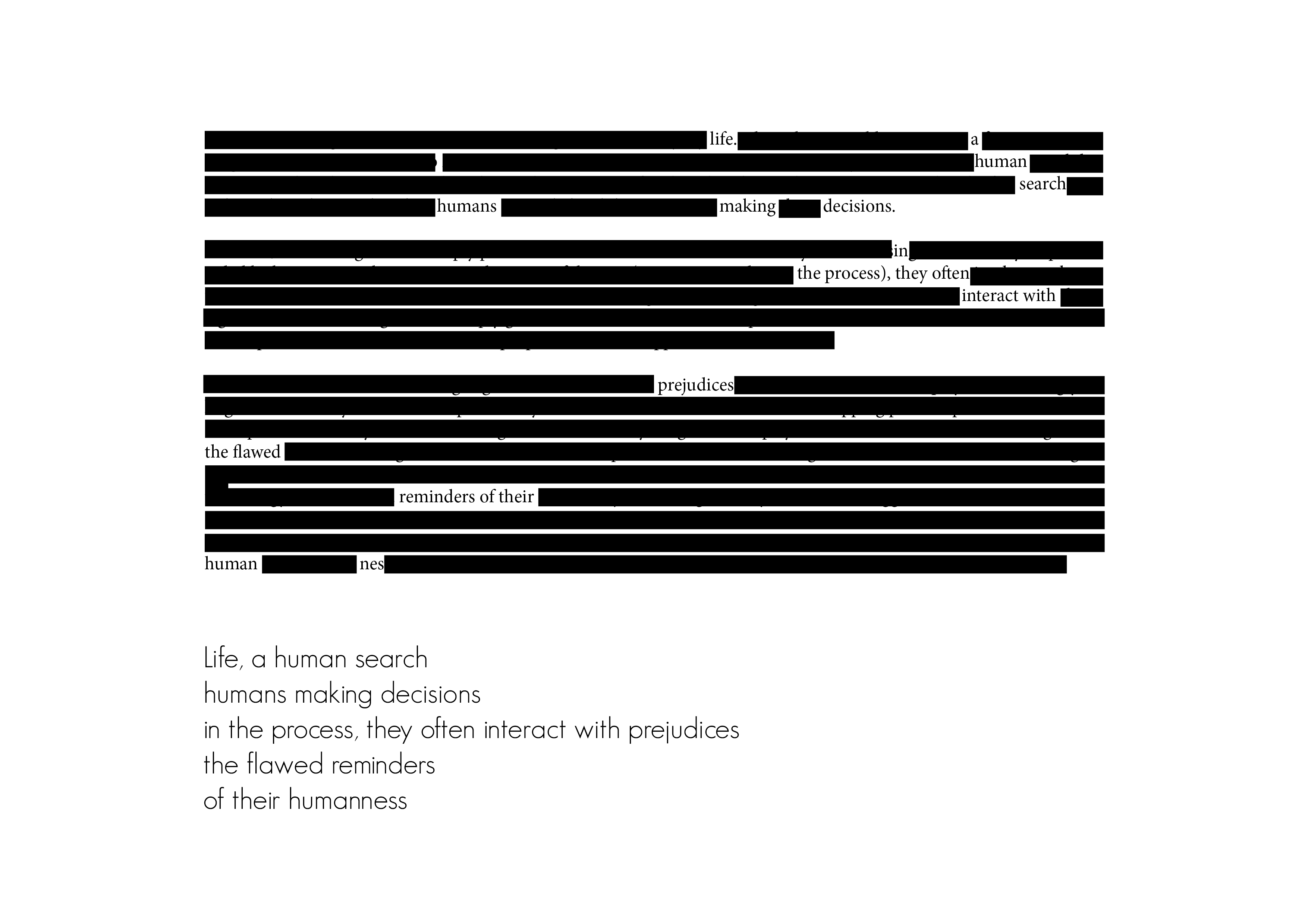
I want to create a blackout poetry generator- which on being “fed” text can create hopeful, optimistic poetry. Blackout poetry is a genre of poetry, where removing pieces of narrative helps craft a new story.
Using a tech crunch article about bias in algorithms
Using a 1973 advertisement by Donald Trump, advocating the death penalty
Systems flow
Ideally, I would like to create a program that could computationally generate meaningful poetry from the snippets of text it is provided. I was imagining a setup, where the input could be either analog (piece of paper) or digital(article), the text would be analyzed and blackout poetry generated. The challenge is then to make something that is not only grammatically but syntactically correct too.
Prototype
For this prototype, I decided to experiment with thermochromic pigment, which has heat sensitive compounds that change color upon reaching a certain temperature. I was working with black thermochromic pigment, which on being heated becomes clear. I tried using it with two types of glue and paint to see what would work the best. After applying the mixture to paper, I tried creating a circuit using Copper tape to heat certain portions of the text. I am unable to reach the appropriate temperature that would activate the color change.
Challenges and future iterations
Midway through the exercise, I realized that I want the color to change from clear to black and not the other way round. I wonder if a better alternative would be to use cooling pads instead?
Also, I wonder if there are alternatives to using thermochromic ink- could there be a motorized system instead- which on receiving the input (the hate speech, for example), dispenses/ outputs the blackout poetry?
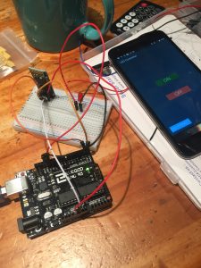
Goal of the project and/or desired interaction This week our homework was to choose one of the wireless topics covered in class and put it to practice for use in everyday life. I choose Bluetooth because it would be really cool to be able to communicate wireless to turn on a sensor. I decided to use Bluetooth to connect to an android phone to turn on and off an LED.
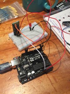
Quick description of assembly and list of core components 1x Arduino
1x Medium breadboard.1x Red LED 1x HC 05/06 Bluetooth Module 1x Resistors (220 ohms) Jump wires
Andriod Phone
How it works The connection is simple. Only four connections to be made between Arduino and Bluetooth. After that, just connect your LED to pin 13 on one side and connect it to a 220ohms resistor.
Arduino Pins Bluetooth Pins
RX (Pin 0) ———> TX
TX (Pin 1) ———> RX
5V ———> VCC
GND ———> GND
After connecting all the wires and led, with the Bluetooth module in place, you then download an APP on the android to connect to the Bluetooth module. Then by using the LED app, you can simply turn on and off a LED with a click on the screen.
Any problems you encountered and/or solved At first, I cannot connect to the Bluetooth for the longest time. I realized the trick is not to connect the RX and TX of the Arduino pins to the TX and RX Bluetooth pins when you upload the sketch. After uploading the code and then connect these, the Bluetooth will connect fine.
At this time, there are mainly two ideas that I am thinking about. This past semester, I have been intrigued by the interaction between man and machine- the areas of overlap, the process of co-creation, almost-collaboration that has become commonplace as traditional processes become automated. This area of inquiry is very nuanced and layered- which makes it difficult to categorize it into the binaries of good/ bad or right/ wrong. I am imagining an exhibit, with two different sections- one about machines and humans creating generative art together. The second would be about machines re-inforcing human bias.
The second idea revolves around poetry and power. I want to infuse optimism in instances which show the very worst of human existence- by changing the context of the narrative. I envision a space, with a series of artifacts that explore this theme.
Timeline
Week 11: April 2nd – April 8th
Research, brainstorm, ideate and keep refining the concept statement. Define the audience and context of use. Look at relevant precedents and work that inspires me. Experiment with different ways of inputting information.
Week 12: April 9th – April 15th
Finalize project form. Prototype the technical build of the project and simultaneously start thinking about the look and feel.
Week 13: April 16th – April 22nd
Start assembling/ working on the smaller circuitry that will be a part of the larger project. At the same time, start building/ working on the final fabrication.
Week 14: April 23rd – April 29th
Keep working on the final project. Start preparing the presentation (research + precedents + concept + project documentation).
Week 15: April 30th – May 6
Work on the final presentation. Refine the project by maybe having supplemental material?
The Form
The form is still nebulous and I am undecided about what would be the most effective expression of my concept.
Prototype 1
My idea is still in the conceptualization stages. For the first prototype, I was experimenting with some tools and sensors that I have always been curious about but have never got an opportunity to integrate into my work.
Trial 1
I am intrigued by the idea of being able to draw with the Arduino- especially using different/ unusual input methods. I am also curious about whether the same “sketch” can be modified by two different individuals, interacting with separate systems. To begin with, I tried connecting the Arduino to p5.js, a javascript library that is useful for creating graphics and interactive experiences. The breadboard setup was simple- a 10K potentiometer, with one leg to the 5V power supply, the second to Analog input pin A1, and the third to the ground of the breadboard. I mapped the analog readings of the potentiometer from a range of 0 to 1023 to 0 to 255 and then printed the values on the serial monitor.
The web server cannot communicate with the serial port directly. There is an application called p5.serialcontrol that helps serve this function. One can control the ports using the app. There is also a Javascript file with relevant event and callback functions that need to be included in the p5 file to get it to work.
What I did get working: I was able to connect the Arduino to p5.js, using a locally run web server
What is not working: The readings are very erroneous, and unstable- they keep fluctuating
Next steps: Potentially connect two different laptops and work on the same visual output using multiple sensors ( potentiometer + light sensor)
Trial 2
Using the temperature and humidity sensor: Again, the wiring is very basic but I am having troubles with installing and using the library. Will keep working on this. I don’t know whether this is the right sensor for trying to detect someone blowing air/ changes in the immediate environment because of hand gestures/ body movement.
Trial 3
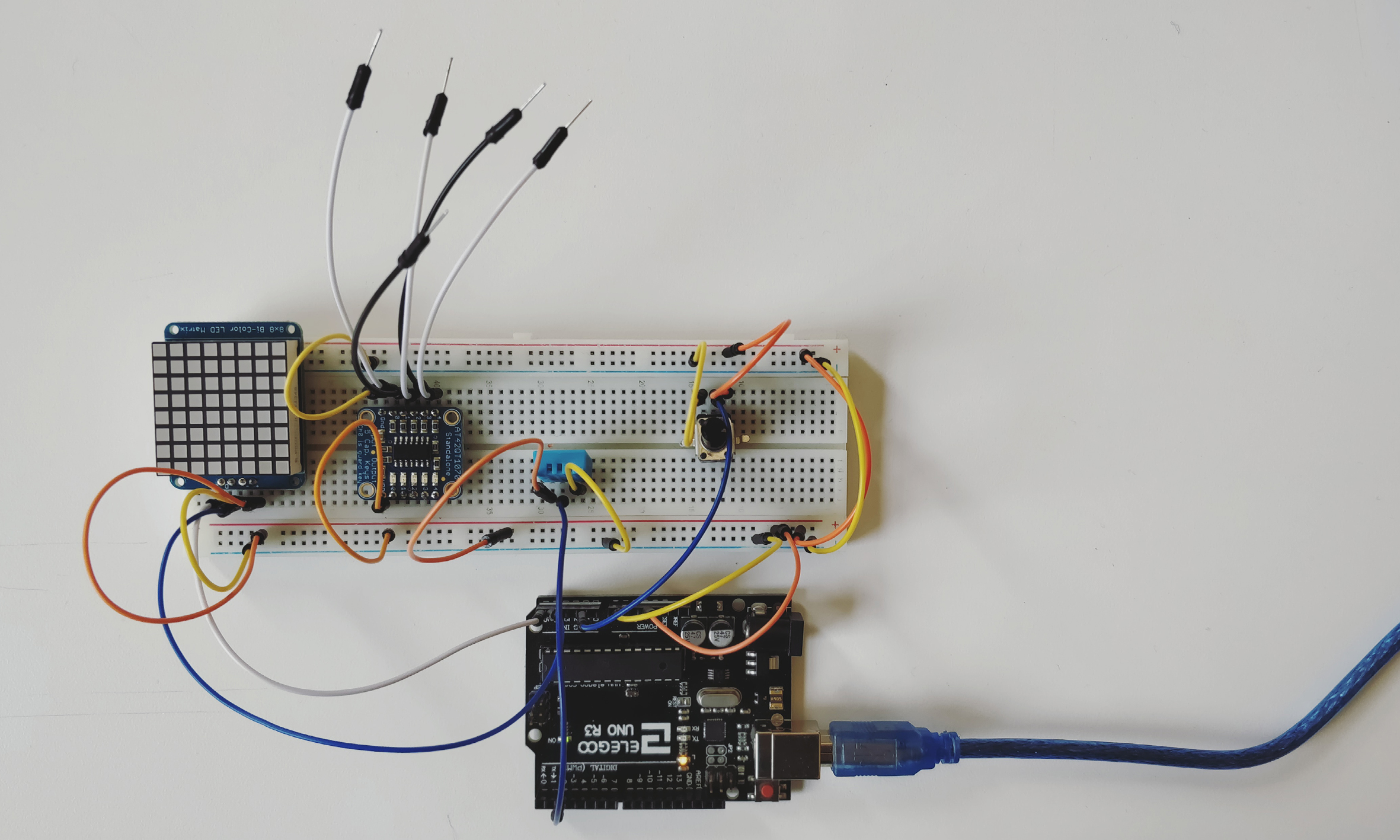
Using the standalone 5- pad capacitive touch sensor breakout. This particular component is really interesting. It does not need to be operated via a micro-controller and functions well by itself. The wiring is really simple- the details of which are available on https://www.adafruit.com/product/1362. After having worked on capacitive sensing a few weeks back, I was surprised at the sensitivity and level of precision this board provided.
Next steps: I want to connect the board to other outputs- like motors/ LED’s to see how it will work
Trial 4
Another component that I have had for a long time but never had a chance to use is the 8*8 Bicolor LED matrix. The wiring is standard and is included on the site. The matrix can be programmed to show different graphical outputs.
Next steps and questions: Could a programme translate a drawing that the user makes into coordinates that could be displayed on a matrix? Can multiple matrices display different portions of the same “sketch”?
While taking the video, I realized that taking a close up of the LEDs gives very interesting visual results.
The intention with this prototype is to quickly visualize the idea and the concept, and to test the interest and reaction of the audience to this experience.
The prototype is screen based, made from a 120 series of “photoshoped” images where is possible to see the behavior and response of the hardware and experience with the inputs of the user.