LED CONTROL VIA BUTTON
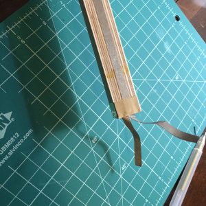
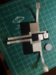
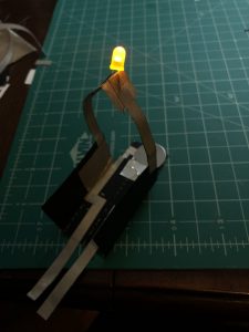
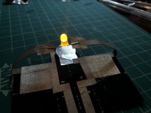
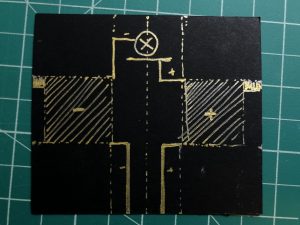
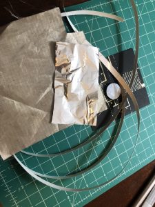
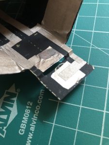
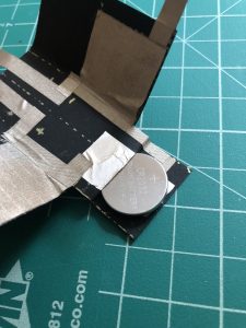
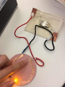
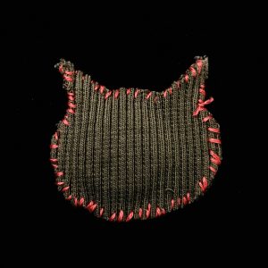
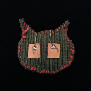
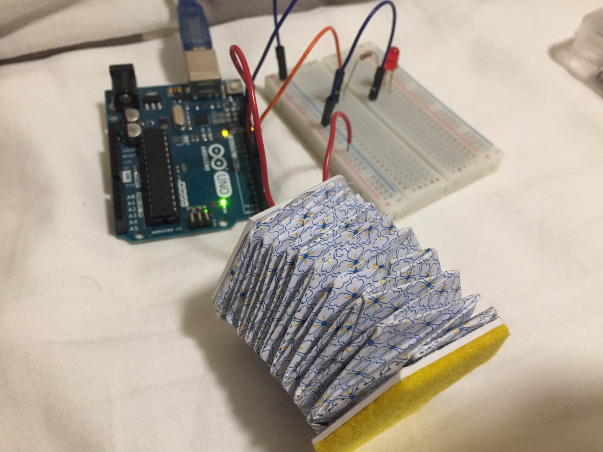
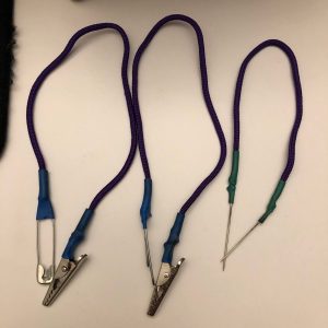
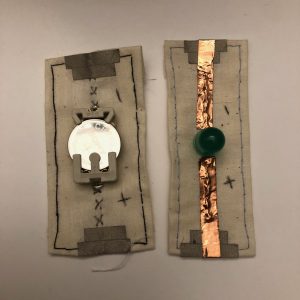
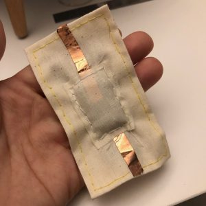
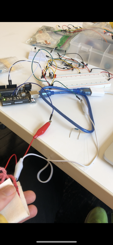
Thanks to Dario for the soft switch. It works perfectly fine. I like how squishy of the switch. The circuit is pretty simple. I use “INPUT_PULLUP” for the switch. It’s a quick tip for all buttons 😀
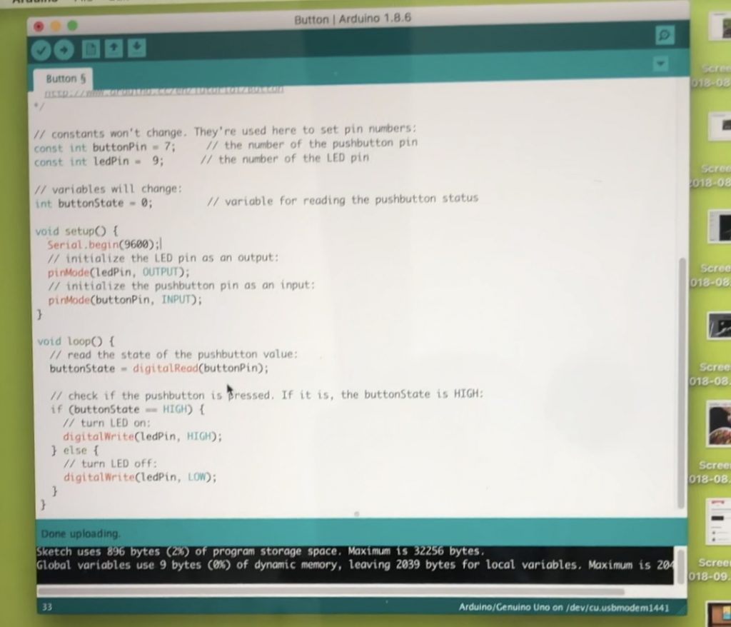
LED CONTROL VIA BUTTON CODE
/*
Button
The circuit:
– LED attached from pin 13 to ground
– pushbutton attached to pin 2 from +5V
– 10K resistor attached to pin 2 from ground
– Note: on most Arduinos there is already an LED on the board
attached to pin 13.
created 2005
by DojoDave <http://www.0j0.org>
modified 30 Aug 2011
by Tom Igoe
This example code is in the public domain.
http://www.arduino.cc/en/Tutorial/Button
*/
// constants won’t change. They’re used here to set pin numbers:
const int buttonPin = 8; // the number of the pushbutton pin
const int ledPin = 7; // the number of the LED pin
// variables will change:
int buttonState = 0; // variable for reading the pushbutton status
void setup() {
// initialize the LED pin as an output:
pinMode(ledPin, OUTPUT);
// initialize the pushbutton pin as an input:
pinMode(buttonPin, INPUT_PULLUP);
}
void loop() {
// read the state of the pushbutton value:
buttonState = digitalRead(buttonPin);
// check if the pushbutton is pressed. If it is, the buttonState is HIGH:
if (buttonState == HIGH) {
// turn LED on:
digitalWrite(ledPin, LOW);
} else {
// turn LED off:
digitalWrite(ledPin, HIGH);
}
}
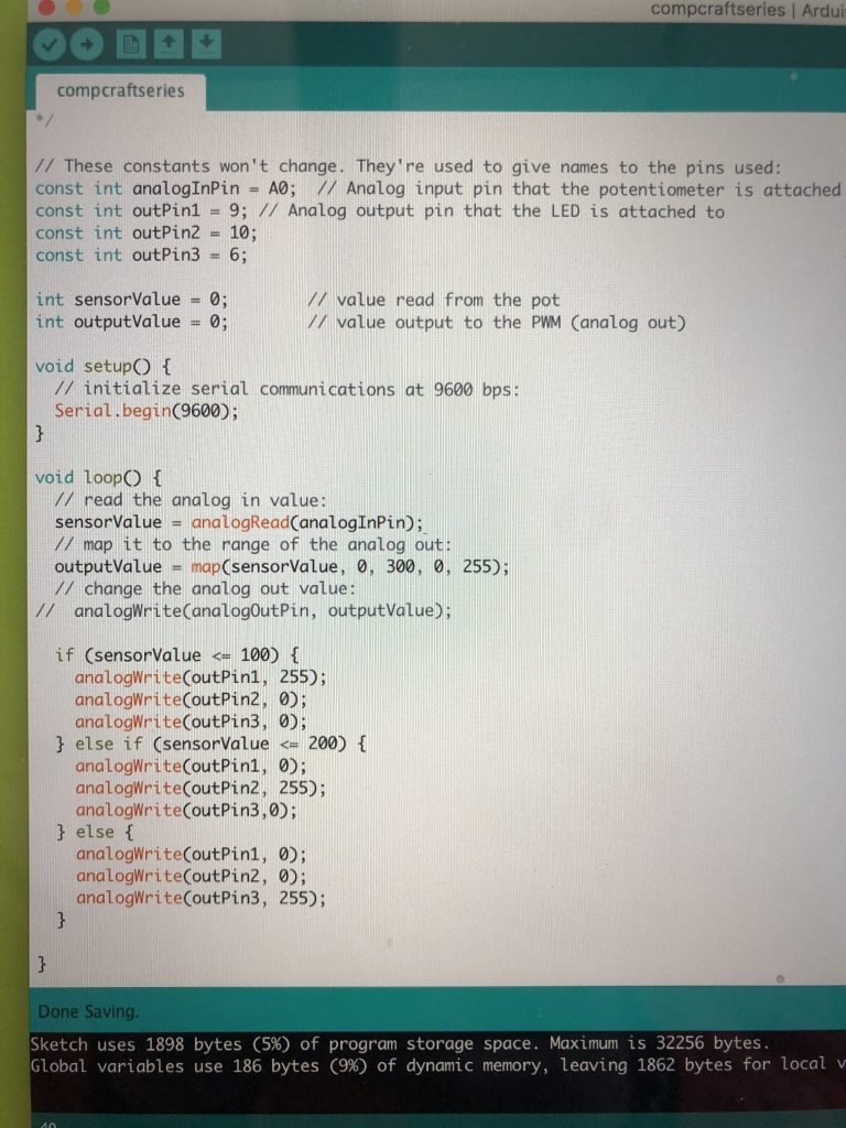
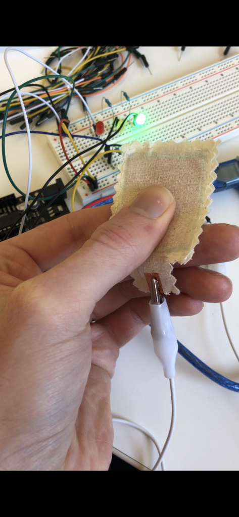
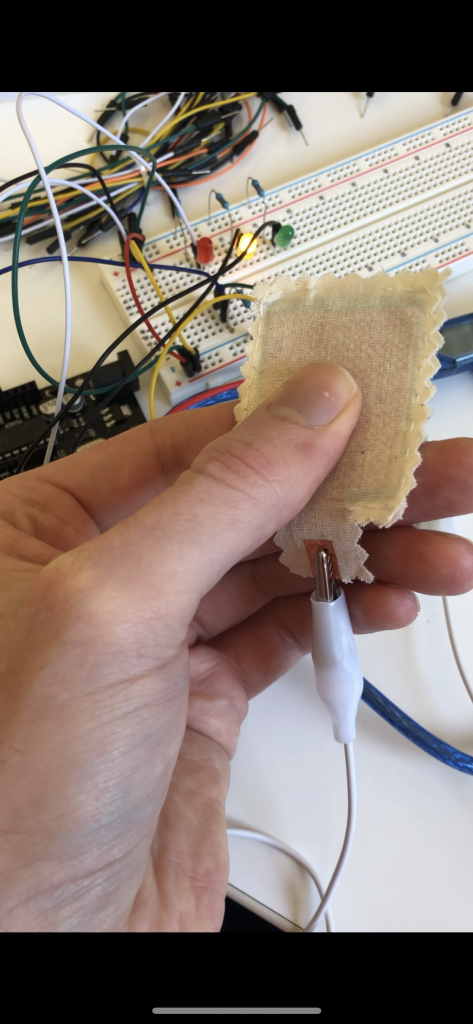
MARCH OF LEDs
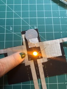
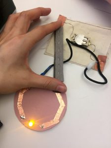
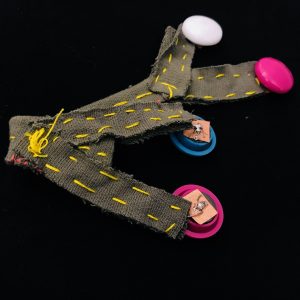
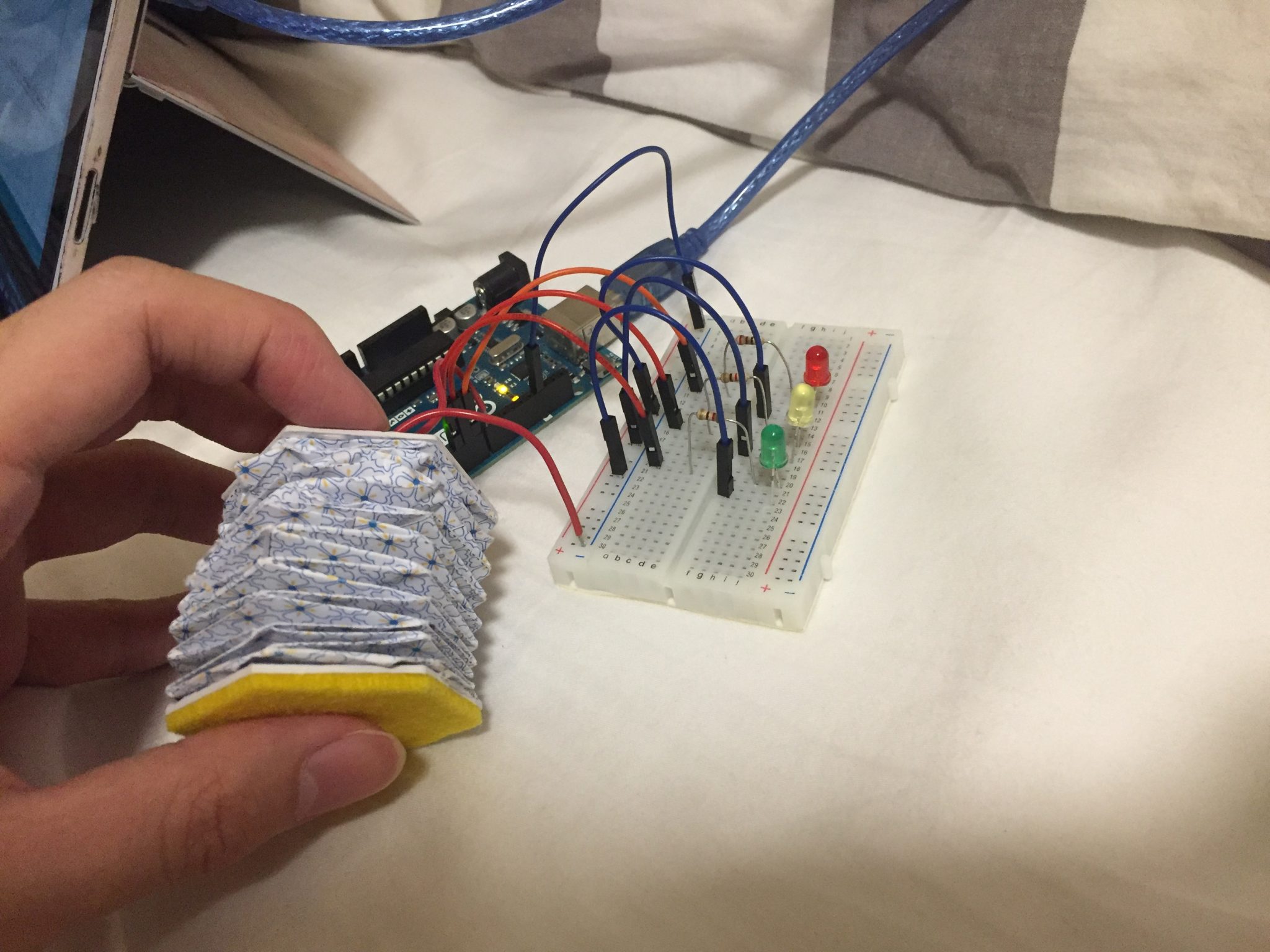
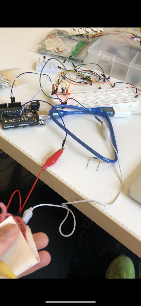
It is tricky to make each of them light up when I press my switch. I have to make the specific states for them to light up in order. It’s pretty fun and cute with 3 LEDs with Red, Yellow and Green.
MARCH OF LEDs CODE
/*
Button
Turns on and off a light emitting diode(LED) connected to digital pin 13,
when pressing a pushbutton attached to pin 2.
The circuit:
– LED attached from pin 13 to ground
– pushbutton attached to pin 2 from +5V
– 10K resistor attached to pin 2 from ground
– Note: on most Arduinos there is already an LED on the board
attached to pin 13.
created 2005
by DojoDave <http://www.0j0.org>
modified 30 Aug 2011
by Tom Igoe
This example code is in the public domain.
http://www.arduino.cc/en/Tutorial/Button
*/
// constants won’t change. They’re used here to set pin numbers:
const int buttonPin = 8; // the number of the pushbutton pin
const int ledPin = 7; // the number of the LED pin
bool startCapture;
float Timer = 0;
float Duration = 10000;
int State = 0;
bool Pressed;
bool Added;
// variables will change:
int buttonState = 0; // variable for reading the pushbutton status
void setup() {
Serial.begin(9600);
// initialize the LED pin as an output:
pinMode(ledPin, OUTPUT);
pinMode(6, OUTPUT);
pinMode(5, OUTPUT);
// initialize the pushbutton pin as an input:
pinMode(buttonPin, INPUT_PULLUP);
}
void loop() {
// read the state of the pushbutton value:
buttonState = digitalRead(buttonPin);
Serial.println(State);
if (!Pressed && buttonState == 0)
{
Pressed = true;
}
if (Pressed && buttonState == 1)
{
Pressed = false;
Added = false;
}
if (Pressed && !Added)
{
State++;
Added = true;
}
if (State == 1)
{
digitalWrite(7, HIGH);
digitalWrite(6, LOW);
digitalWrite(5, LOW);
}
if (State == 2)
{
digitalWrite(7, HIGH);
digitalWrite(6, HIGH);
}
if (State == 3)
{
digitalWrite(7, HIGH);
digitalWrite(6, HIGH);
digitalWrite(5, HIGH);
}
if (State > 3)
{
digitalWrite(7, LOW);
digitalWrite(6, LOW);
digitalWrite(5, LOW);
State = 0;
}
}
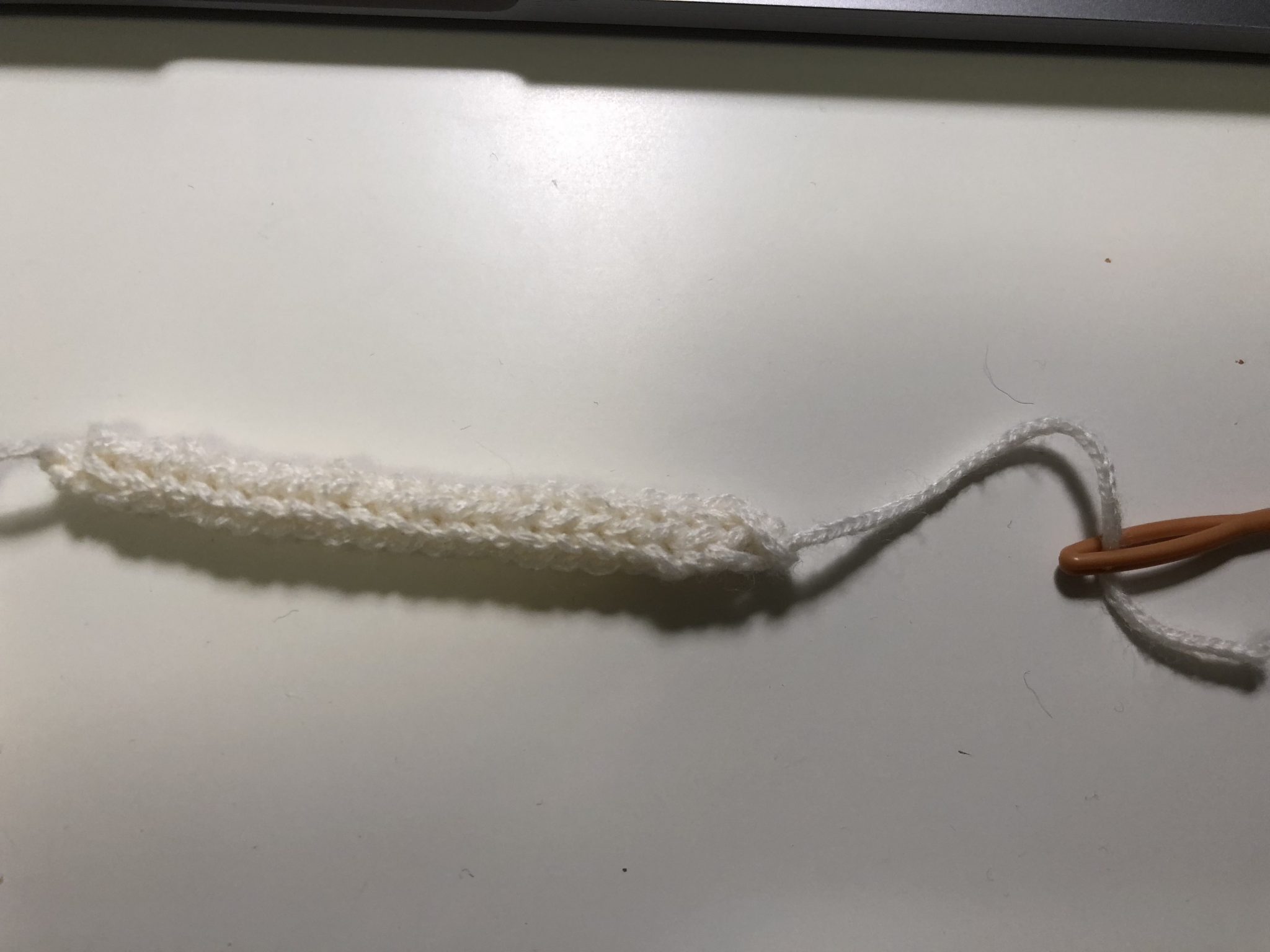
MIDTERM IDEA
I want to make one big squishy doll that can emit some lights through its eyes by dragging the tail. It could be really cute! The technique I use is going to be wool felting.

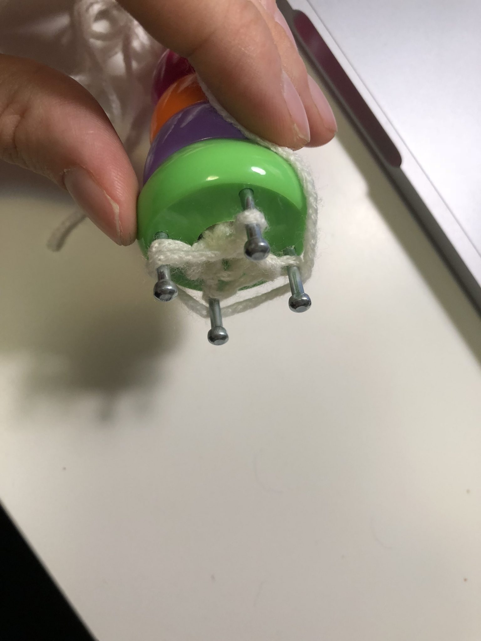

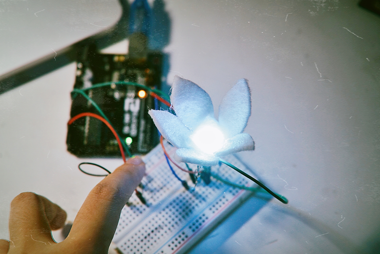


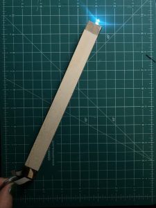
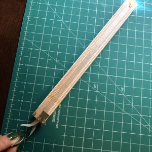
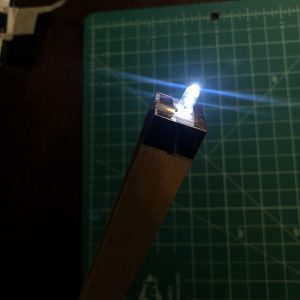
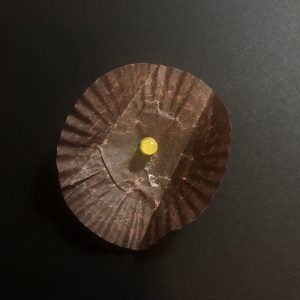
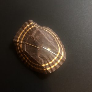
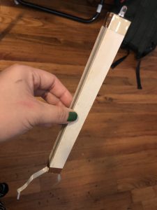 My “candle” ?