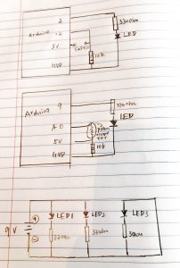
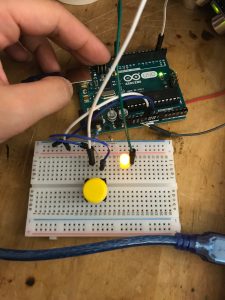
This week is the flashlight assignment which I start from connecting several LEDs with 9v battery and resistors. Then tried to use button and potentiometer to turn on and off of led lights. Attached are circuits and photo for these explorations.
This week is the flashlight assignment which I start from connecting several LEDs with 9v battery and resistors. Then tried to use button and potentiometer to turn on and off of led lights. Attached are circuits and photo for these explorations.
Fish on Wheels is a very interesting Pcomp project invented by Dutch design collective Studio Diip. They added wheels and sensors to a fish tank so that its inhabitant can drive it by swimming in a certain direction. The tank itself was controlled by Arduino, and the main method used to detect fish’s movement is computer vision, with the camera on the top of the tank.
How it works – As the fish swims around the transparent tank, a webcam positioned above the water tracks its movements – detecting the contrast between the fish and the bottom of the tank – and relays them to the Arduino. Using programming to mimic the fish’s movements by driving the vehicle in the same direction.
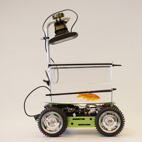
Image source and related article from Dezeen
I like this project because there is a goodwill behind it – “Our pet fish have always been limited to their water holding area known as ‘the fish tank’,” said Studio Diip, “In an attempt to liberate fish all over the world, the first self-driving car for fish has been developed.” Overall, the method used in this project is really simple but the outcome is humorous and inspiring.
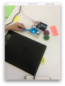
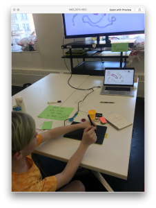
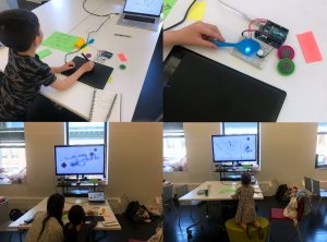
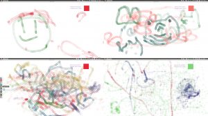
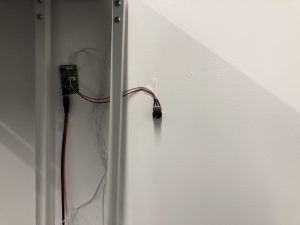
This project has three parts, color sensor, Wacom digitizer, digital screen. This installation will set up on the darkroom for the better user experience, when a user comes into the room they can find some objects placed around the color sensor, they may try them at first them find the other color they need in the surrounding.
Prototype:
Playtesting:
I attended the PLAYTECH (in D12) activity for the children and teenagers user testing, I use my conceptual prototype to test more than ten young people at a total. The main part I test is the stability of the sensor, the playability of the function, the unexpected outcomes from a different kid.
I provide the RGB sensor which can catch the color you input form the objects with a tip note, also I put a Wacom board and digital pen beside the sensor to test how they react with them.
Process:
Outcome:
Feedback:
Iteration:
DC motors
DC motor is a continuous rotation motors, it only has two wires. This motor will work when you give it the power no matter what, and it will stop when you remove the power.
Servo Motors
The position of servo motors can be controlled more precisely than those of standard DC motors, and they usually have three wires (power, ground & control).Power to servo motors is constantly applied, with the servo control circuit regulating the draw to drive the motor. Servo motors are designed for more specific tasks where position needs to be defined accurately.
Stepper Motors
A stepper motor is essentially a servo motor that uses a different method of motorisation. Where a servo motor uses a continuous rotation DC motor and integrated controller circuit, stepper motors utilise multiple toothed electromagnets arranged around a central gear to define position.
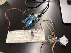
design goal:
I use the potentiometer to control the servo motor rotates, when you give more power to the servo motor, the motor with move faster. I think it can use in the children electronic toy, as a parent, they can control the toy move or stop.
Materials:
-Arduino + USB Cable
-Potentiometer
-Servo Motor
-Breadboard
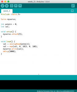
Code:
Demo:
For this week’s assignment, I use the sound sensor to control the LEDs depends on the different levels of the sound inputted.
List of Materials
1 x Elegoo Uno R3
1 x Full sized breadboard
1 x sound sensor
3 x LEDs
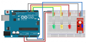
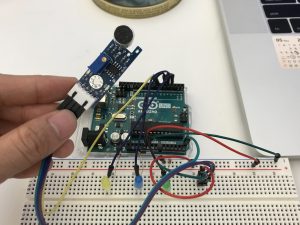
How it works:
three LEDs will blink when the sound’s value changed, but I noticed that the sound sensor is not that sensitive to detect the accurate sound.
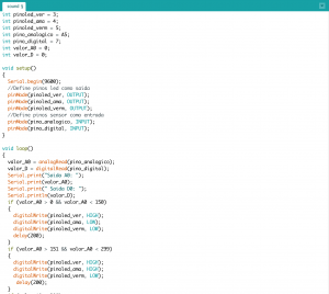
code:

video:

Presentation: https://docs.google.com/presentation/d/1sUYrrKJgouIBgrMRpbiFp6CLde5otBWy1A05Q2PdyU4/edit?usp=sharing
Concept + Goals. What is your concept? What were your goals? Why did you decide on this project form for your concept and goal?
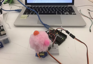
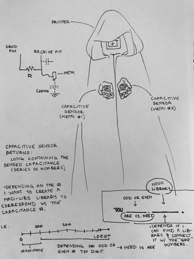
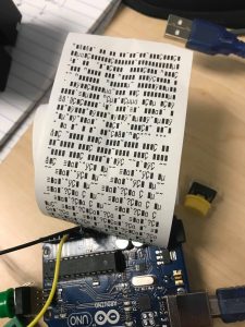
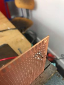
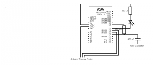
The Fortune Teller: Using an arduino, arduino printer, and a copper capacitive sensor I want to be able to give people a fortune based on the “random” amount of particles the sensor reads. Inspired by Mary Poppins measurement tape that collects the input of height and gives a corresponding description, “Perfect in everyway” and Zoltar, I want to design a fortune teller that reads its participants touch and subsequently gives them a corresponding fortune.
Intended audience. Who is this for? Why did you choose this audience?
Given that my idea of a fortune teller utilizes a non-invasive sensor my intended audience is anyone who is conveniently available and interested in getting a fortune.
Precedents. Share any precedents that inspired you.
Since one of the main components, if not the, of my project is to be able “sense” some aspect of my participant(s) I needed a sensor that could do just that in a relatively quantifiable way. I considered using a TMP36 Temperature Sensor so when a participant would get near/ touch the fortune teller depending on the temperature the fortune would change. Upon further deliberation, I believe most people range within the same body temperature so I wanted to use a component that could sense something with more range. Tubah (a tutor) recommended a capacitive sensor.
The capacitor is a component which has the ability or “capacity” to store energy in the form of an electrical charge producing a potential difference (Static Voltage) across its plates, much like a small rechargeable battery. Capacity is very sensitive and can be affected from a variety of environmental factors making it’s output very inconsistent. Accordingly, using this aspect to my advantage when touched all individuals can produce a unique capacitance… therefore fortune.
Description of the project. Discuss the process of creating this project. How does it work? What is the desired interaction?
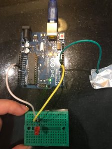
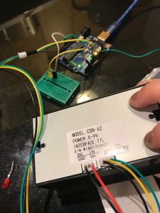
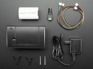
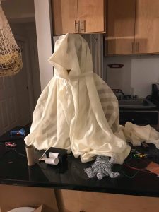
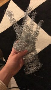
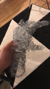
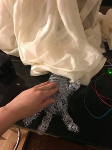
This project is simple in its composition. It utilizes a single sensor, capacitive, and a single mode of output, a printer. I started the project with the physical components; the capacitive sensor and then the thermal printer. I found different tutorials for physical component that related to the outcome I needed. For example the capacitive code I used had a pre-set threshold of a 1000 and utilized an LED to show that the capacity was being read correctly. These details came in handy when it was no longer plugged into a monitor that could read the resistance since the LED would alert me to if the capacity was being read correctly. My next step after the physical setting up that was connecting the two through the code; have the printer respond to a capacitance that passes a threshold and have ranges equal different “fortunes.” I originally wanted to design two plaster hands that had metal wire running through them thus becoming the capacitor. With this idea, the participant would put their hands in the fortune teller’s hand, mimicking the interaction of a stereotypical gypsy fortune reading, and get their fortune. Though after the Parsons 2 building accident, which affected the wet lab, I used garden wire wrapped together as the hand instead. Ultimately, the project was successful. I made a capacitive sensor that was able to read capacity through a metal-wire-hand and subsequently read that input and print the corresponding fortune through code in the Arduino.
Process + Prototypes. Discuss the process of creating this project. Show your prototypes, playtests, sketches, interaction diagrams, and any other files that illustrate the tools you used. What challenges did you faced?


CapacitiveSensor cs_4_8 = CapacitiveSensor(4, 8); // 1M resistor between pins 4 & 8, pin 8 is sensor pin, add a wire and or foil
#include “Adafruit_Thermal.h”
#include “adalogo.h”
#include “adaqrcode.h”
int LED = 8;
int buttonpin = 3;
//FIND A 10K resistor! Check if this is still relevant.
#include “SoftwareSerial.h”
#define TX_PIN 6 // Arduino transmit YELLOW WIRE labeled RX on printer
#define RX_PIN 5 // Arduino receive GREEN WIRE labeled TX on printer
SoftwareSerial mySerial(RX_PIN, TX_PIN); // Declare SoftwareSerial obj first
Adafruit_Thermal printer(&mySerial); // Pass addr to printer constructor
// Then see setup() function regarding serial & printer begin() calls.
// Here’s the syntax for hardware serial (e.g. Arduino Due) ————–
// Un-comment the following line if using hardware serial:
//Adafruit_Thermal printer(&Serial1); // Or Serial2, Serial3, etc.
// ———————————————————————–
void setup() {
cs_4_8.set_CS_AutocaL_Millis(0xFFFFFFFF);// turn off autocalibrate on channel 1 – just as an example
pinMode(7, OUTPUT);
// pinMode(7, OUTPUT); digitalWrite(7, LOW);
// This line is for compatibility with the Adafruit IotP project pack,
// which uses pin 7 as a spare grounding point. You only need this if
// wired up the same way (w/3-pin header into pins 5/6/7):
pinMode(5, OUTPUT); digitalWrite(5, LOW);
pinMode (buttonpin, INPUT);
// cs_4_8.set_CS_AutocaL_Millis(0xFFFFFFFF);// turn off autocalibrate on channel 1 – just as an example
// Serial.begin(9600);
// pinMode(7, OUTPUT);
// NOTE: SOME PRINTERS NEED 9600 BAUD instead of 19200, check test page.
pinMode(LED, OUTPUT); digitalWrite(LED, LOW);
Serial.begin(9600);
mySerial.begin(19200); // Initialize SoftwareSerial
//Serial1.begin(9600); // Use this instead if using hardware serial
printer.begin(); // Init printer (same regardless of serial type)
}
void box(char *string) {
uint8_t i, len = strlen(string);
//printer.write(0xDA);//upper-left corner
for (i = 0; i < len; i++)printer.write(0xC4);// Top Edge
// printer.write(0xBF);// Upper-right corner
printer.setSize(‘S’); //Size
//printer.println();//NewLine/Feed
//printer.write(0xB3); //left edge
printer.print(string);
//printer.println(sensor1); How to print the capacity ?
//printer.println(0xB3);
// printer.println(0xB3);
//printer.println();//Newline/Feed
// printer.write(0xC0); //Lower-Left corner
for (i = 0; i < len; i++) printer.write(0xC4);//Bottom Edge
//printer.write(0xD9); //Lower-right Corner
printer.println();//NewLine/Feed
}
void loop() {
long sensor1 = cs_4_8.capacitiveSensor(50);
Serial.println(sensor1); // print sensor output
//if(4999 % 3 == 0)
if (sensor1 >= 4000) {
digitalWrite(7, HIGH);
delay(100);
digitalWrite(7, LOW);
if (sensor1 % 2 == 0) {
// printer.println(F(“The world is your oyster+”));
box(“The World is Your Oyster+”);
} else {
box(“You Are Special-“);
}
printer.println(F(“”));
printer.println(F(“”));
printer.println(F(“”));
printer.feed(2);
printer.sleep(); // Tell printer to sleep
delay(3000); // Sleep for 3 seconds
printer.wake(); // MUST wake() before printing again, even if reset
printer.setDefault(); // Restore printer to defaults
} else if (sensor1 >= 2950) {
digitalWrite(7, HIGH);
delay(100);
digitalWrite(7, LOW);
if (sensor1 % 2 == 0) {
box(“Have Empathy+”);
} else {
box(“Don’t Be Too Manipulated By Emotions-“);
}
printer.println(F(“”));
printer.println(F(“”));
printer.println(F(“”));
printer.feed(2);
printer.sleep(); // Tell printer to sleep
delay(3000); // Sleep for 3 seconds
printer.wake(); // MUST wake() before printing again, even if reset
printer.setDefault(); // Restore printer to defaults
Design Statement
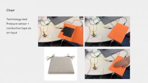
We are making a series of experimental prototypes that explore the ubiquitous but novel relationship between humans and objects. By reimagining the messages behind everyday objects, the project enables everyday objects to communicate and negotiate with us in their (possibly) preferable way.
Prototypes
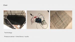
1#Chair
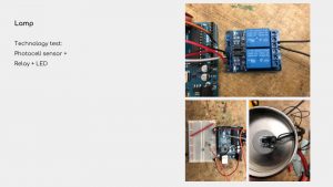
2#Lamp
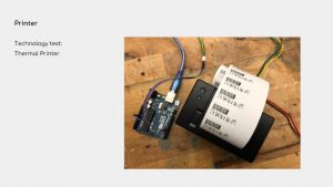
3#Printer
PART 1
DC motor: Continuous rotation, very fast.
Servo motor: Turn 90° in either direction for a total of 180° movement. Have a position sensor inside for feedback.
Stepper motor: Precise positional control, move 1 step each time. No position sensor for feedback.
PART 2
Example#1
A DC Motor fan which works for a while and rest for a while. I think it can be used for cooling down the computer when it operates tasks which generate lots of heat.
Example#2
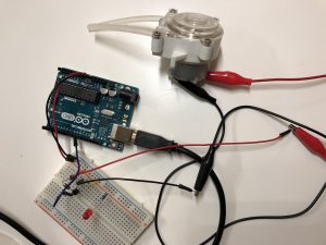
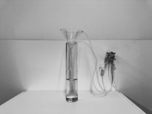
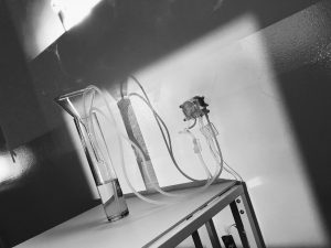
A water pump made with a 6V DC Motor. I made a installation out of it. One side of the pump is up-taking water and the other is dropping the water in the same container. I used 4 AA battery as external power for the water pump and a potentiometer to adjust the speed of the water pump.
This is hands-down the BEST tutorial I have come across to describe how a transistor works and why it can act as a switch and signal amplifier. For those of you who are working with loads that need more current/voltage and therefore a transistor, I *highly* recommend you watch this immediately.
Enjoy 🙂
DC Motor:
Two wire (power & ground), continuous rotation motors
Using pulse width modulation (PWM) to control the speed of DC
Stepper Motor:
Use multiple electromagnets around gear to divide a full rotation into equal steps.
Requires extra controller.
Servo Motor: Generally assembled by a DC motor, a gearing set, a control circuit and a position-sensor (so position can be controller precisely).
Usually three wires (power, ground, signal)
Using pulse width modulation (PWM) to control the signals of servomotors.
Use knob to control the speed of a stepper motor.
Core components
1* potentiometer
1* step motor
Wires & jumpwires
Arduino board
How it works
Use knob to control the speed of a stepper motor.
Problems
Can’t see the movement of stepper, though I can feel it changes.