I’m here,
I’m here,
Are you there?
Adrift – Final project – Liliana Farber
Leave a reply
I’m here,
I’m here,
Are you there?
This is my final blog post including all deliverables required:
1.Final presentation
https://drive.google.com/file/d/1B-UEswSAtg4PgTHOUH33RxvD7tlx0vFU/view?usp=sharing
2. My final documentation below.
The Issuu document covers: Concept + Goals, Intended audience, Precedents, Description of the project, Materials list, Process + Prototypes, Circuit diagram + Code, Challenges, and Conclusion. In addition, I have included part of my research too because it’s important to understand the nature of my project.
3. Video documentation


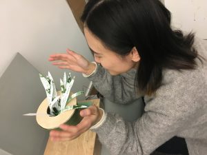
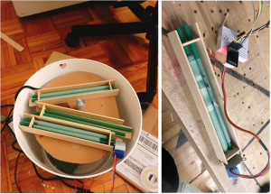
This week I focused on the best way of simulating the plant growing effect. I did a lot of experiment on motors. I first used the linear motor but it doesn’t quite do the job well. Then I decided to use some stepper motors to control some brunch of the leaves. But what I need to figure out later is how I can fit so many stepper motors in that flower pot.

Context
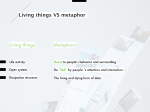
Data has never been as valuable in human history as it is today. As data is becoming an essential part of our society, it is crucial to discuss that what the relationship between data and people is right now and the possible form of information is going to develop.
So what if the online information had a lifespan of living things in reality? Would people see or treat information in another way? I am planning to do research on social media information and how users interact with the information they receive and send in their daily lives to discover the possibility of reversing people’s negative attitude towards information.
Concept statement
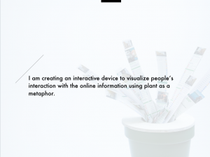
I am creating an interactive device to visualize people’s interaction with the online information using the plant as a metaphor. Through interacting with the installation, people can understand how our interaction can influence data and rethink or imagine our possible relationship with data.

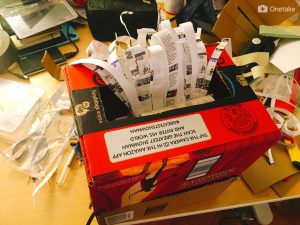
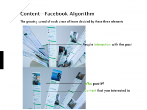
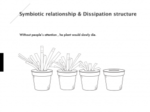
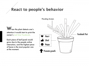
It is a plant-like product that represents the social media. For example, on Facebook. The posts you made on Facebook would be printed on a leaf. The growing speed of the plants would depend on the interaction activity of people passing by. The usual action we do on social media, like sharing, liking and commenting would respectively correspond to tearing part of the post. Without people’s attention or interaction, the social media plant would die, which shows the relationship between social media and people. The former relies on the input and attention from people, and the latter needs to build their identity with the public. Also, bringing the virtual action to actual physical ones exaggerates the bounce between the two vividly.


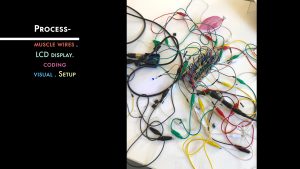
Technology
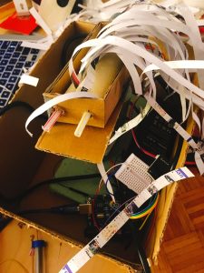
About the technology, I used many stepper motors for the roller system. I did a lot of tests on the motor speed and the paper material to simulate the most natural growing movement. I also use ultrasonic sensors and sound sensor to detect people’s presence and movement.
Slides:

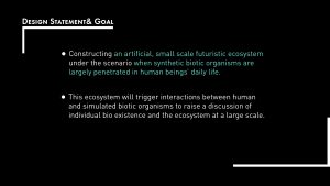
Concept + Goals:
A system that humans are party to, but not sovereign over.
Intended audience: I imagine this piece living in the gallery, the structures in this piece are seen not as inanimate, fixed objects, but as living entities, capable of regeneration and growth. The intended audience should be someone who is interesting in immersive installation environment and synthetic form.
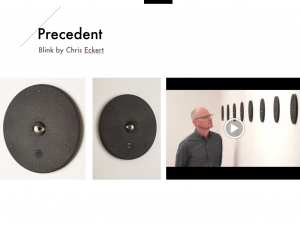
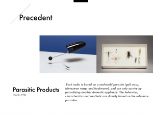
Precedents:
A breath of life by Fraser Ross | Atelier
Muscle wire projects by Jie Qi
Description of the project:
A.Sketch
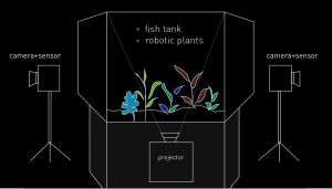
Before going into the implementation stage, I created sketches to illustrate the possible project scale and appearance. (Fig1.1)The outlook of the installation should look organic enough to make people think of cells or life form etc. Transparent glass and the customized base are being considered as important elements in this project, for both how it looks like as well as the setup detail. In Fig1.2., this diagram shows how this installation will be set up, and the layout of the components including robotic plants, camera or sensor, and projector. The camera will be used to capture audiences movements and the projector will be used to create an appropriate visual outcome. Since this is an interactive installation, the main input will be audience’s movement, which will trigger the robotic plants to respond to it. Robotic plants will be influenced by human factor, but will still have the random movement like real plants.
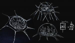
Figure 1.1. Project appearance sketch
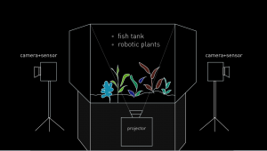
Figure 1.2. Project setup and layout
B. Technique
To generate a movement that is intriguing enough, the sensors in electronic components and multi-platforms are required. I want to connect Unity, Arduino, and Kinect these three platforms to complete the interaction. For each execution detail: Kinect– using the infrared camera to detect audience’s body skeleton and find the x, y, z-axis. Unity– using the c# program to enable the trigger function when audiences touch the certain area (there are five little yellow people models spread on the screen representing different location). When the models being triggered, Unity will send a byte to the serial monitor in Arduino. Arduino– in code, there is a processing message which will start to heat up the wire and rotate the motor, by typing “on” in the serial monitor, the function loop will start to run. To conclude, by connecting these three different platforms, I can achieve an indirect interaction without using a sensor. For the final setup, the audience will not see the unity interface so that they can just walk around, being captured by Kinect, and the robotic plants will move based on their movement without notice. The reason for putting all the technique together is to response the original idea for this project: a system that people can interact with in an indirect way.
C. Prototype and Playtest
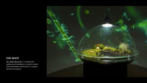
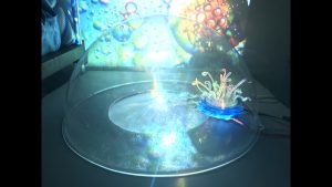
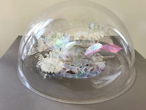
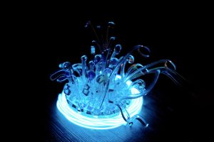
Through making a physical prototype, the main material for making robotic plants is the radiant acrylic. This is an important design decision being made— the acrylic itself representing cheap and mass production like what we can see in CD or any plastic product. However, the shimmer visual effect makes the robotic plant look futuristic, and it also fits into the context of “largely penetrate into our daily life”. I use laser cutting for customizing each plant, and also electronic components such as muscle wires, motors to create different movement.

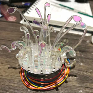
Figure 1.3. the first physical prototype with radiant acrylic and stepper motor
After the very first prototype, I found out the movement of the motor is too stiff, and I need to find the other components that can create natural movement. The muscle wire is what I chose in the end. It is a unique type of wire that acts like the muscles in our bodies. Muscle Wire is an extremely thin wire made from Nitinol (a nickel-titanium alloy) that is known for its ability to contract when an electric current is applied. I incorporated this component to my project, and there are some interesting precedents created with muscle wires that I got the inspiration from. For example, A breath of life by Fraser Ross, using Flexinol, recycled electronic components, specimen jars, these “flower lamps” reside in a state of death until human interaction — a breath — brings them to life for a brief moment. The blowing is the appropriate interaction as trees and plants grow on carbon dioxide. Every living thing needs a home, plants change themselves to survive in their habitat.
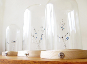
Figure 1.4.”A Breath of Life by Fraser Ross.”, 2010.
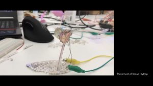
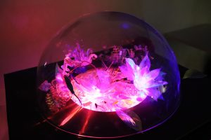
For my own creation with muscle wire, I tested out several prototypes to make a real-life look based on the shape of real plants, like a leaf, flower, and Venus flytraps (FIG 1.5). Using muscle wire is the most challenging part of this project, it’s really difficult to manage the right amount of electricity and there are countless wires to put together. However, after series of tests, I put all the components together and add the light effect to see the real set of the project and then conducted a primary playtest. At this stage, the primary project form and the aesthetics have already come out.
muscle wire movement prototype- venus flytrap
Based on the feedback I got from playtest, there are two aspects needed to be improved: first, the movement of wire and plants are not that clear, the movement is sparse and too gentle to notice. Second, the layout of plants are not well-formalized, they looked like individuals rather than a whole ecosystem.
D. Finalise
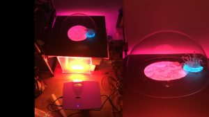
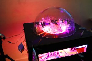
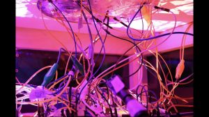
Consider the setup for the exhibition, I made a customize stand to store projector and all the electronic components inside. One another important decision is that I used transparent acrylic to reveal the wires and the circuits of this projects because I want people to feel the technology behind this piece as if those wires are the origin of robotic plants. Also, the depth camera used to capture human beings’ movements are decorated with robotic plants in order to make it fit into the project.
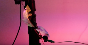
Figure 1.5. decoration on the depth camera
Reflection
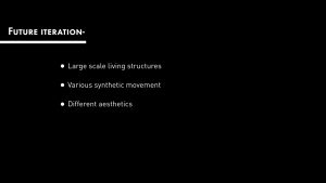
The criteria used to evaluate this project is mainly based on visitors’ behavior during the major major exhibition. The most frequent feedback I got from this project is that people enjoy its aesthetics, including lights and handcraft robotic plants. At the same time, people do feel want to interact with it and see what will happen, and they will want to dig more into the concept behind. The whole interaction takes people for 3 mins on average. Most of the feedbacks are positive, but one thing I think should be improved is that some people will neglect the movement because it happens randomly and there is no clear light resource to light up each component. The future iteration of this project will be the reassessment of the project scale, maybe the large scale living system can provide a more immersive experience.
List of components:
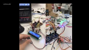
(there are more pins on Mega which enables me to connect 6 muscle wires, 1LCD, 8 LED lights, and 1 stepper motor, the total number of pins in need is 34. )
a nice substitution for Kinect, lightweight, easy to set up, and compatible with Mac environment. I was supposed to use Kinect 2 to track people’s skeleton but my windows laptop broke the night before the exhibition, so I change unity to openframework and Kinect to depth camera to create the desired outcome.
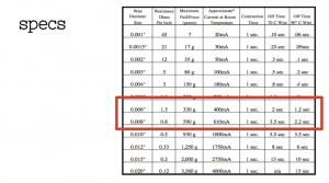
I bought tons of them on sparkfun. There are different specs and I think 0.012″ looks good, not too thin or too thick.
Presentation slides and Process:


Additional resource: For this project, I tried to gather all the useful information about using muscle wires, and I put them all in a google doc
Code: Code in Arduino on the GitHub
The goal of the project- Try the basic set up for final project form, and two robotic plants with different motion included. One is made with the stepper motor(Ferns) and the other one is muscle wire(Flytrap). In this iteration, I want to test the light and visual effect of this project as well as differentiate random and systematic movement of robotic plants. Also, one important implementation of this iteration is to add the interaction part, using Kinect and Unity to communicate with Arduino, audiences can interact with this set by walking around in the room.
Main components:
Arduino UNO
Xbox Kinect 2
0.012mm muscle wires
tip120
330-ohm resistor
12v stepper motors
motor shield for stepper motor
12v 6a power source
How it works:
For the demo can see the playtest video below. Kinect– using the infrared camera to detect audience’s body skeleton and find the x, y, z-axis. Unity– using the c# program to enable the trigger function when audiences touch the certain area (there are five little yellow people models spread on the screen representing different location). When the models being triggered, Unity will send a byte to the serial monitor in Arduino. Arduino– in code, there is a processing message which will start to heat up the wire and rotate the motor, by typing “on” in the serial monitor, the function loop will start to run. To conclude, by connecting these three different platforms, I can achieve an indirect interaction without using a sensor. For the final setup, the audience will not see the unity interface so that they can just walk around, being captured by Kinect, and the robotic plants will move based on their movement without notice.
Circuit and CODE:
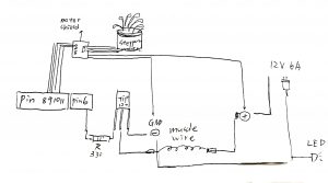
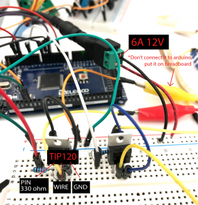
The following circuit includes the detail for connecting muscle wire correctly, note that there are two sides of muscle wires, one side should go to the middle leg of the transistor(TIP 120), and the other should go to the positive side, which is 12v 6a (+) in this circuit. The other two legs of transistor go separately to GND & resistor- Pin, the reason for pin leg output can actually control the transistor and open the circuit for electricity to go through the wire. Be very aware of the external power source, don’t connect it to Arduino unless you want to burn it. Just connect positive and negative side to breadboard like how you use 9V battery to power up the circuit.
CODE in Arduino:
#include <Stepper.h>
const int stepsPerRevolution = 200; // change this to fit the number of steps per revolution
// for your motor
// initialize the stepper library on pins 8 through 11:
Stepper myStepper(stepsPerRevolution, 8, 9, 10, 11);
String buf;
char c;
int flower=6;
int flower1=4;
int flower2=5;
int led = 2;
void setup() {
pinMode(flower,OUTPUT);
pinMode(led, OUTPUT);
// set the speed at 60 rpm:
myStepper.setSpeed(60);
// initialize the serial port:
Serial.begin(9600);
}
void loop() {
while (Serial.available() > 0) {
c = Serial.read();
if (c == ‘\n’) {
processMessage();
buf = “”;
} else {
buf += c;
}
}
}
void processMessage() {
Serial.println(“processMessage”);
if (buf.equals(“on”)) {
//0.005″wire
digitalWrite(flower,HIGH);
digitalWrite(led,HIGH);
//
digitalWrite(flower1,HIGH);
digitalWrite(flower2,HIGH);
delay(3000);
digitalWrite(flower,LOW);
digitalWrite(led,LOW);
digitalWrite(flower1,LOW);
digitalWrite(flower2,LOW);
delay(8000);
for(int i=0;i<6;i++){
// step one revolution in one direction:
Serial.println(“clockwise”);
myStepper.step(stepsPerRevolution);
delay(500);
// step one revolution in the other direction:
Serial.println(“counterclockwise”);
myStepper.step(-stepsPerRevolution);
delay(500);
}
}
}
Problem encountered:
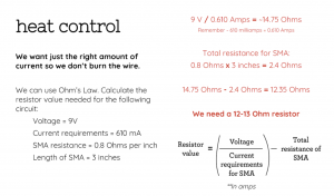
I spent a lot of time to caculate and test the right amount of electricity for the wire. Using the specs chart of wire and the formula of voltage caculation from computational craft class slides really help me alot.
For the playtest plan, I record a simple demo video to show the interaction. I would like to know people’s reaction toward the movement of plants, it’s interesting to look at or not. Also, I am curious about if they are aware of what interaction they are adding up to this system.
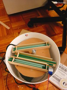
1. Physical object prototype with EL wire and 12v Stepper motor:
Using radiant acrylic as the main material, and then laser cutting the shape of robotic plants. To make it move I simply used a 12V stepper motor for a quiet and smooth rotation. There was a hole on the customized base of the plant which enables the plant to sit on the motor while rotating. To make it looked nice under the darkroom environment, I use EL wires to wrap the surface of the motor. Before using EL wire to create high contrast look, the plant looks like what showed below:
-Findings: After this prototype, I started to worry about how to create an interesting movement that will intrigue audiences. Stepper motor is quiet enough for a subtle movement, but I definitely need something more organic or mysterious.
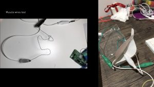
2. Muscle wire test:
I bought a 1feet, 1mm muscle wire from Tinkersphere, and used 5a 10v power source to heat it up by attaching to the alligator clips. The movement of wire is vicious! I tried to build a circuit using photocell and Mosfet to heat up the wire based on the light amount received by the photocell. I found the reference from a book Arduino Wearables (Technology in Action) 1st ed. Edition, there is a chapter inside talking about shape memory wires. However, the circuit doesn’t work because of the insufficient electricity from the 9V battery. After a long run research, I found out the 1mm muscle wire is too thick to heat up without a large amount of electricity. After this prototype, I started to seek ideal components for my project including 0.012 mm muscle wires, tip 120 transistor, and 12v power source. The next step will be testing out the most stable circuit to generate the movement I want.
Final project description:
Interaction/systems diagram:
Timeline with milestones:
week 1 (4/3-4/8)- basic functionality
week 2 (4/9-4/15)- Prototype
week 3(4/16-4/22)- Iterations
week 4(4/23-4/30)- Finalize
Precedents:
EPIPHYTE CHAMBER by Philip Beesley
UNMAKEABLELOVE by Sarah Kenderdine & Jeffrey Shaw
petting zoo by minimaforms
sensory desserts by Erika Marthin
Synthetic Polleniser by Michael Candy
The goal of this assignment:
Create a circuit with ultrasonic sensor and photocell to fulfill the following requirements:
List of components:
How it works:
How photocell works is to change analog voltage based on the amount of light received by the sensor. As the light level increases, the analog voltage goes up even though the resistance goes down. For the ultrasonic sensor, using echo and trig pin to detect the soundwave and then calculate the distance between object. Put all together in this circuit, the photocell will detect the light amount in the environment at first, and if it’s bright enough (depend on each photocell, the number change dramatically because it’s super unstable) the led won’t light up. If the distance between the object(hand) and ultrasonic sensor is less than 10cm, the led will light up. However, even if you cover the whole photocell to make the environment dark, the led won’t light up because of the && function in code. You still need to be close enough to the distance sensor to make it work.
Circuit:

CODE in Arduino :
const int trigPin = 13; //naming a constant value / giving a variable name / #define acts as a find and replace
const int echoPin = 12;
const int yellowLed = 8;
const int photocell = A0;
int light;
void setup() {
Serial.begin (9600);
pinMode(trigPin, OUTPUT); //trigPin is sending out the signal
pinMode(echoPin, INPUT); //echoPin is retrieving information, therefore it is INPUT
pinMode(yellowLed, OUTPUT); //trigPin is sending out the signal
pinMode(photocell, INPUT); //echoPin is retrieving information, therefore it is INPUT
}
void loop() {
long duration, distance, light;
digitalWrite(trigPin, LOW);
delayMicroseconds(2);
digitalWrite(trigPin, HIGH);
delayMicroseconds(10);
digitalWrite(trigPin, LOW);
duration = pulseIn(echoPin, HIGH);
distance = (duration/2) / 29.1; //Time it took for the echo to be received and divided in half then divided by the speed of sound
light = analogRead(photocell);
if(light < 700 && distance < 10){
// Serial.println(“work”);
digitalWrite(yellowLed, HIGH);
// wait for a second
}
else{
digitalWrite(yellowLed, LOW);
}
// Serial.print(distance);
// Serial.println(” cm”);
Serial.println(light);
// Serial.println(distance);
}
Problem:
The photocell is really unstable, I tried connecting two different photocells at first, and kept getting 1023 in my serial monitor. Only after I moved to somewhere really bright and opened up the third brand new photocell then I got the reasonable number from the serial monitor.
This week is to explore different motors. The first part of the assignment is to shortly describe the differences between DC motors, servo motors, and stepper motors. Basically, the DC motor is the one good for continuous spinning. It runs at a high RPM (revolutions per minute) and can be used for something like fan and blender. Servo motor is easy to connect and can generate high performance. The advantage of the servo is to control the rotation degree from 0-180. Otherwise, if the rotation degree exceeds 180, it will turn counterclockwise. General usage for servos can be robotic arms while its movement is rude along with the noisy sound. Stepper motor is famous for its precise controllability of rotation angles. Unlike servo motor, it can go around 360 degrees with its fractional increments. Stepper motor is good for steady, precise and quite movement such as the mechanism of 3d printing machines.
For the self-exploration about motors, I choose DC motor to make a hand blender.
The goal of the project: Using the potentiometer to control the speed of DC motor and make a mini blender.
Components:
1) Arduino
2) D.C. motor
3) NPN transistor TIP120 X1
4) Rectifier Diode X1 (I used 1N4001)
5) 1* 220 ohms resistor
6) 10K Potentiometer
7) Breadboard
8) Jumper wires
How it works:
Using the potentiometer( the adjustable resistor ) to change the speed of DC motor, as the value of potentiometer goes up, the motor will rotate faster. Circuit sketch: connect 1N4001 to pin3 and potentiometer to a0.
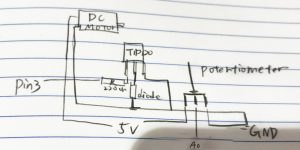
Code:
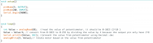
Very simple code, remember to transfer the value of potentiometer from 0-1023 to 0-255 to fit the capability of the output pin. you can use map function but I just roughly divided it by 4.
Problem: the most difficult part is not about the circuit, but the blender itself. Because the rotation speed can be really fast, my handmade blender was thrown out by the motor after 3 sec and I have to tight the blender with iron wire to the motor for several times.