Photocell+Ultrasonic Sensor+LED (Week 5)_Alyssa
Leave a reply
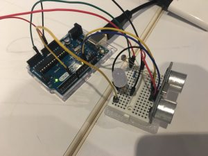
Create a circuit that the LED will light up only when the ultrasonic sensor detect something close and photocell sensor is covered.
1 * ultrasonic sensor
1 * photocell sensor
1 * LED
1 * 10k ohms resistors
1 * 220 ohms resistors
Wires & jumpwires
Arduino board
Get close to the ultrasonic sensor
Cover the photocell
LED light up
pcom/ultrasonic&photocell
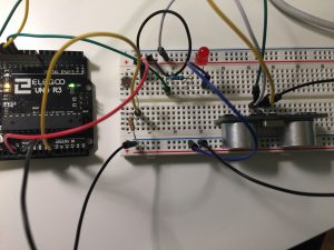
Create a circuit that activates an LED just when both photocell is covered and ultrasonic sensor has something close enough.
1x Arduino
1 x medium breadboard.
1 x red LED
1x ultrasonic sensor
1 x photocell
1x resistors (220 ohms) – resistor
1 x resistors ( 10K ohms) – photocell
Jump wires
By default the light is off (LOW). When the photocell is covered OR the ultrasonic detects an object the LED stays the same. Just when both are covered triggers the system to light up the LED.
I had to think through my if statements before coding.
Images of your circuit
https://github.com/Lywa/carla_molins_Pcomp/tree/master/WEEK_5_hw Continue reading
After learning about sensors, we were asked to combine the use of both photocell – love – and ultrasonic sensor using an if statement, and here is the result:
Continue reading
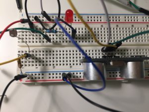
Goal of the project : Turn on the light according to distance and ambient light
Core components : Led light, photocell, 220 Ohm resistor, 1k resistor, ultrasonic sensor, arduino
How it works : the ultrasonic sensor measures the distance and the photocell measures the ambient light. An if statement combines the two measurements to control the led light
Problems encountered : the led light blink when is on. I couldn’t find a way to connect the photocell data without using a map function
Hello, after my initial two failures I’m back at it again with a copied code. This code is from my classmate Alyssa http://lizastark.com/physcomp/alyssas-combination-lock-week-4/ https://drive.google.com/file/d/1OlpTO_oNPYWVEbz0SmbbegJo1Oo0Lawy/view
My breadboard set up is still functional, though to match with Alyssa’s code I got rid of a button. Here are some videos of my experience:
In this video I am inputting the combination and finding that after the combination is inputted there is no way to get the Arduino to lock/ reset again.
Here I found that prior to putting in the correct combination, the buttons will reset themselves after 3 pushes.
Thank you.
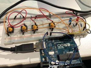
Goal: Build a combination lock using 2-4 buttons, at least 4 button presses, and LEDs indicating locked vs unlocked status.
Components: jumper wires, 3 buttons, 5 resistors (220 Ohms x 2, 10K Ohms x3), 2 LEDs (different colors), breadboard, arduino
Setup: 3 buttons and 2 LEDs with resistors wired to arduino. When the right combination of buttons is pressed, unlock and shine the green LED. Otherwise, lock and shine the red LED.
How it works:
Starts in a locked status, indicated by red LED.
Enter the following combination of buttons to unlock:
Button 1: 2 presses
Button 2: 1 press
Button 3: 2 presses
This combination unlocks, indicated by green LED.
To lock: press each button once. This triggers each button count to exceed the maximum limitation and thus reset to 0.
Create a circuit to light up a LED or control a Processing sketch using both a photocell sensor and an ultrasonic sensor.