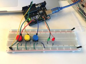
The goal of the project was to create a locker that green LED opened when the right color code was pressed. The red LED opened while the code remains wrong.
Components
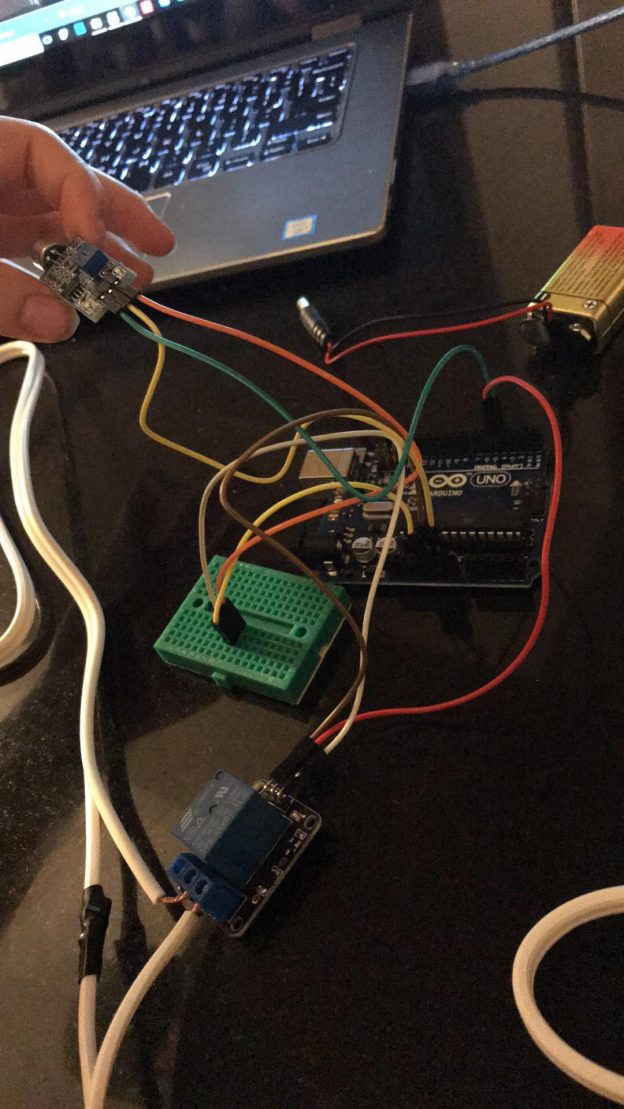
1x Arduino
1 x breadboard.
1x green LED
1 x red LED
3 x buttons
2 x resistors (220 ohms) – resistors
4 x resistors ( 10K ohms) – buttons
Jumper Wires
How it works:
If it is in the right sequence, green LED will open
Press the button sequentially once a time with no repeat
Green led means unlocked (right), red led means locked (wrong)
Code:
const int blue = 3;
const int red = 4;
const int yellow = 2;
int ledRed = 13;
int ledGreen = 9;
int lastRed = LOW;
int lastBlue = LOW;
int lastYellow = LOW;
int i = 0;
void setup() {
// put your setup code here, to run once:
pinMode(blue, OUTPUT);
pinMode(red, OUTPUT);
pinMode(yellow, OUTPUT);
}
void loop() {
int redState = digitalRead(red);
int blueState = digitalRead(blue);
int yellowState = digitalRead(yellow);
if (redState == LOW && lastRed == HIGH) {
if (i == 2) {
i = 0;
} else {
i = i + 1;
}
}
if (blueState == LOW && lastBlue == HIGH) {
if (i == 2) {
i = 3;
} else {
i = 0;
}
}
if (yellowState == LOW && lastYellow == HIGH) {
if (i == 3) {
i = 4;
} else {
i = 0;
}
}
if (i == 5) {
digitalWrite(ledRed, LOW);
digitalWrite(ledGreen, HIGH);
}
else {
digitalWrite(ledRed, HIGH);
digitalWrite(ledGreen, LOW);
}
lastRed = redState;
lastBlue = blueState;
lastYellow = yellowState;
}