I want to control the light in different rooms.
Use IR sensor to control the brightness of LED, and turn on/off of LED
Core components
1* IR sensor
1* remote control
2* LED
2 * 220 ohms resistors
Wires & jumpwires
Arduino board
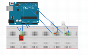
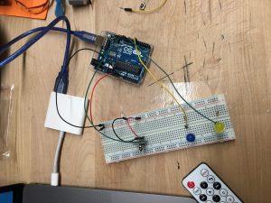
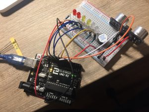
Circuit/Schematics
How it works
Button 1 : switch on/off of blue LED
Button 2 : switch on/off of yellow LED
Button + : increase brightness (++ 50)
Button – : decrease brightness (- – 50)
Two LEDs have different on/off state, but have the same brightness.
Problems
Two LEDs can’t be adjusted separately
The remote control is inaccurate
Choose one of the wireless topics covered in class and put it to practice for use in everyday life. For example, use the IR sensor with a remote control to make a fan for a hot summer day.
Document your project in action and post to the class blog, including the list of materials used, a circuit schematic, and notes regarding wins and challenges.
For a very long time, I have been fascinated by e-textiles because they lie at the intersection of craft and electronics. I did not know where to begin my exploration from and decided to follow along a simple Sparkfun tutorial to make a light-up plush (https://learn.sparkfun.com/tutorials/light-up-plush)
Materials required
Lilypad ProtoSnap
3V Coin Cell Battery
Conductive thread
Needle
Plush pattern
Felt piece: 10 by 10 inches
Scissors
Fabric glue (optional)
Beads, pompoms, ribbons, buttons, glitter to decorate
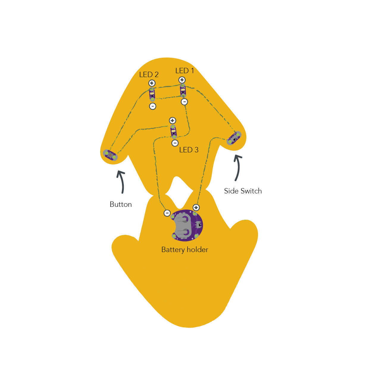
Diagram (taken from the Sparkfun website)
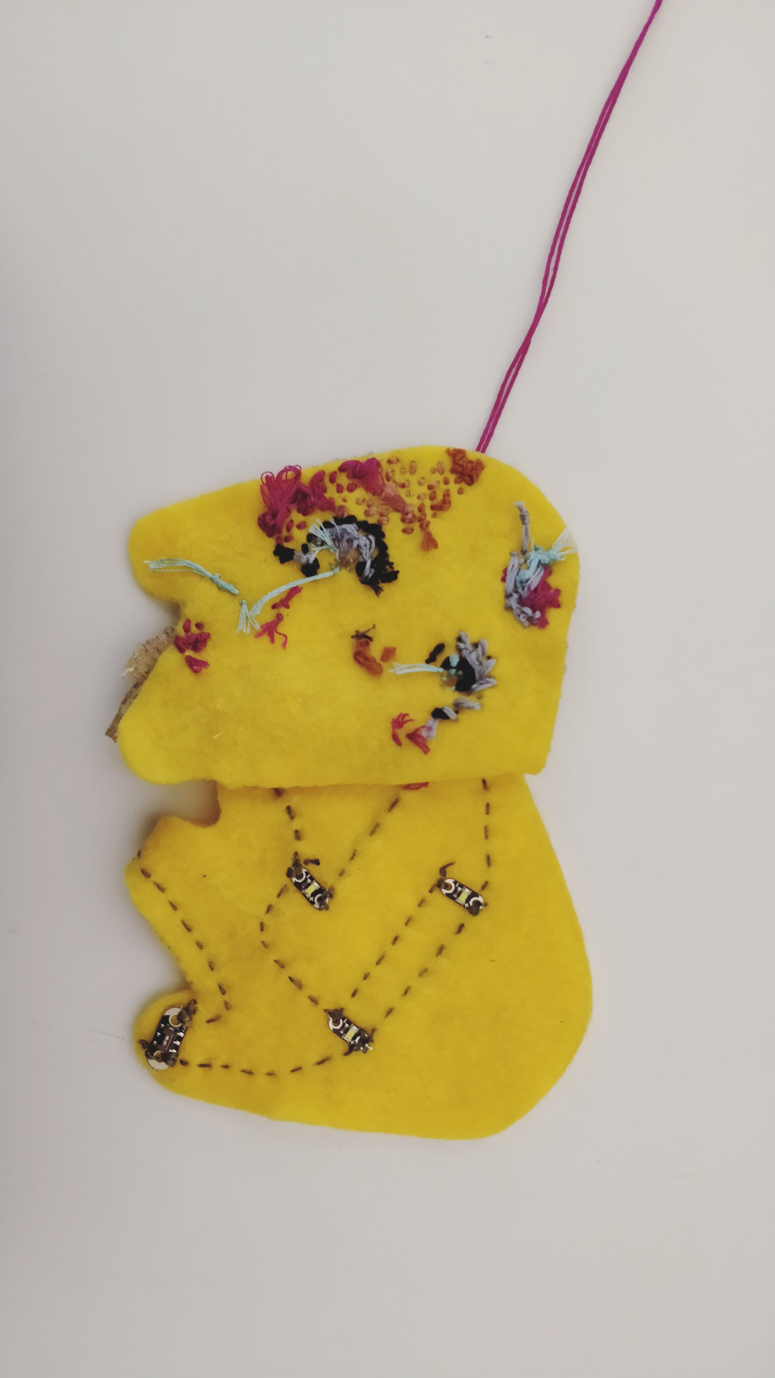
Description of assembly
Cut the plush pattern from the piece of felt
Arrange the Lilypad ProtoSnap components on the pattern.
Using conductive thread, make secure connections (loop around each tab at least 3-4 times) between the positive tab of the battery holder and one of the tabs of the switch.
Connect the other side of the switch to the positive terminals of the top two LEDs that make up the eyes, and finally to one of the tabs of the button.
Continue stitching, from the other side of the button to the positive tab of the last LED.
Connect the negative sew tab of the first LED, with the second, through the third to the negative sew tab of the battery holder.
Insert the battery, debug, and keep experimenting!
How it works
I was surprised to find that working with e-textiles isn’t very different from working with the Arduino hardware. It is based on the same principles of electronics that we are familiar with. A 3V coin cell powers the circuit, and the electrons, regulated through the side switch and the button, light up the LEDs.
Challenges
I had difficulty debugging my circuit. Unlike a “traditional” circuit, it was time-consuming to check the connections- as I had to re-embroider entire sections. Later I realized, that my circuit was getting shorted because of the long, untrimmed pieces of wire. After securing a few connections, and trimming the ends, it started working!
Future Iterations
I am excited about incorporating physical elements or characters in the process of digital storytelling. I feel they make the story more compelling. I was imagining a choose-your-own-adventure story, that plays out on the screen, depending on one’s choices in the real world. So these characters could act as controllers that are affecting the narrative. Continue reading →
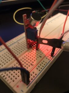
The intention with this project was to explore the infinite creative possibilities of playing with the relations between light and sound using a microcontroller. In this particular case, I wanted to explore new sensors such as BIG sound as input that triggers other process such as turning on and LED.
List of Components:
x1 Arduino Uno
x1 Breadboard
x1 Big sound module
x1 RED LED
x1 220 kohm Resistors
Jumper Wires
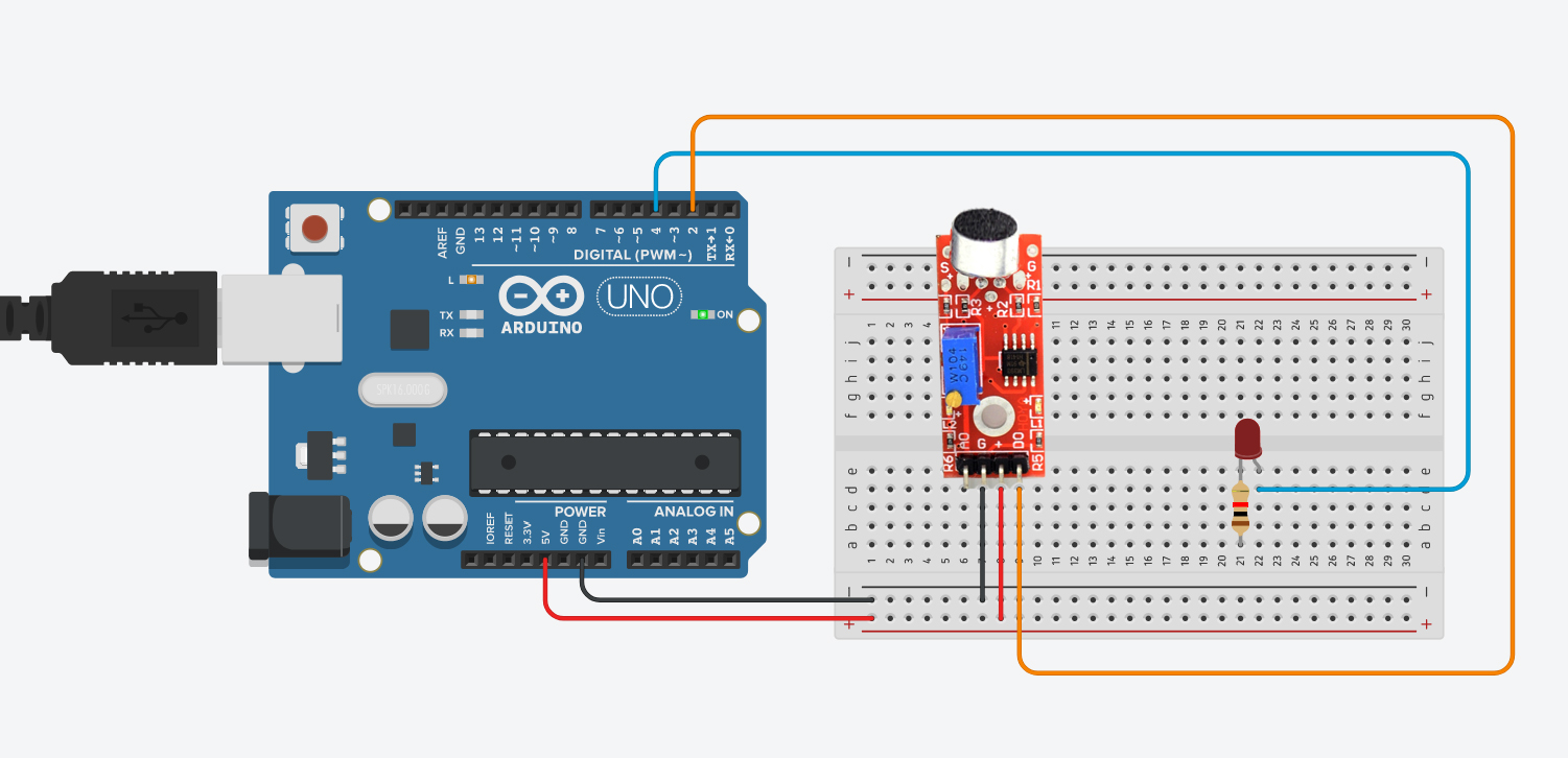
Assembly Process:
To create this project, first, the big sound module has to be connected to Arduino (We can use a Digital pin or Analog Pin. In this case, we used the digital pin 3, but we need to tell Arduino we are using it as DIGITAL input). Then we connect the LED to a digital pin 4 as an OUTPUT.
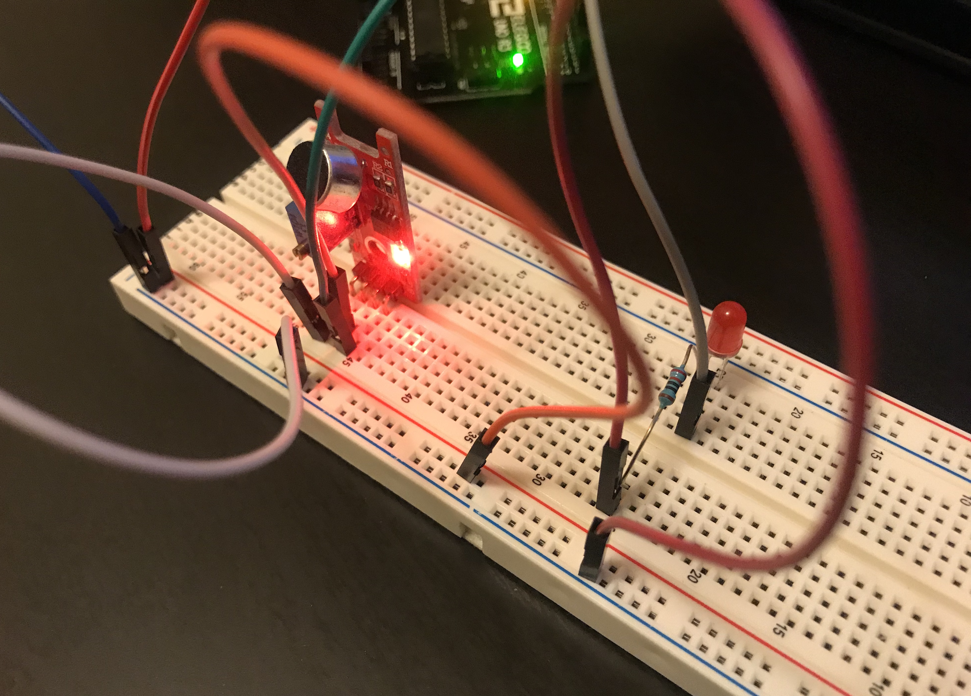
How it works:
To test the Big sound module, the 2 LEDs of the module will light up. In order to control the sensibility of the module, we need to move the built-in potentiometer in the module using a screwdriver. The idea is to turn it to the left to reduce resistance and add sensibility. As soon as the led turn off, that means the module is ready. Then we connect an LED to a pin and set it as OUTPUT. The result? The LED will respond to the high and low frequencies received from the sounds from the surroundings.
Problems:
Controlling the sensibility of the bid sound module represented a challenge. I wasn’t able to get an important sensibility value in order to control the LED. To test it, I had to create sounds with deep basses and had to be fairly loud. I also test the “small sound” module and the issue was even worst.
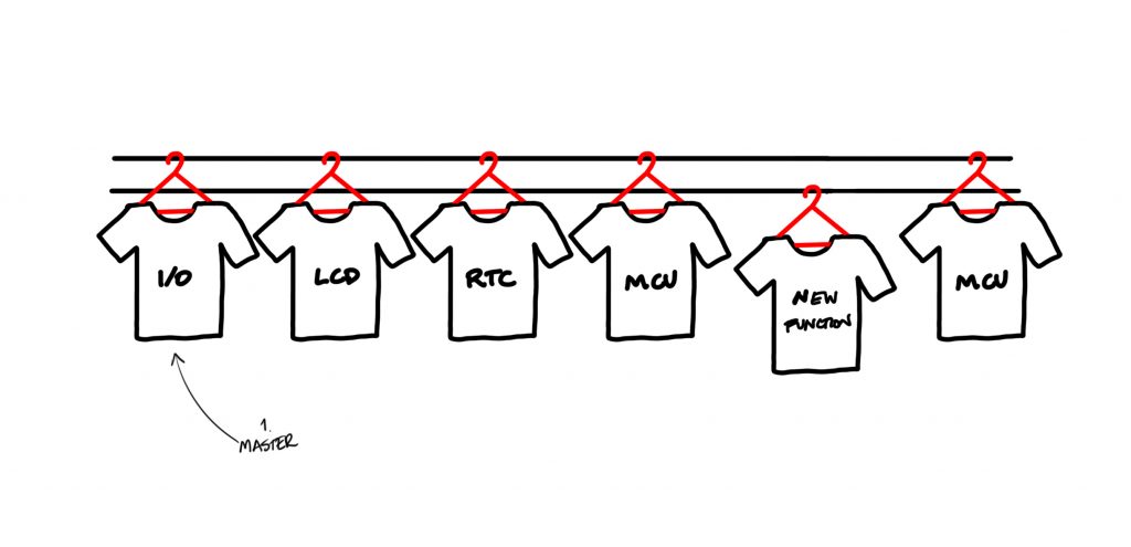
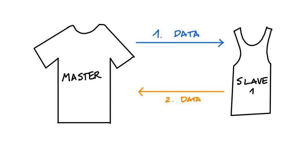
Or Inter-Integrated Circuit is a protocol that allows to connect multiple “slave” devices to a one “master” device. It’s the most used between electronic devices (microcontrollers, sensors…cellphones, cars…). The connection between a microcontroller (Arduino) with sensors and modules are good exaples of Master-Slave relation, where both can communicate to each other, but the communication is initiated only by the master.
Pros:
Only requires 2 wires that can support multiple devices for the communication (bus connection) up to 127 devices.
and it stands for universal asynchronous receiver/transmitter, it is one of the fundamental/basic ways of communicating the serial to another information source wirelessly. Continue reading →
Brief: After this week’s lesson about light and sound I wanted to find a project that would further enlighten me to the logistics of how sound can be sensed and a subsequent automatic action can be taken. The first idea for a project that came to mind was to use a vibration/sound sensor to sense a sequence of wave lengths and subsequently signal this information to us by lighting up a line of LED lights with escalating levels of brightness. Though that was a bit much for a novice like myself. Ergo, I thought pursuing something of a practical and simpler fashion could be very informative, like turning on a light fixture by clapping.
Goal: Conclusively, the goal of this weeks assignment is to assemble an arduino system that can sense a clap and automatically turn on an LED/light. Hopefully I will be able to personalize the clap rhythm or code that will turn on the light.
Assembly:
Materials:
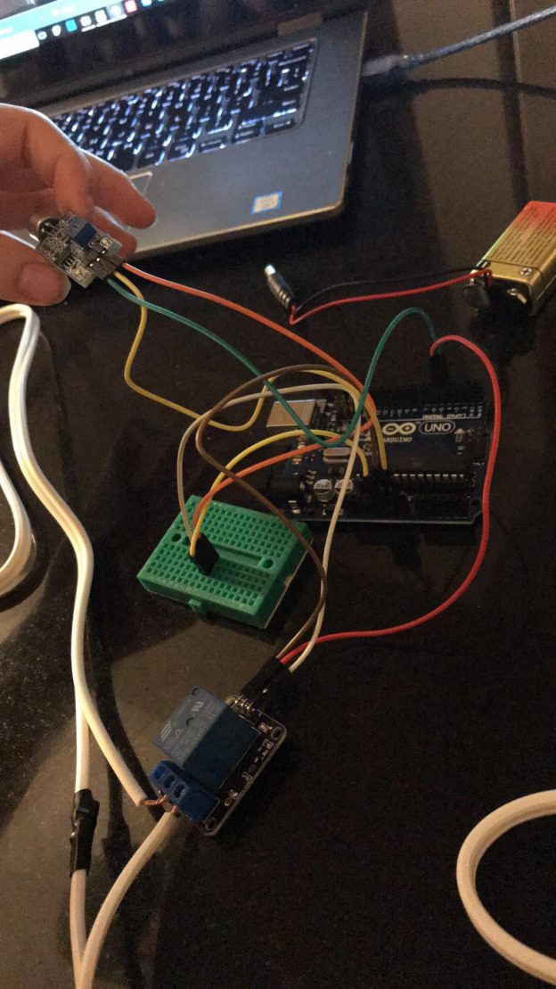
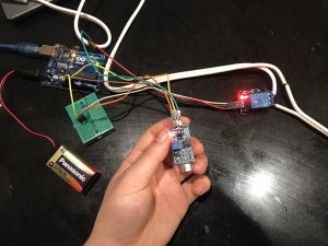
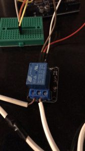
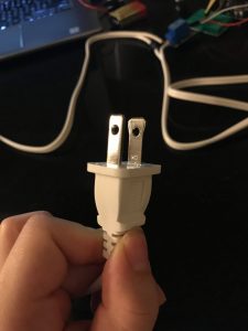
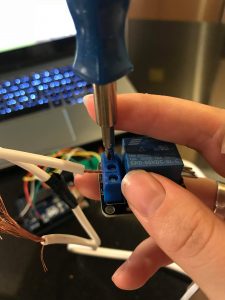
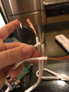
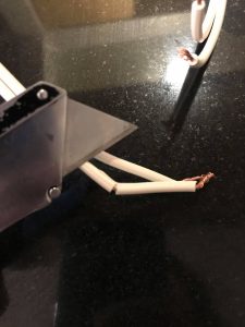
Arduino Board, Relay Module, Sound Sensor, 9V Battery, F to M Jumper 6x, M to M Jumper 1x, Breadboard, Battery Cable, mini screw driver, wire strippers and two prong light fixture.
The biggest problem I had with this project was due to my own lack of knowledge. In the very informative and simple video tutorial of how to make a clap sensing light switch the architect does not articulate which of the two wired cables are neutral and live (probably because most people know, but I didn’t). Accordingly, my first time around I didn’t connect the live to the relay module, instead I connected the neutral so initially my light didn’t turn on at all. I was stumped and very discouraged by the 2nd time I had taken it apart and put it back together again. The next day I did some research on how to fix cords chewed up from pets and during this tutorial I learned that in addition to my neutral and live connection problem I probably damaged the wires post stripping. By the third trial I had made a solid connection and miraculously the light turned on and could sense my clapping… snapping, and any high pitched double ” bang.”
Images:
7) Insert the Read More quicktag, otherwise your post will go one forever.
The goal of the project and/or desired interaction
The assignment was to adapt one of the light and/or sound circuits we built in class for another creative purpose. I choose to use the ultrasonic sensor to make an interaction with the buzzer and the LED lights.
A quick description of assembly and list of core components— 1x Arduino Uno
– 1x Breadboard
– 1x HC-SRO4 Ultrasonic Sensor
– 1x Buzzer
– 2x Green LEDs
– 2x White LEDs
– 2x Red LEDs
– 7x 330-ohm Resistors
– Jumper wires
How it works
When you move away from the ultrasonic sensor, the buzzer and LED lights will not light or make a sound. If you go closer to the ultrasonic sensor, the LED lights will light up and the buzzer will get louder.
Any problems you encountered and/or solvedAt first, I wasn’t sure how to exactly get the sound to get louder as I move nearer to the ultrasonic sensor. But I looked at some code and figured it out.
It is a synchronous data transfer technique which means there is a dedicated clock signal generated by the bus controller. It supports multi-master bus support and bidirectional transfer. It is a serial data protocol used by microcontrollers for communicating one or more peripheral devices quickly.
There is usually always one main master device controlling many other peripheral devices.
MISO (Master In Slave Out) – The Slave line for sending data to the master
MOSI (Master Out Slave In) – The Master line for sending data to the peripherals
SCK (Serial Clock) – The clock pulses which synchronize data transmission generated by the master
and one line specific for every device:
SS (Slave Select) – the pin on each device that the master can use to enable and disable specific devices.
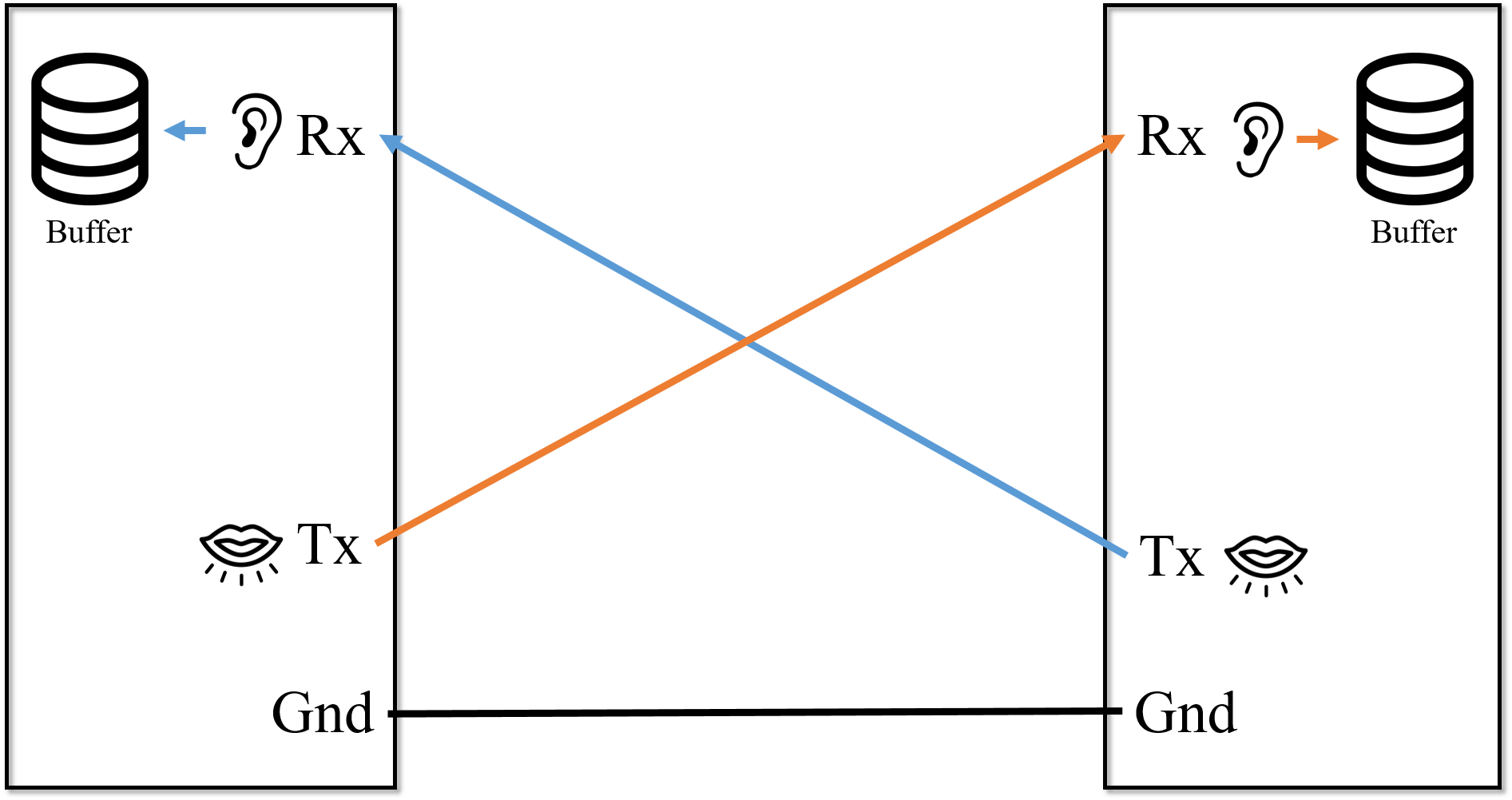
Draw a diagram or illustration that shows how it works.
Give at least 2 examples of when you use this protocol.
For example, SD cards and wireless transmitter both use SPI to communicate with microcontrollers to communicate without interruptions.
Universal Asynchronous Receiver / Transmitter : One of serial communication standards that Arduino can do with other devices. Its principle is similar to the conversation between two people. In order to have conversation, we need ears to hear, and mouth to talk. What one person talks through mouth goes to the ears of the other person. In this context, we can compare ears to RX(Receiver), and mouth to TX(Transmitter). The point is this: the data coming out of one side of TX(mouth) goes to other side of RX(ears), not TX(mouth). Which means, between different devices, RX and TX should be cross-linked.
In addition to RX and TX, electronic devices need to be linked ground to ground. Because each device has its own electric potential, unless one device’s ground is connected to another device’s ground, the data transmitted cannot be received correctly.
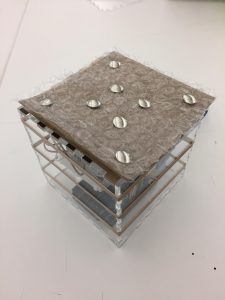
Music box that creates different tones through 8 different capacitive sensors (tags). I wanted to try out a different interface for the instrument that provided a tactile experience too.
Quick description of assembly and list of core components