UART
Universal Asynchronous Receiver / Transmitter : One of serial communication standards that Arduino can do with other devices. Its principle is similar to the conversation between two people. In order to have conversation, we need ears to hear, and mouth to talk. What one person talks through mouth goes to the ears of the other person. In this context, we can compare ears to RX(Receiver), and mouth to TX(Transmitter). The point is this: the data coming out of one side of TX(mouth) goes to other side of RX(ears), not TX(mouth). Which means, between different devices, RX and TX should be cross-linked.
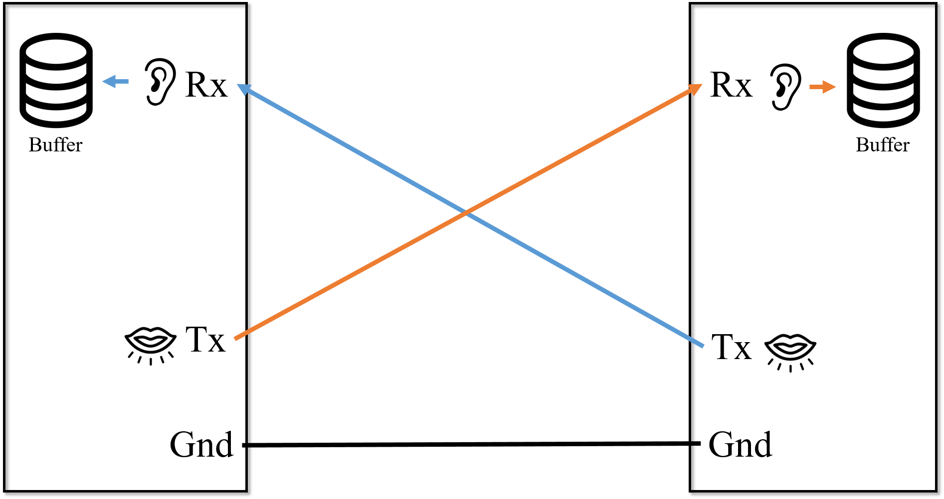
In addition to RX and TX, electronic devices need to be linked ground to ground. Because each device has its own electric potential, unless one device’s ground is connected to another device’s ground, the data transmitted cannot be received correctly.
One other point of UART is, it is required to harmonize baud rate between two devices. Here is where UART protocol is used due to the “asynchronous” feature of two different devices. Each electric device has its own “clock,” which is like a heartbeat of human, representing processing speed. For example, Arduino board and laptop have a huge difference in processing speed. If Arduino send data in its own clock cycle to the laptop, the data received by laptop will be read in a mess way because they are not synchronized.
Thus, there is a need to make a contract, for example, “let’s transmit and receive 9600 data in one second.” That would be a baud rate: the number of data transmitted/received in one second. If two devices’ baud rate is same, the entire data will be transmitted and received accurately.
Here is one example of using UART. When the user input data in serial monitor by keyboard of computer, then the Arduino board is echoing the same value. We can see when the baud rate is harmonized between two devices, even if they have different process speed(synchronized), they can transmit/receive data properly.
code : https://github.com/minhyekwak/picom-UART/blob/master/code2
Here’s another example of using UART to control LED by computer. This is a circuit and code that if user keypress 1 on computer, LED lights up, and if user keypress 0, then LED turns off.
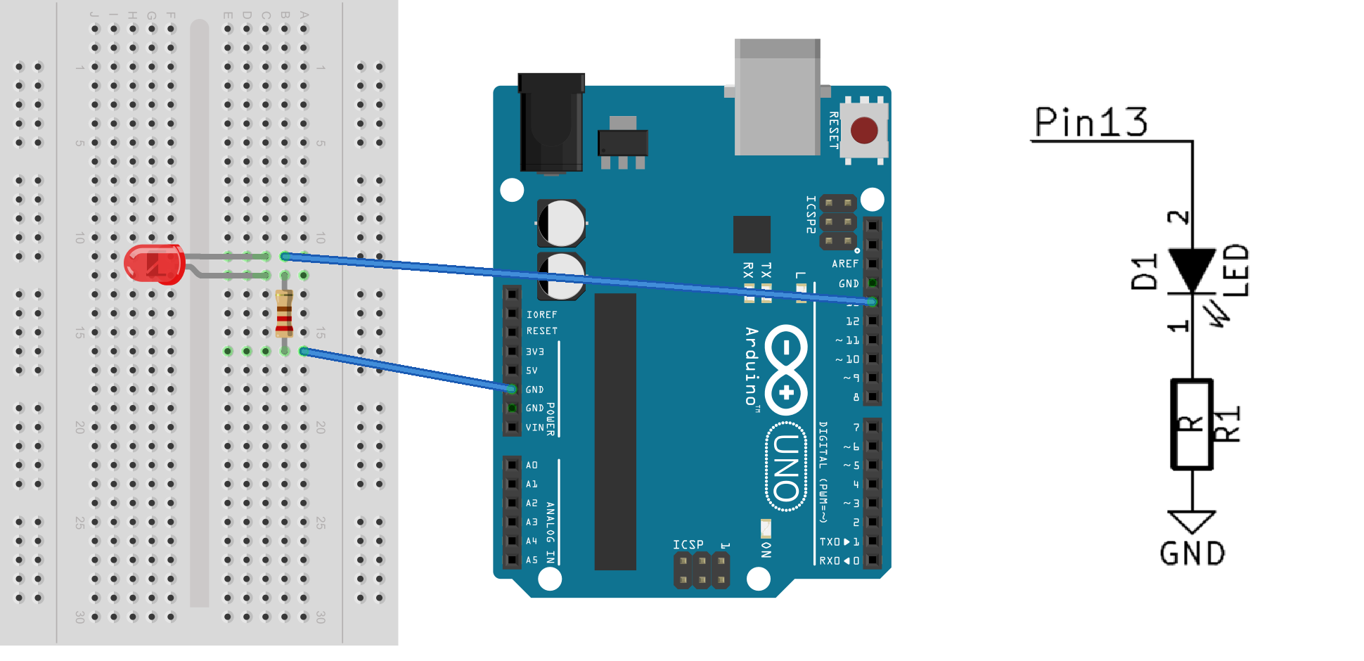
code : https://github.com/minhyekwak/picom-UART/blob/master/code