In preparation for week 7
Leave a reply
Goal:
The goal of this project is to use Capacitive sensing + piezo to create a song.
Components:
LCD x1
photocell x1
arduino board & breadboard
potentiometer x1
GitHub: https://github.com/joycemolly/cc-lab/blob/master/Use%20Capacitive%20sensing%20%2B%20piezo%20to%20create%20a%20song.
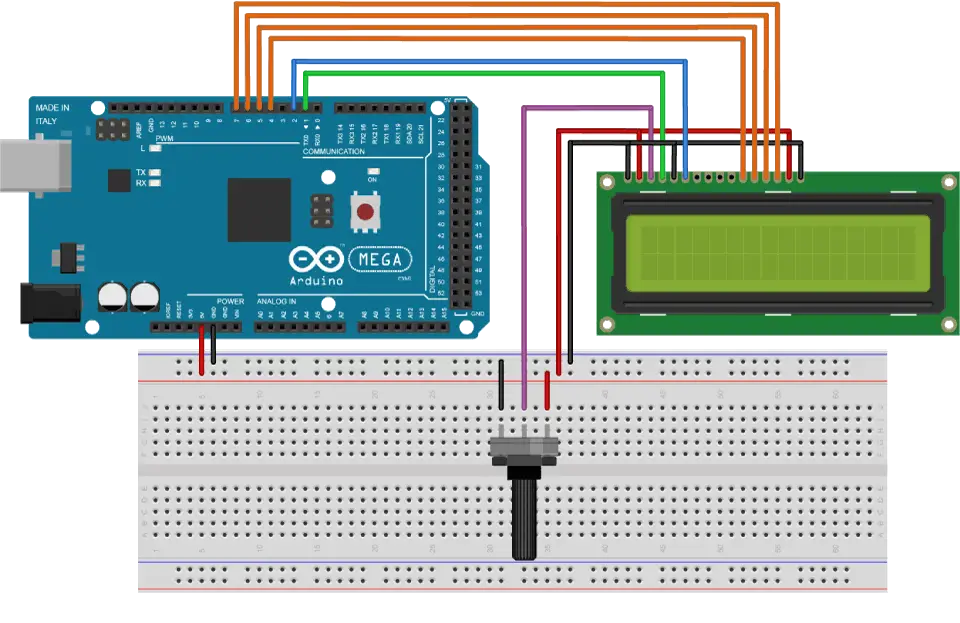
How the LCD works:
Goal:
List:
Arduino Code:
https://github.com/yuemelz/pcom2018/blob/master/photocell_distance.ino
Goal of the project:
using two of three buttons to create a code then turn on or turn off the LEDs.
List:
button x 3
blue LED x 1
yellow LED x 1
resistor x 5
Arduino code: pcom2018/3buttons.ino
https://github.com/yuemelz/pcom2018/blob/master/3buttons.ino
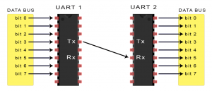
Contrary to the assignment, a UART also known as the Universal Asychronous Receiver/Transmitter is not a communication protocol, but a physical circuit that transmits and receives data through the serial port. Though similarly to protocol like SPI and I2C, UART is another method to transmitting and receiving serial data from other devices. This transaction of serial data or dialog between devices is an electronics form of language, in other words communication protocols. UART (according to circuitbasics) is a relatively old communication method and like stated in its name, is asychronous language. In computing, Asychronous indicates a dialog between UARTs is defined by a start and stop notification in a data series versus a clock that synchronizes the output to the receiving UART. A UART and a I2C can send a limited amount of bits (1 start bit, 5 to 9 data bits, an optional parity bit, and 1 or 2 stop bits), these messages are called packets.
How a UART works is that it will receive data in a parallel form (all at once through multiple points) and the UART(1) will translate the data into a packet to which it will transmit the data to the receiving UART(2) in series (one after the other on a single line). The receiving UART(2) will then translate the data (discarding the start and stop bit) and send it in parallel to the external data bus.
One of the more popular advantageous attributes that UART features includes: it uses only two wires to transmit data to another device (TxD: Transmit Data –RxD: Receive Data), uses a parity bit for error checking, data packet can be changed, contains a serial buffer (extra storage space so it can do other tasks while waiting for data), and is a pervasively used and accepted method (found in most processors). These attributes make UART a great communication protocol/mode, nevertheless their convenience do have their foibles. Some disadvantages include the data frame is limited to 9 bits, does not support multiple slaves/ master systems, and the baud rates (reading speed) must be within 10% of the transmitting and receiving UARTS.
Most (all) processors have a UART because of their simplicity in communication transmission, some processors include Raspberry Pi and computers. Though in more sophisticated CPUs the UART chip has become dispensable because the software of the outputted transmission can regulate the process instead of hardware, this technique is called bit-banging. (not completed yet)
Adapt one of the light and/or sound circuits we built in class for another creative purpose.
You must use a sensor of your choice to control the screen display (LCD or in Processing), light (multiple LEDs) or sound (using tone() and a buzzer or connecting to Processing) in your project. Post it to the blog in the required format.
Note: You should use assignments as opportunities to explore new components, connections, and programming concepts. They are intentionally open-ended in order for you to pursue a topic that interests you and to challenge yourself, both technically and conceptually.
Note 2: Don’t forget that we do have other sensors in the locker. I encourage you to explore them.
As part of the wireless presentation next week, we will learn more about different Serial communication protocols. You know serial from the serial monitor and debugging, but there is much more that you can do other than reading data. In preparation for this, everyone should complete this assignment.
Choose ONE of the following serial communication protocols and research it: UART, SPI, or I2C
Bonus: Do this for all three of the listed protocols.
ITP’s Physical Computing site is a good place to go if you don’t know where to start.
Goal:
The goal of this project is to build a LED light that will light up when the environment is dark and senses people approach.
Components:
red led x1
green led x1
resistor(200Ω) x1
resistor(10kΩ) x1
photocell x1
arduino board & breadboard
How it works
The photocell will first sense the light in the room. If the data is less that 700 and the distance that UltraSensor sense is less that 10, the light will turn on.
Code: https://github.com/joycemolly/pcomp–lock-combination/blob/master/homeworkLock.ino
Goal of the Project:
The intention with this project was to explore the capabilities of sensors connected to an Arduino, and how with the transformed data it is possible to create statements (conditionals) to achieve different purposes. In this particular case, the proposal was to create conditionals by mapping the values of a distance sensor and a photoresistor in order to light up or turn off and Led.
Conditions:
List of Components:
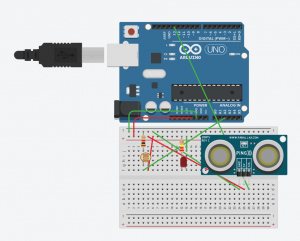
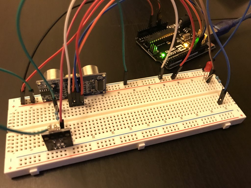
Assembly Process:
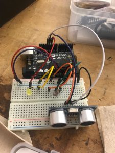
A good practice to create this circuit consists to connect each sensor (one by one) and check if the microcontroller is reading the data and is doing it correctly. First, the LED is connected, positive side to pin 11, and negative to a 10kohm resistor and ground. The Distance Sensor Trig and Echo are connected to pins 13 and 12 respectably. The photoresistor is connected to the Analog Pin A0.
How it works:
The Arduino program is constantly reading 3 conditions: If it’s bright (more than 30 for the photoresistor sensorValue), then the LED is off (LOW). if (sensorValue > 30), then: digitalWrite(led,LOW). If it’s dark and the distance to the sensor is more than 10cms, then the LED is off (LOW). if (distance > 10 && sensorValue < 30), then digitalWrite(led,LOW). Finally, if it’s dark and the distance to the sensor is less than 10cms, then turn on the led (HIGH). if (distance < 10 && sensorValue < 30), then, digitalWrite(led,HIGH).
Problems:
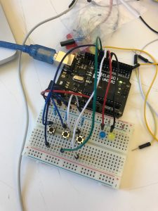
The main issue doing this exercise was trying to understand the Photoresistor I had available. The one that I have it’s from Elegoo and it has 3 connections instead of 2. In this case, it’s a bit more convenience when I want to connect the different wires to the breadboard and to the Arduino. I just had to check the “info-sheet” of the product.

Arduino Code (File):
https://www.dropbox.com/s/wb1e1fnj43sxcen/DarioNarvaez_HW_5.ino?dl=0
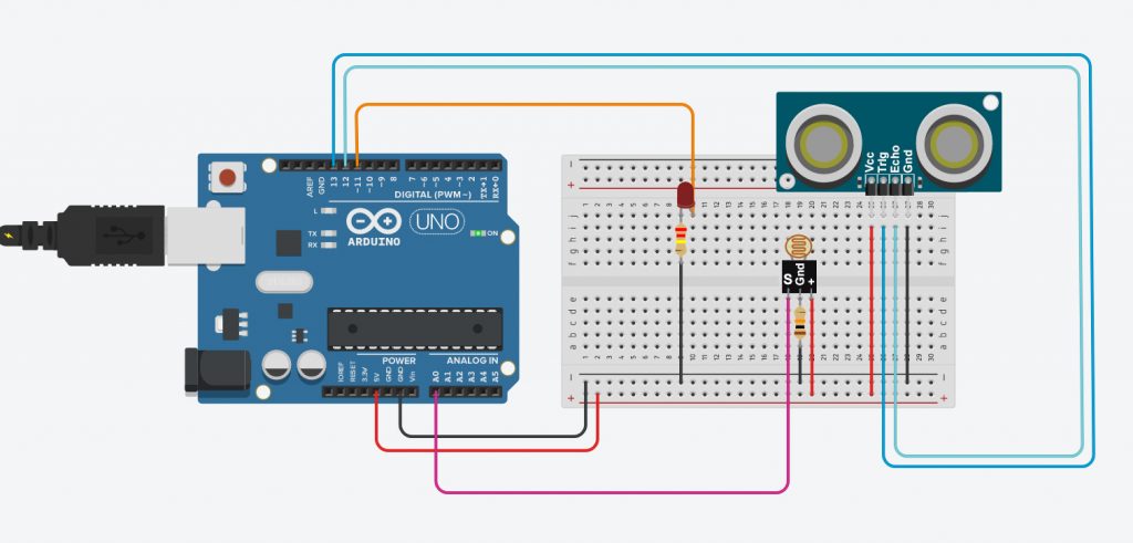
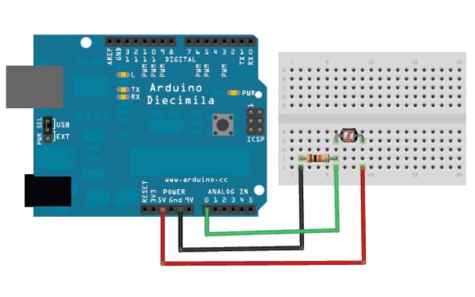
Circuit Diagrams:
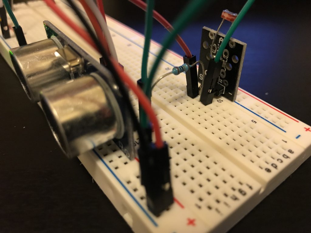
Alternative Photo-Resistor Connection:
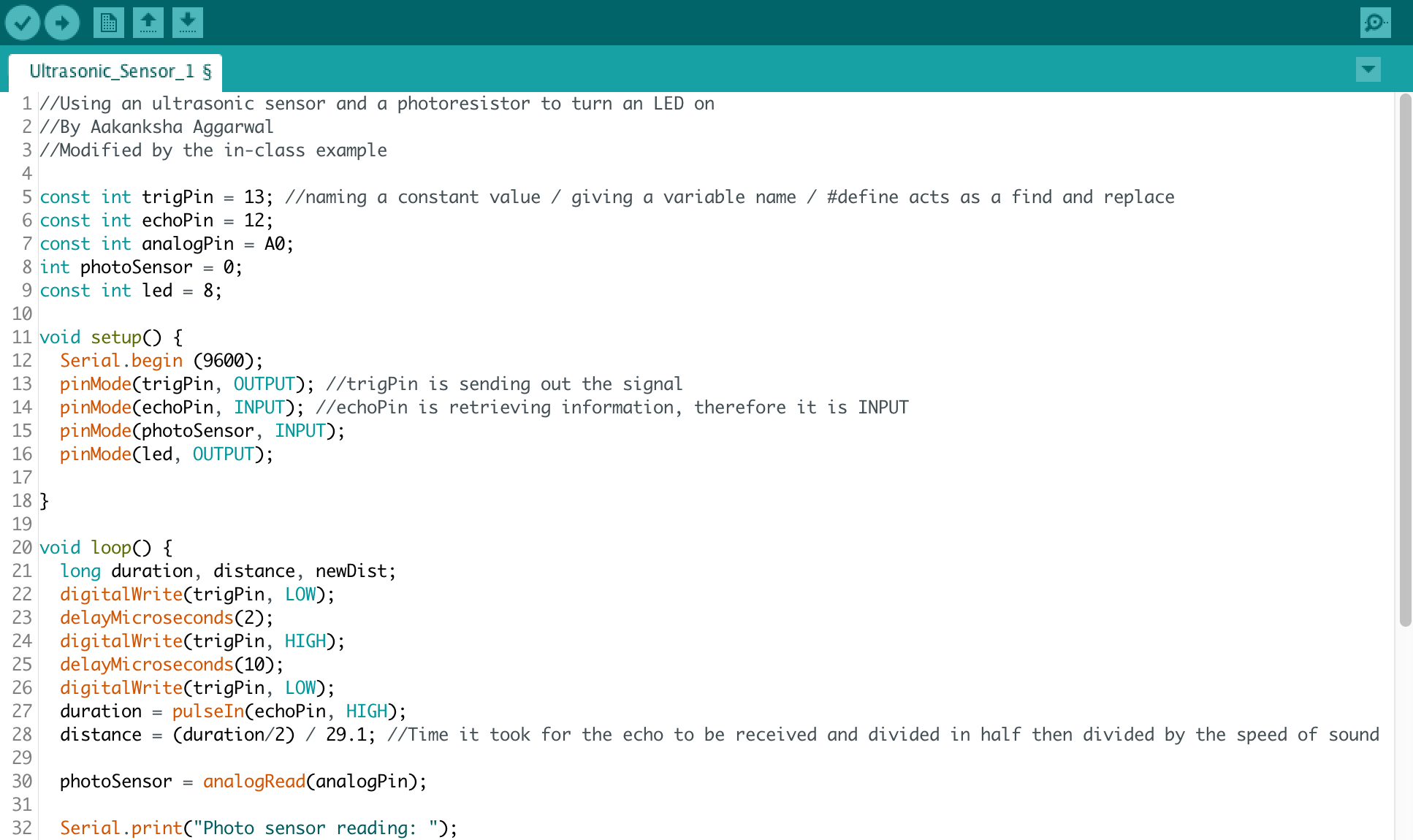
This week’s assignment was to create a circuit, where an ultrasonic sensor and a photosensor are used to control the state of the LED. Only when certain conditions are met for both, does the LED turn on.
List of Materials
1 x Elegoo Uno R3
1 x Full sized breadboard
1 x HC-SR04 Ultrasonic sensor
1 x Photocell (or photoresistor)
1 x LED
Resistors: 1x 220 Ohms (for the LED), 1 x 10K Ohms (for the photocell)
Jumper wires
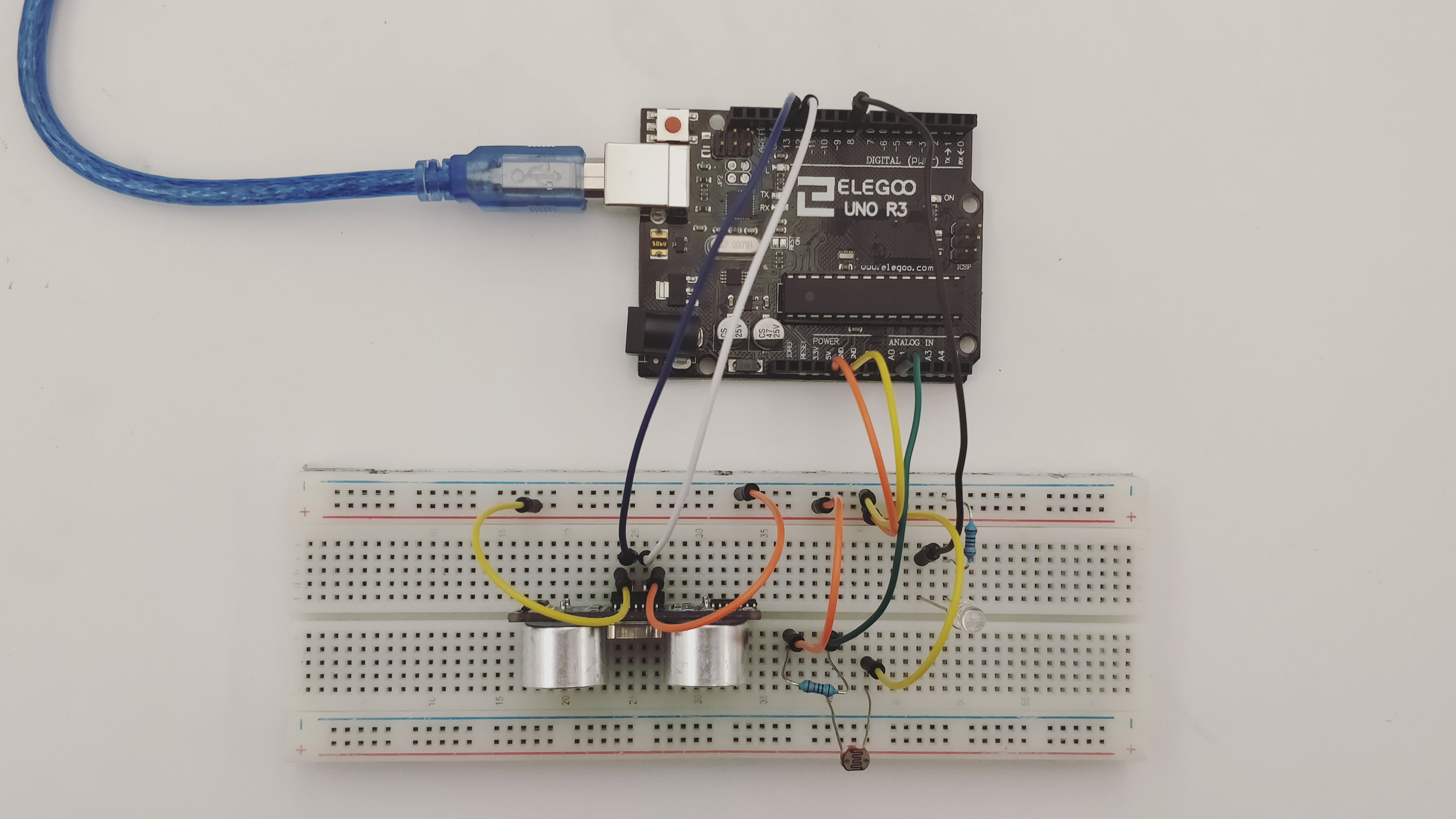
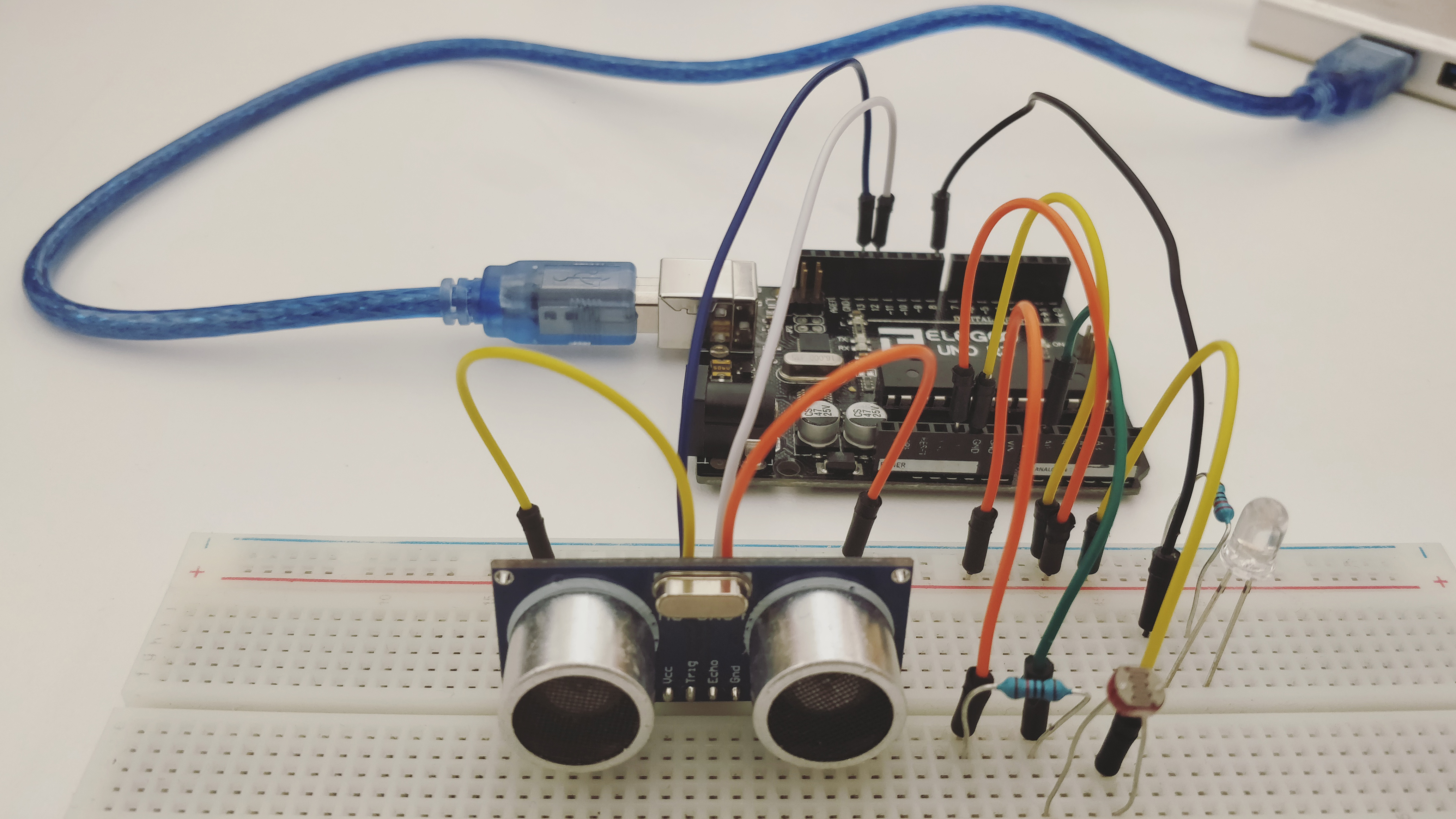
Description of assembly
Fritzing Diagram (Using the open source, free software available at http://fritzing.org)
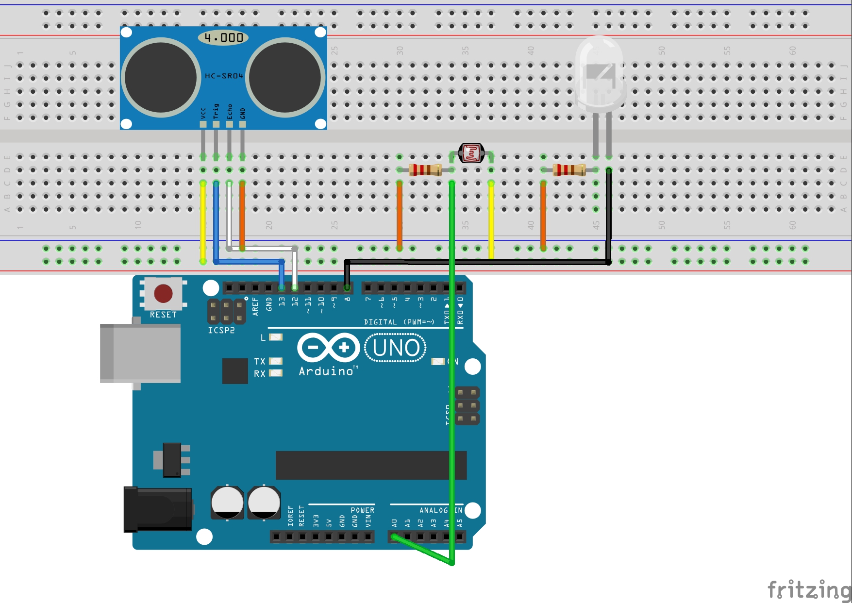
How it works
The code has an if statement that checks for two conditions- the proximity of the object from the ultrasonic sensor and the amount of light entering the photocell. Only when BOTH the conditions are satisfied, does the LED turn on. In all other cases, it remains off.
Challenges
Initially, I was having a problem with adjusting the threshold values for the two analog sensors. With the help of the serial monitor, I was able to choose the appropriate value.
Code