Week 12 assignment

After brainstorming this past week, I decided to explore my second idea in greater detail. I am excited by the prospect of using art and poetry as dynamic tools of resistance to counter biases and protest against skewed power structures.

I want to create a blackout poetry generator- which on being “fed” text can create hopeful, optimistic poetry. Blackout poetry is a genre of poetry, where removing pieces of narrative helps craft a new story.

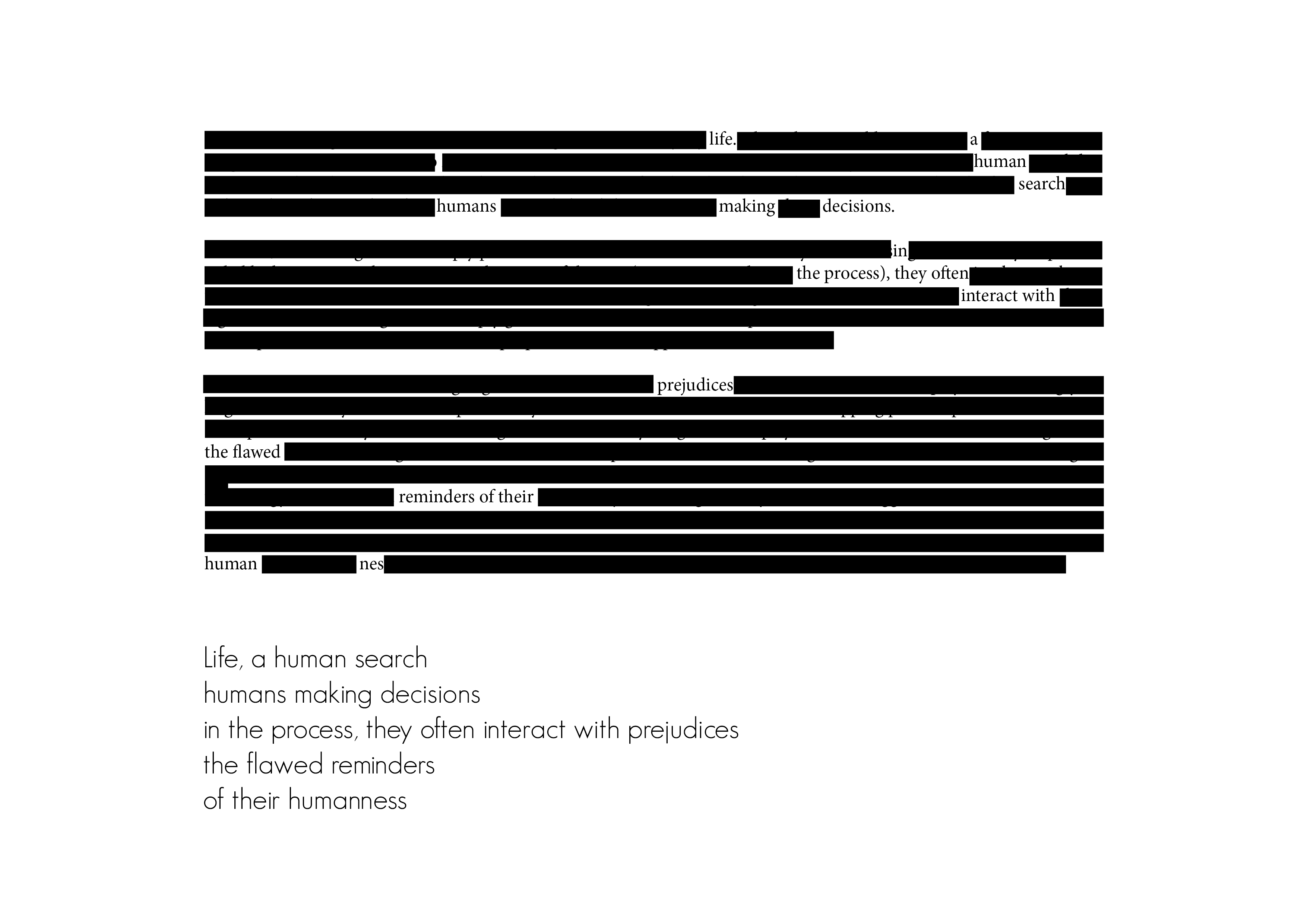
Using a tech crunch article about bias in algorithms

Using a 1973 advertisement by Donald Trump, advocating the death penalty 

Systems flow

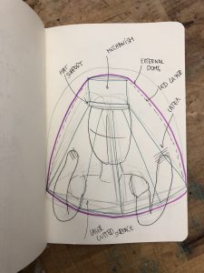
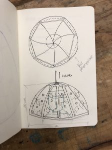
Ideally, I would like to create a program that could computationally generate meaningful poetry from the snippets of text it is provided. I was imagining a setup, where the input could be either analog (piece of paper) or digital(article), the text would be analyzed and blackout poetry generated. The challenge is then to make something that is not only grammatically but syntactically correct too.
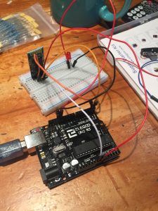
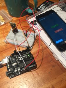
Prototype

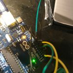
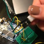
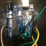
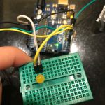
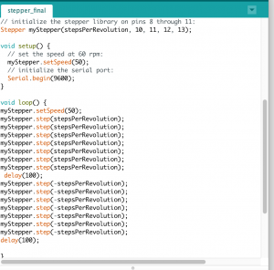
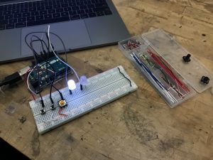
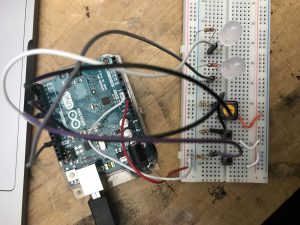
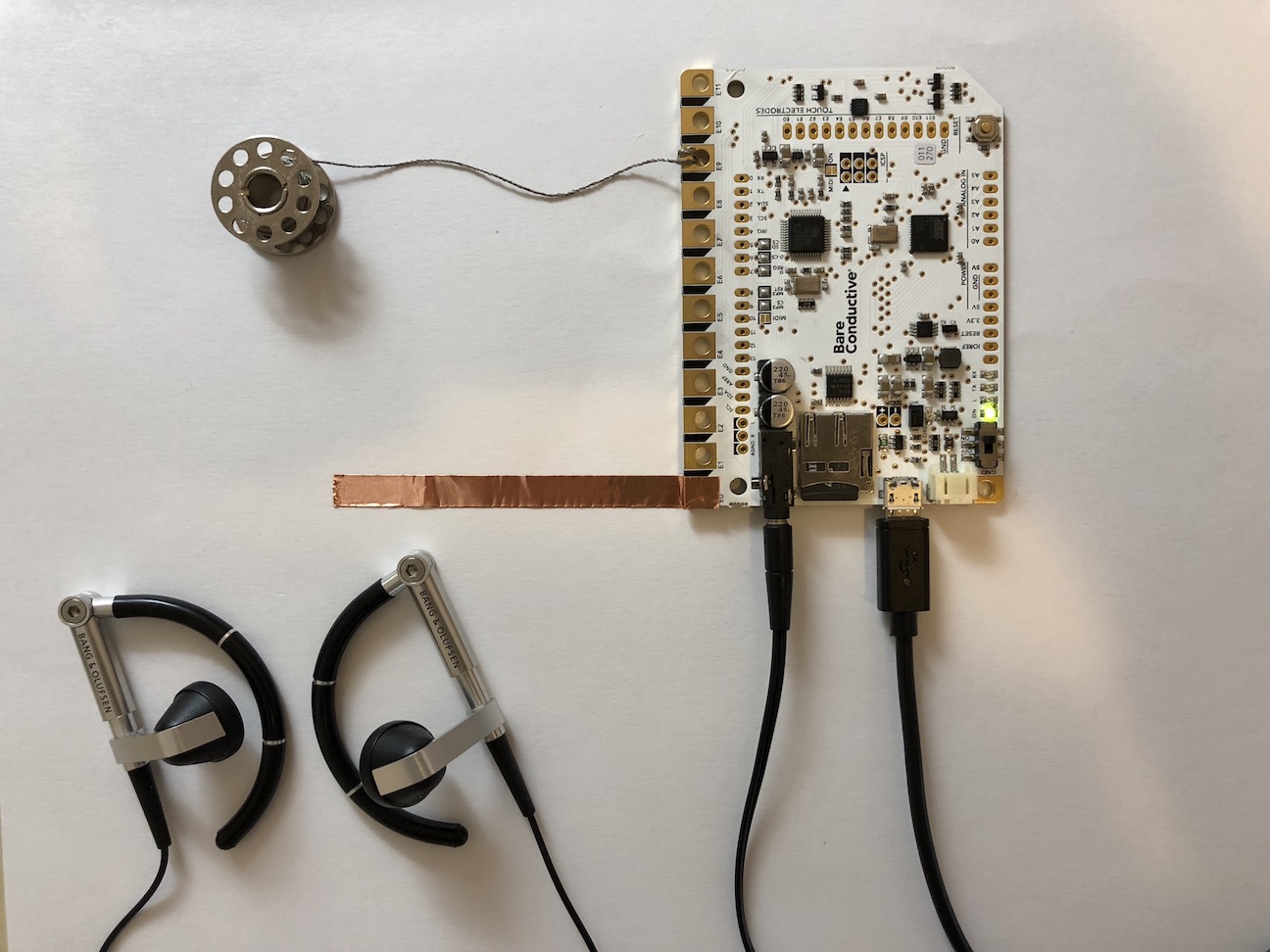
For this prototype, I decided to experiment with thermochromic pigment, which has heat sensitive compounds that change color upon reaching a certain temperature. I was working with black thermochromic pigment, which on being heated becomes clear. I tried using it with two types of glue and paint to see what would work the best. After applying the mixture to paper, I tried creating a circuit using Copper tape to heat certain portions of the text. I am unable to reach the appropriate temperature that would activate the color change.

Challenges and future iterations 

Midway through the exercise, I realized that I want the color to change from clear to black and not the other way round. I wonder if a better alternative would be to use cooling pads instead?

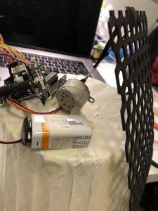
Also, I wonder if there are alternatives to using thermochromic ink- could there be a motorized system instead- which on receiving the input (the hate speech, for example), dispenses/ outputs the blackout poetry?

Play Test: Fortune Teller (Week 12)

Goal: The next part of my prototype for my fortune teller was to get the Arduino thermal printer functioning and I did. With that being said the components of just the play-test for the thermal printer include;

  • A mini thermal receipt printer – with cables and plastic mounting shims
  • A roll of 50′ long thermal receipt paper – the perfect amount for the thermal printer. BPA-free.
  • 5V 2A power supply – an ideal supply for powering the thermal printer (and anything else that can use 5V power
  • 2.1mm DC jack adapter – makes it easy to attach the power supply to the printer
  • 3x MM jumper wires

Assembling the thermal printer was a little challenging due to the site leaving out some essential pieces of information like how/where the F jumper cables for VH, GND, RX and TX are supposed to be oriented as well as the key instruction to strip the VH and GND wires to connect to the DC cable adaptor. However, lucky for me I had a friend who had experience with the Arduino thermal printer and was able to guide me through it.

Assembly:

  • Plug in the GND (black) and VH (red) F wires into the printer
    1. Cut off the open end of the Red and black wires to expose the metal inside.
  • Using the DC adaptor put in the exposed black and red end of the wires
    1. Make sure they are oriented correctly
  • Plug in the GND (black), RX (yellow) and TX (Green) wires into the printer

  • Using the 3 MM jumper wires attach them to the open end of the GND, RX and TX cord.

  • Insert the TX (green) wire into the digital ~5 pin of the Arduino

  • Insert the RX (yellow) wire into the digital ~6 pin of the Arduino

  • Insert the GND (black) wire into the GND (any of them) of the Arduino

  • Download the Thermal Printer Library
  • Change the baud rate from 19200 to 9600 by accessing the source code.
    1. If your printer test page shows ‘BAUDRATE: 9600’, you’ll need to make a small change to the library source code.
    2. Go into your computer files where the  Thermal Printer Library is being stored and using a text editor (Notepad, etc.) open the file Adafruit_Thermal.cpp
    3. Ctrl-F ‘BAUDRATE’ and change this line from 19200 to 9600.
    4. Save and exit.

Though since this code has components that conflict with my capacitive sensor code I needed to make some adjustments. I changed the RX (yellow) input pin from ~6 to ~3.

Problems/Issues: Originally when I did this (change the pin from ~6 to ~3) the LED light and the capacity was working however after I tested the printer the LED no longer responded to the capacitor. Though, as stated in the video, the LED light isn’t essential to the project it is still a sign that there might be a problem with the physical system itself. As of right now I am looking at ways to integrate the capacitive code into the thermal printer code, but as a novice in coding I’m not sure how to do this syntactically correct. I have an appointment Friday (4/20 lol.) with the Learning Center to help me over this part of the project.

Play-Test Feedback:

To think about:

  • Who will you playtest with? I will playtest with anyone who is available and willing. There is not criteria or prerequisite that needs to be met by the participants.
  • How will you get their consent? Their willingness to touch the capacitive sensor is all that is necessary.
  • What feedback do you want? I want people to experience a mediocre serendipity. It’s the equivalent to a fortune cookie so I have kind of low expectations on their reactions.
  • What questions will you ask? I will ask whether they enjoyed their fortune and if they have any ideas on how I could enhance the experience and output.
  • What information do they need to know before starting? None.
  • How much will you help them during the test? I will tell them to touch the pad.
  • How will you debrief them? I will tell them that this is my final project for a class and that is it an interactive art piece.


Thermal Printer Library

Thermal Printer

Thermal Printer Setup  

Week 7 Wireless Assignment – Lisa Ho

  • Goal of the project and/or desired interaction
    This week our homework was to choose one of the wireless topics covered in class and put it to practice for use in everyday life. I choose Bluetooth because it would be really cool to be able to communicate wireless to turn on a sensor. I decided to use Bluetooth to connect to an android phone to turn on and off an LED.
  • Quick description of assembly and list of core components
    1x Arduino
    1x Medium breadboard.1x Red LED
    1x HC 05/06 Bluetooth Module
    1x Resistors (220 ohms)
    Jump wires
    Andriod Phone

  • How it works
    The connection is simple. Only four connections to be made between Arduino and Bluetooth. After that, just connect your LED to pin 13 on one side and connect it to a 220ohms resistor.

    Arduino Pins                Bluetooth Pins
    RX (Pin 0)     ———>      TX
    TX (Pin 1)      ———>      RX
    5V                  ———>       VCC
    GND              ———>       GND

    After connecting all the wires and led, with the Bluetooth module in place, you then download an APP on the android to connect to the Bluetooth module. Then by using the LED app, you can simply turn on and off a LED with a click on the screen.

  • Any problems you encountered and/or solved
    At first, I cannot connect to the Bluetooth for the longest time. I realized the trick is not to connect the RX and TX of the Arduino pins to the TX and RX Bluetooth pins when you upload the sketch. After uploading the code and then connect these, the Bluetooth will connect fine.
  • Images of your circuit
     
  • Arduino Code
    https://github.com/lynnn43/PhysicalComputing/blob/master/bluetooth_led.ino

Week 12 – Progress

I migrated to Adafruit esp8266 module. The server now is successfully connecting to my iphone hotspot, pinging random IP numbers and when it get a success response it sends a request to a Geolocation API online service which provides the IP Geolocation information as a string of data.
What is left for the project is to edit the json data the server receives so it can easily identify the latitude and longitude coordinates and to create a light feedback. I will also create a tower design for my server.

A second stage for the project will be to create a custom laser projector that moves the laser point according to the IP coordinates. For this stage my objective is to have the relevant information to communicate to the laser.

Continue reading

WEEK 12- Technical prototype- Carla Molins

1) Iteration

For this week’s progress, I’ve been figuring out the mechanism that will power my project.

Step 1: Achieve the base system of the moving plaque.

The Arduino and the stepper motor pull the pattern and release it again. This is a rough prototype to prove that works.

This video shows how the stepper motor turns pulling for several steps until it stops and it releases again.

The next step should be trying to get a more reliable and stable prototype.

2) Your playtesting plan and desired feedback.

I’m planning on keep testing the prototype while I’m upgrading each part on D12.

There is still a lot of work to do to be able to test how the main interaction works.


Week 4

a combination lock

Understanding the basic logic behind the digital combination lock was the main goal of this project. although it seemed hardcore tech for me at first, thinking it step by step made me realize how simple it is.

Using basic components like Led, 220 ohms resistors, buttons and 10K ohms resistors,  breadboard, Arduino board, jumper wires. you can build your very own safe.

although I realized it required very basic logic, for some reason the lock could work once and stop responding after that, so I wouldn’t recommend putting your governmental papers in such a safe  🙂 so after failing hard I had to use a code from Alyssa: http://lizastark.com/physcomp/alyssas-combination-lock-week-4/ https://drive.google.com/file/d/1OlpTO_oNPYWVEbz0SmbbegJo1Oo0Lawy/view

here is some documentation starting with the failed trial and then after using Alyssa’s code:

failed

succeed

Thanks Alyssa!

Final Project Prototyping (Week 11)

  1. Testing touch board
    1. General : I tested Bare conductive’s touch board. I put different 12 drum sounds into micro SD card chip inside the board, so that each 12 nodes of the board make assigned drum sounds. I plugged in headphone to the board, and I could hear loud and clear sound from the board.
    2. Finger with direct touch : Firstly I tried to touch directly with my finger to each node.
    3. Conductive materials : I tried two conductive materials – copper tape and conductive thread. They were all successful.
    4. Distant sense (proximity) : I tested if the touch board is reacting even if it is not actually touched. It was working, but the distance has to be closer than I expected. I adjusted the value of the proximity in the code, and the maximum distance value was about 5 cm.
    5. Volume of the sound : It was adjustable in the code.

Continue reading