Final Presentation Guidelines

Woohoo! It’s finals time 🙂 Here’s everything you need to know – email me with any questions. Also, please note that last class, I said your final documentation was due the Thursday after final presentations. I have changed this to Wednesday, May 16 at midnight to ensure I get grades in on time.

DUE THURSDAY, MAY 10

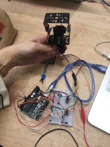
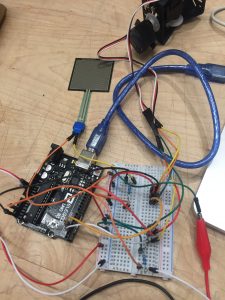
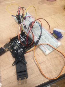
1) WORKING PROTOTYPE
You MUST bring your prototype to show – even if it is not working. If you require a specific environment, please email me.

2) PRESENTATION
You will have 8 minutes to present. This includes time for feedback, so structure your presentation accordingly. Your should include the following in your presentation ( in whatever order you like):

  • Problem statement + design goals
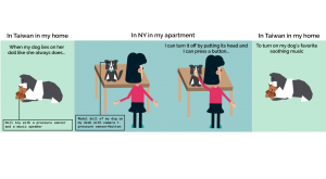
  • Concept
  • Precedents
  • Project demo or video of project demo
  • Playtesting + feedback
  • Process documentation
  • Challenges you faced
  • Future iterations

3) VIDEO DOCUMENTATION
You should make a short video introducing your project. It should include the title of your piece, your concept, and a prototype demo.

DUE WEDNESDAY, MAY 16 AT MIDNIGHT (I will not accept late submissions)

1) BLOG POST

  • Create a blog post that documents your final project. It should include:
    • Your presentation
    • Concept + Goals. What is your concept? What were your goals? Why did you decide on this project form for your concept and goal?
    • Intended audience. Who is this for? Why did you choose this audience?
    • Precedents. Share any precedents that inspired you.
    • Description of the project. Discuss the process of creating this project. How does it work? What is the desired interaction?
    • Video documentation. Include the video described above.
    • Materials list. List the materials you used and link to where people can purchase.
    • Process + Prototypes. Discuss the process of creating this project. Show your prototypes, playtests, sketches, interaction diagrams, and any other files that illustrate the tools you used. What challenges did you faced? What would you do in a future iteration?
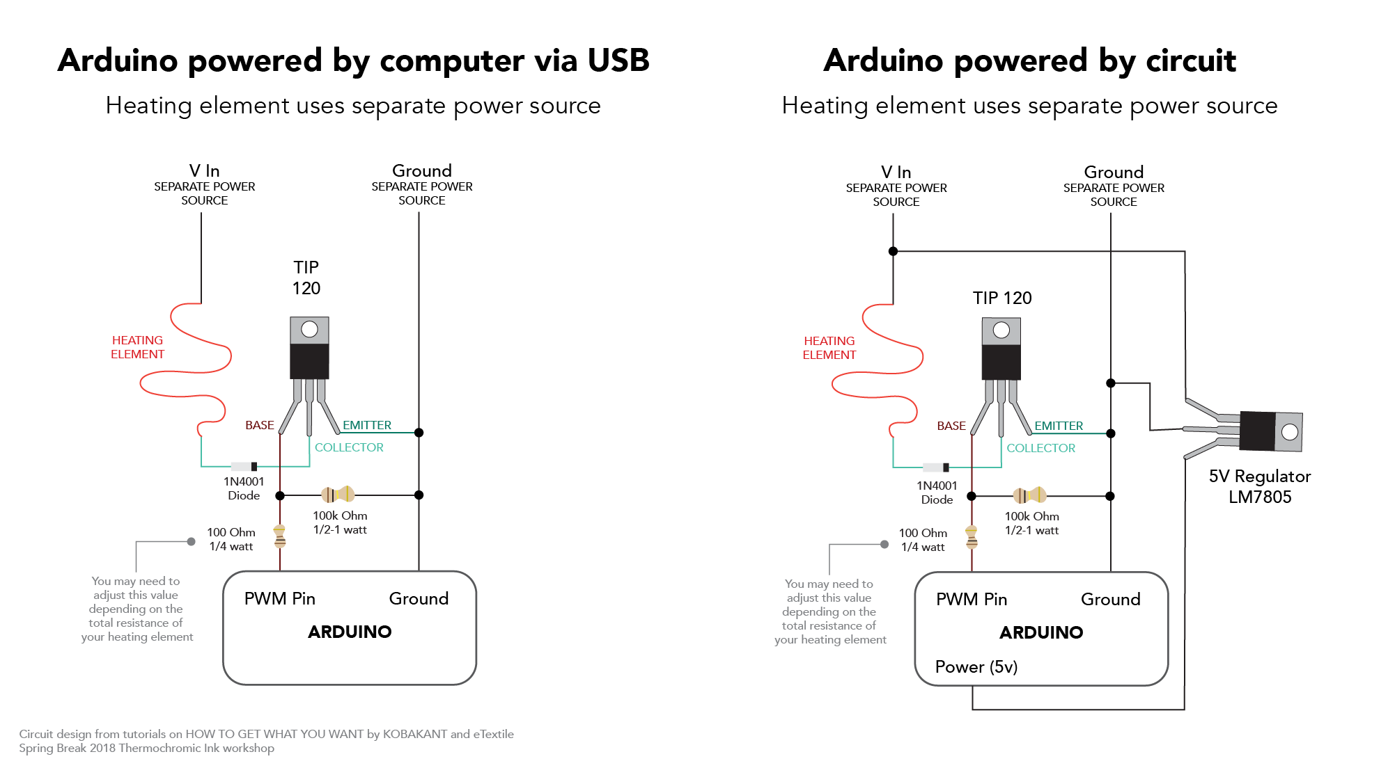
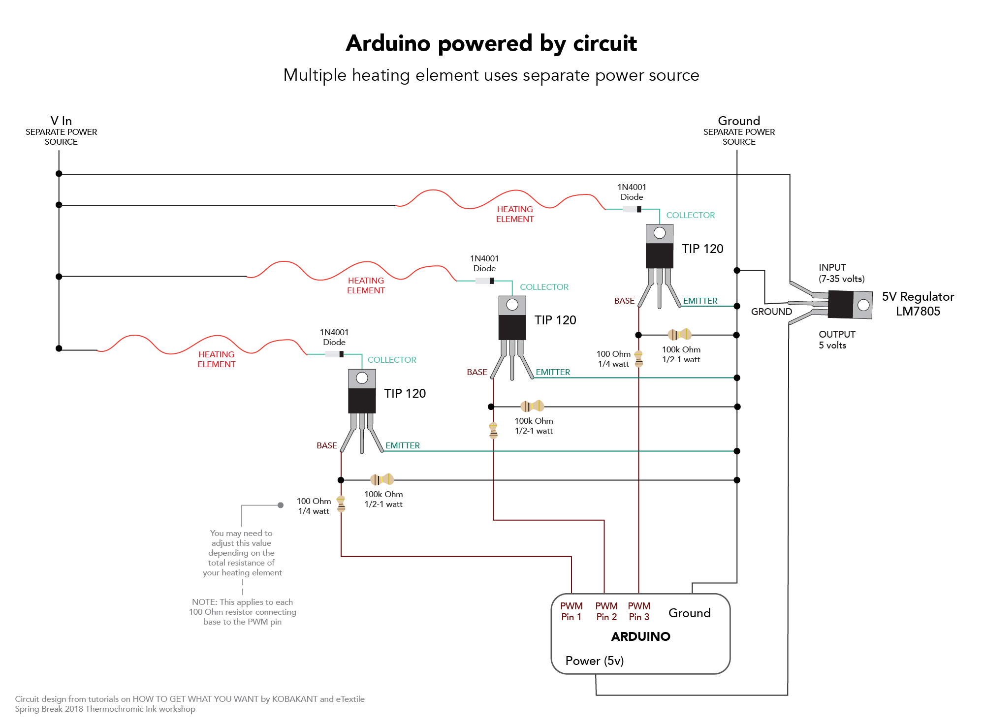
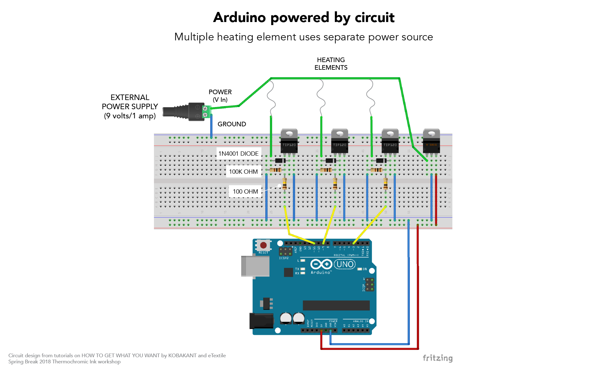
    • Circuit diagram. Be sure to include a circuit diagram or drawing. Be specific and detailed.

ASSESSMENT GUIDELINES

I will assess your project by the following criteria:

Ideation, Concept, and Design

  • Demonstrates a strong conceptual foundation and clearly stated design goals
  • Clearly articulates audience
  • Able to translate ideas/concepts into project form within a given environment
  • Thoughtful integration of design elements
  • Presents functioning, high fidelity prototype or working documentation if was unable to get working
  • Does not use breadboard for circuit housing
  • Synthesizes design and technology to create interesting and contextually significant work that makes contributions to the domain

Process + Materials

  • Thoroughly documented according to class guidelines
  • Uses materials, tools, and processes learned in class
  • Iterated prototypes
  • Demonstrated effective problem-solving/ finding skills

Presentation

  • Articulated concept and problem statement clearly
  • Prepared for presentation (slides ready and prototype set up)
  • Addresses all required elements for presentation as described above
  • Stays within presentation timeframe (8 minutes)

Heating Circuits

For those of you interested in heating circuits and thermochromic ink, below are some helpful circuit configurations. These circuits were taken from the Building Heat Controlling Circuit workshop at eTextile Summer Camp, KOBAKANT’s How to Get What You Want site, and the thermochromic ink workshop at eTextile Spring Break. Please see these links for a deeper explanation on different types of heating elements and power sources:

This uses a TIP 120 but you can also use a Mosfet IRLZ34N SPBF (they have the same pinout).

More on transistors here and here:

heating_circuit_1

Week 12 Documentation – Final

 1. 2nd Iteration of My Prototype

  • Goal of the project and/or desired interaction
    I hope to be able to press on a force pressure sensor to activate the camera for the face detection to track my motion and then turn the camera off by pressing on another force pressure.
  • Quick description of assembly and list of core components
    – Arduino x1
    – Small Bread board x1
    – Force pressure sensors x2
    – Servo motor x2
    – Jumper wires
    – Resistors 220ohm x2
  • How it works
    When you stand in front of the camera, it will not work but when you press on 1st pressure sensor, the camera will start tracking your motion and turn towards wherever you are moving. You can turn the camera off by pressing on the 2nd pressure button.
  • Any problems you encountered and/or solved
    I have encountered many problems with the code where the code tends to be stuck in an IF statement and another problem I still face is that the code only runs once. After running once, it won’t activate again unless I restart the Arduino and processing sketch again. I still haven’t figured out what is the problem since the code looks all correct.
  • Images of your circuit
  • Processing/Arduino Code
    https://github.com/lynnn43/PhysicalComputing/blob/master/SerialServoSketch.ino
    https://github.com/lynnn43/PhysicalComputing/tree/master/LisaPanTiltFace_1


2.  Your playtesting plan and desired feedback

Who will you playtest with?
I will playtest with my fellow peers from Design & Technology program and possibly some other same age peers from different programs in Parsons.

How will you get their consent?
I will ask them if they are willing to test out a quick interaction and give me some feedback.

What feedback do you want?
I want the interaction of my model doll dog to be intuitive so I know where to exactly design my pressure sensor on my model dog.

What questions will you ask?
What is the first intuitive response of placing your hand at (on my model doll dog)?
Where do you think you can press to activate music?

What information do they need to know before starting?
I will give them a basic overview of my concept.

How much will you help them during the test?
Aside from trying to give them a basic overview, I will try to let them figure out themselves. If they really need help, I will give them hints.

How will you debrief them?
I will let them know what I’m really testing orally and ask them if they have any questions.

Continue reading

Week 10 Assignment -Final


Continue reading

Fortune Teller (Week 13)

Goal: The goal of this project, to create the fortune teller using an arduino, thermal printer and capacitive sensor is still the same. The last time I posted I had achieve connecting the capacitive sensor and the printer into a single code. However, I still had no been able to figure out how to get the printer to print is accordance to when the capacity passes the 1000 point threshold, or in other words, when the capacity is touched. Ergo, for this past week my 3 major goals/ obstacles to overcome.

  1. Figure out how to have the printer read and print according to when the capacitive sensor is touched.
  2. Code the arduino to be able to read the capacity and give fortune according to different ranges in the capacity. For example; 1000-1499 (“The world is your oyster”) and also be able to code for if the capacity read is even or odd for another layer of fortune telling.
  3. Have the printer print the fortune.

Assembly: So I made two appointments (knowing that I probably wouldn’t complete this in one day) at the Learning Center. Originally I was trying to connect the printer to print in accordance to the push of a button, but Tubah and I had a lot of difficulties with the button so we jumped straight into using capacity. Eventually by the end of the session we got it connected. However, the printer was unable to print the correct symbols (we were testing with a barcode) matter of fact it was printing an infinite series of illegible symbols. So with task #1 taken off the list I had simultaneously created 3 more.

I was able to conclude from my experience with the Serial monitor that a possible cause of the symbol affliction was due to baud-rate and or Arduino syntax between softwareserial/ mySerial.begin and Serial.begin. I also would have to code a way to make the Arduino read the first number of capacity and then pause so that it wasn’t continuously printing fortunes for the milliseconds a participant may be touching the capacitor. Lastly, the serial monitor was no longer printing the read capacity. I wanted to be able to see the capacity change on the serial monitor so that I could make capacity ranges for fortunes.

  1. Find out how to get the printer and the Arduino speaking the same language.
  2. Code the arduino to be able to read the capacity and give fortune according to different ranges in the capacity.
  3. Code the Arduino to read only the first number of capacity past the threshold and then sleep.
  4. Get the serial monitor to print the capacity
  5. Have the printer print the fortune.

The following Monday I met with another tutor at the Learning Center, Aarati. She was amazing and helped me find the problems in my code. My intuition was right, the baudrate for the printer was changed from 9600 to 19200, which allowed the printer to be able to read the code and print correctly. Tangent from this, with small changes to the syntax of the code we were able to get the Arduino and the serial monitor to connect on the right level, thus presenting the capacity in the monitor. Lastly we even finished early enough to add in an “odd and even” if-else statement to the fortune code allowing for if the capacity if even an “evil fortune” if the capacity is odd a “nicer fortune.”  

How it works:

This is intro code to how the Fortune Teller tells it fortune. By defining several specific ranges of capacity I am able to tell the printer to print an according fortune.

The ranges I have thus far:

Capacity >= 1999 — Fortune
Capacity >= 1750 — Fortune
Capacity >=1499 — Fortune
Capacity >=1250 — Fortune
Capacity >= 1000 — Fortune
Capacity == 666 — Fortune

Materials:

  • A mini thermal receipt printer – with cables and plastic mounting shims
  • A roll of 50′ long thermal receipt paper – the perfect amount for the thermal printer. BPA-free.
  • 5V 2A power supply – an ideal supply for powering the thermal printer (and anything else that can use 5V power
  • 2.1mm DC jack adapter – makes it easy to attach the power supply to the printer
  • 6x MM jumper wires –
  • 1x LED
  • High Powered Resistor

My next step of this process is now to construct the the fortune Teller itself, solder a new clean board and clean the code up a little.

Some of my new goals are:
1) Find a way to add a text box around the code
2) Possibly make the presentation of the fortune a little more aesthetic
3) Build a nice sturdy stand to hold to box up right.
4) Make a robe and hand.

Thermal Printer Library

Thermal Printer

Thermal Printer Setup  

  • Assembly:
  • Plug in the GND (black) and VH (red) F wires into the printer
    Cut off the open end of the Red and black wires to expose the metal inside.
    Using the DC adaptor put in the exposed black and red end of the wires
    Make sure they are oriented correctly
    Plug in the GND (black), RX (yellow) and TX (Green) wires into the printer
  • Using the 3 MM jumper wires attach them to the open end of the GND, RX and TX cord.
  • Insert the TX (green) wire into the digital ~5 pin of the Arduino
  • Insert the RX (yellow) wire into the digital ~6 pin of the Arduino
  • Insert the GND (black) wire into the GND (any of them) of the Arduino
  • Highest Resistor (150.5K) ~4pin and ~8pin
  • Power Cable LED ~7pin
  • Ground Cable LED GND.
  • Download the Thermal Printer Library
    Change the baud rate from 19200 to 9600 by accessing the source code.
    If your printer test page shows ‘BAUDRATE: 9600’, you’ll need to make a small change to the library source code.
    Go into your computer files where the  Thermal Printer Library is being stored and using a text editor (Notepad, etc.) open the file Adafruit_Thermal.cpp
    Ctrl-F ‘BAUDRATE’ and change this line from 19200 to 9600.
    Save and exit.

Week 12

in this stage of the process, I started to think of the UX part. I started by deciding to add a touchscreen to the camera. and thinking about making it work independently.  but after meeting Liza, I’m reconsidering adding a button which was the initial idea. connecting both cameras through one conductive button that takes both digital and analog images.

Prototypes – DarioN (Week 12)


Goal:

In this phase of the project, various technical approaches were considering as methods to resemble the light emitted by a firefly in a jar.

The first explored technology was a matrix of LED’s – Charlieplex-, which consisted in making a cloud of LEDs (soldering one by one) until achieving the desired lighting effect. This matrix was discarded since it requires a lot of space for wiring and hardware (hard-points), besides it is complex to test-build in the desired final object.

Fiber optic was another technology tested to make the effect of fireflies flying in a jar. This was not a good direction since the intensity of the light was not enough and it also required a matrix of complex LEDs on the base of the object. This image shows an exploration using acrylic rods sandblasted on the tips, to work as a fiber optic. A series of LED transmit light from the bottom of the rod.

Lasers, projectors and a mechanical system were other alternatives that were evaluated, but finally the programmable LED’s strip get the desired effect with the variations of speed and tonality of the light. In this option there is an important challenge, since the programmable LEDs require a lot of current, so a very large battery pack is needed, and this must be assembled inside the artifact without breaking its form and optimal operation. One of the requirements is to avoid using cables and power supply connected to a wall, since this would drastically affect the experience.

List of Components:

  • x1 Arduino Uno
  • x1 Breadboard
  • x1 Adafruit Neopixel 144 RGB LED Strip
  • x1 330kohm Resistor
  • Jumper Wires​

Assembly Process:

To create this prototype, I connected the Strip to the 5V of the Arduino and to the digital pin 6. Since I was planning to turn on 6 LEDs and not the whole strip, I was OK with the current provided by the computer (in this case). For the final product, I must consider the number of LEDs that are going to be on and the amount of current needed. If I would like to use all the LEDs in full white brightness, I would need around 9A to hold the whole strip. Each LED runs with around 60mA.

User Testing:

The objectives in this phase are raised from the observation of children and adults catching fireflies supported in a ‘playful’ context, and different ways in which they caught fireflies should be analyzed. The other important objective is to understand how users  interact with an artifact that has no instructions, is it intuitive to use? is it too complex? why?.

In summary, in the process of catching fireflies can be identified 3 different paths.

Using the hands: Although it takes many attempts, this is a common way to catch fireflies, since it is relatively easy to catch them. For the specific development of the project, this method of catching fireflies is not the most appropriate, since an external artifact (sensor) is required and together with this a complex system that affects the simple and intuitive nature of the experience.

Using a net: Like the previous one, this is a very common and simple way to catch fireflies. This method would consist of two systems (a net -to catch- and a container -to keep the fireflies-) complex both technically and objectively, since simultaneous work is required for the experience.

Using a container: In this method the net method is basically used as the previous one, where the fireflies are trapped directly with the container so as not to let them escape. This way of catching fireflies is what most resembles the product you want to finally reach; because it is an experience with the product as such (the product is experience). It is a way that finally does not add complexity to the final product because it has no external systems, and also intuitively communicates the objective of the product in its entirety. It is important to clarify that, like any product, instructions are required, which in this particular case, was developed in the form of a story book as a sub-artifact inspired by nostalgia and memory.

References:

https://github.com/technobly/NeoPixel-KnightRider

https://learn.adafruit.com/adafruit-neopixel-uberguide/the-magic-of-neopixels


Week 11 – Xiaoyu & Weilin

We have tested several materials and components.


Input: Velostat (Pressure sensor) + conductive tape

Output: audios represented different moods

Chairs also have work hours. They are happy to assist you during work hours but they can also get crappy sometimes. They also preserve the right to refuse anyone when they are on a break.