PART 1
Goal of the Project:
The intention with this project was to explore the infinite creative possibilities of playing with the relations between light and sound using a microcontroller. In this particular case, I wanted to explore new sensors such as BIG sound as input that triggers other process such as turning on and LED.
List of Components:
- x1 Arduino Uno
- x1 Breadboard
- x1 Big sound module
- x1 RED LED
- x1 220 kohm Resistors
- Jumper Wires
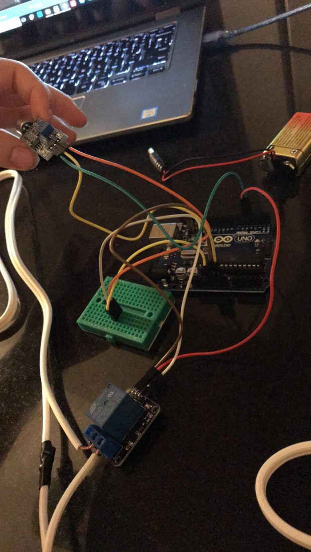
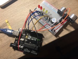
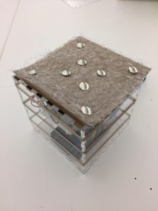
Assembly Process:
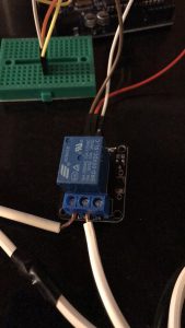
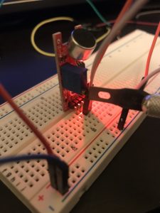
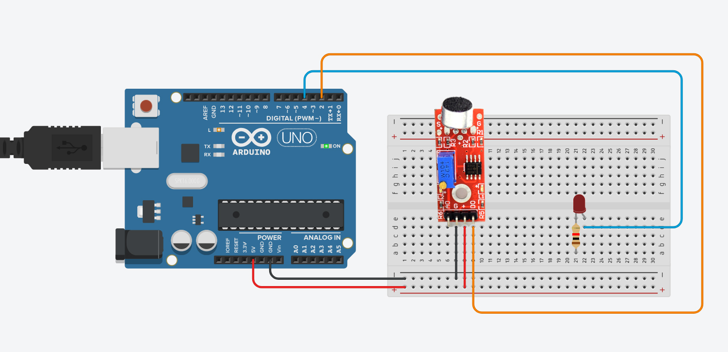
To create this project, first, the big sound module has to be connected to Arduino (We can use a Digital pin or Analog Pin. In this case, we used the digital pin 3, but we need to tell Arduino we are using it as DIGITAL input). Then we connect the LED to a digital pin 4 as an OUTPUT.
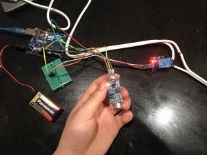
How it works:
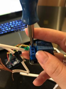
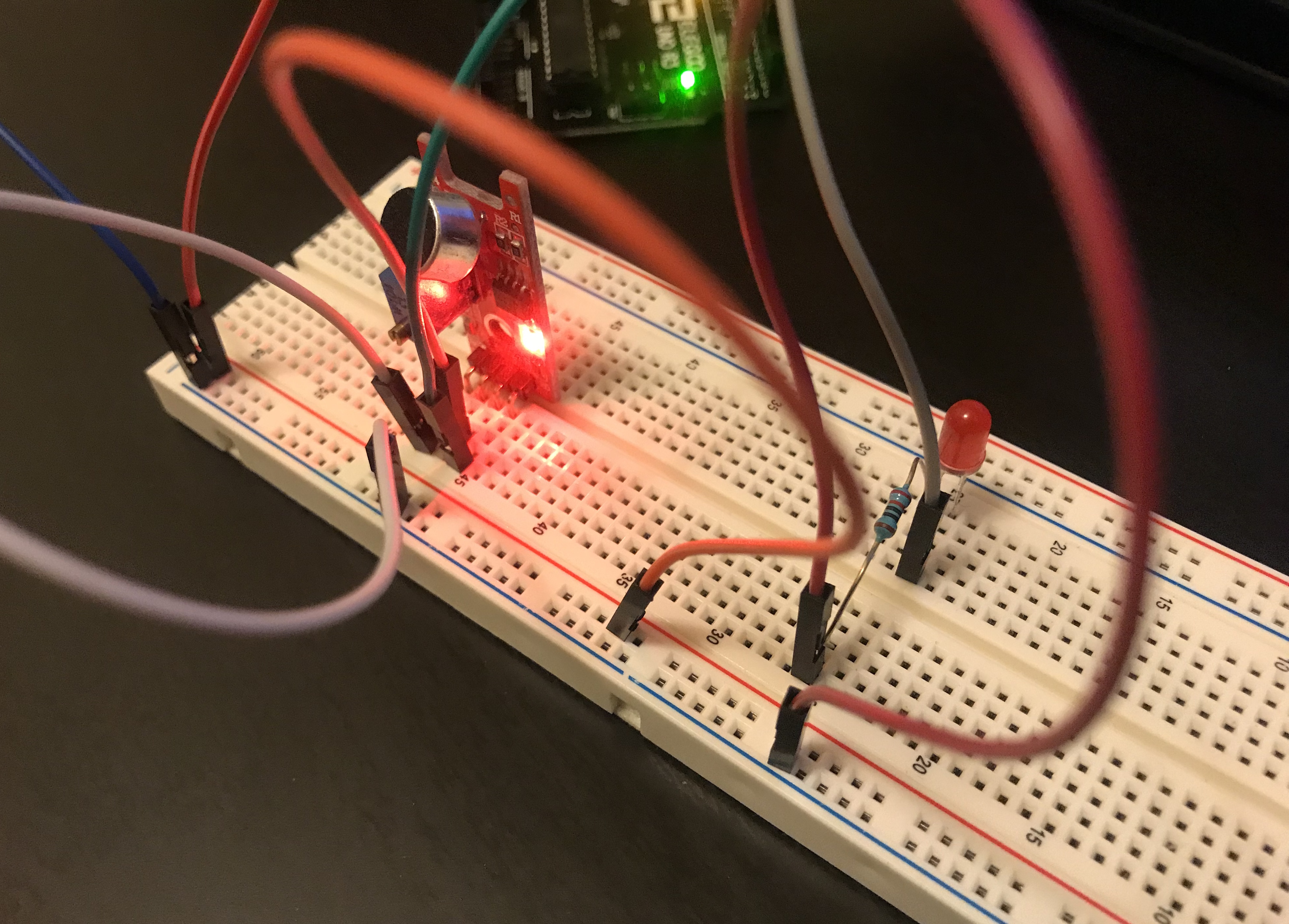
To test the Big sound module, the 2 LEDs of the module will light up. In order to control the sensibility of the module, we need to move the built-in potentiometer in the module using a screwdriver. The idea is to turn it to the left to reduce resistance and add sensibility. As soon as the led turn off, that means the module is ready. Then we connect an LED to a pin and set it as OUTPUT. The result? The LED will respond to the high and low frequencies received from the sounds from the surroundings.
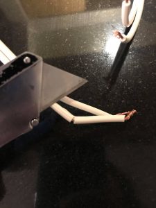
Problems:
Controlling the sensibility of the bid sound module represented a challenge. I wasn’t able to get an important sensibility value in order to control the LED. To test it, I had to create sounds with deep basses and had to be fairly loud. I also test the “small sound” module and the issue was even worst.
Arduino Code (File):
https://www.dropbox.com/s/rgi5s89rif0mg1b/DarioNarvaez_HW6.ino?dl=0
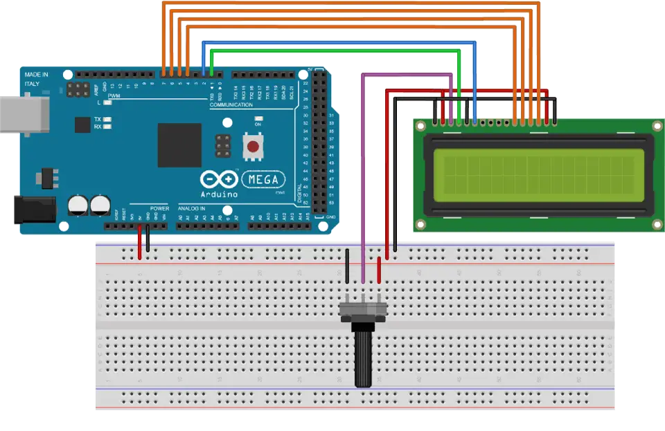
Circuit Diagrams:
References:
https://create.arduino.cc/projecthub/iotboys/control-led-by-clap-using-arduino-and-sound-sensor-e31809
PART 2
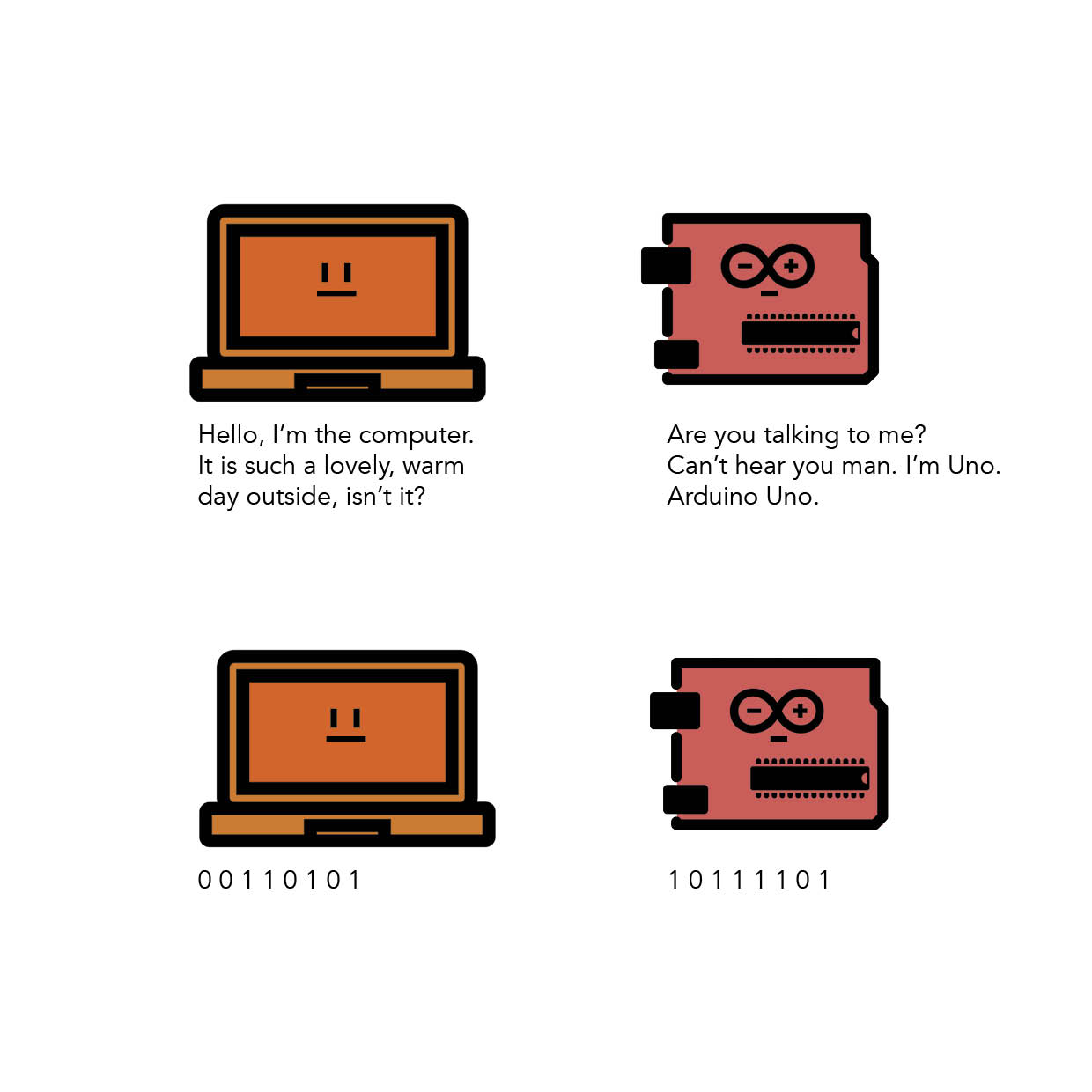
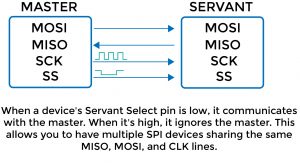
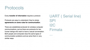
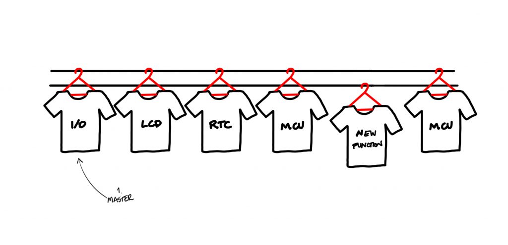
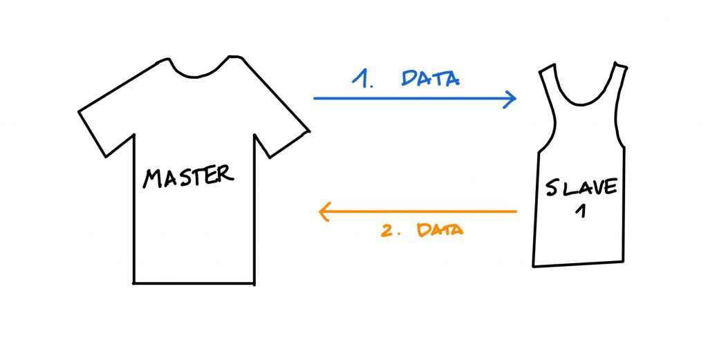
I2C Protocol:
Or Inter-Integrated Circuit is a protocol that allows to connect multiple “slave” devices to a one “master” device. It’s the most used between electronic devices (microcontrollers, sensors…cellphones, cars…). The connection between a microcontroller (Arduino) with sensors and modules are good exaples of Master-Slave relation, where both can communicate to each other, but the communication is initiated only by the master.
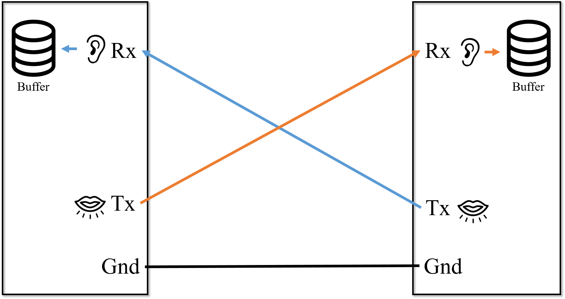
Pros:
Only requires 2 wires that can support multiple devices for the communication (bus connection) up to 127 devices.
Simple to use, reliable and inexpensive.
Cons:
Short distance communication with a single device
Hardware is more complex than other protocols
Resource: