Goal of this project : I would like to make a sample version of TV’s display of indicating channels and volume and remote control. Using IR receiver module and remote control, it will enable users to control channels (number) and volume (up and down).
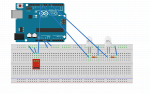
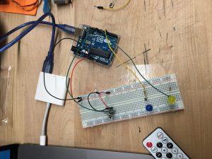
Assembly description : I made a circuit that IR receiver module and 7-segment display to be connected to the arduino uno. IR receiver module has three legs – one (G) is for ground, the other one (R) is for Vcc, and the last one (S) is for signal. I connected the signal pin to pin 11, and set an additional led in pin 13 so that user could know the signal is receiving or not (We could also know through the tiny light on IR receiver module). For 7-segment display, the each pin represents each different stroke that constitute a number (including period “.” to confirm the exact direction of numbers). It has total 10 pins, 8 of them representing strokes are connected to each different output pins, and two of them are connected to the ground.
Anode to 5V If Strip Gnd of driver to gnd of Arduino
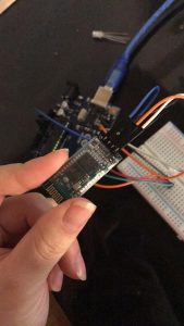
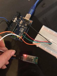
Blue Tooth Connection to Arduino:
Rx to pin 12 of Arduino
Tx to pin 11 of Arduino
vcc to 5v
gnd to gnd
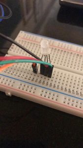
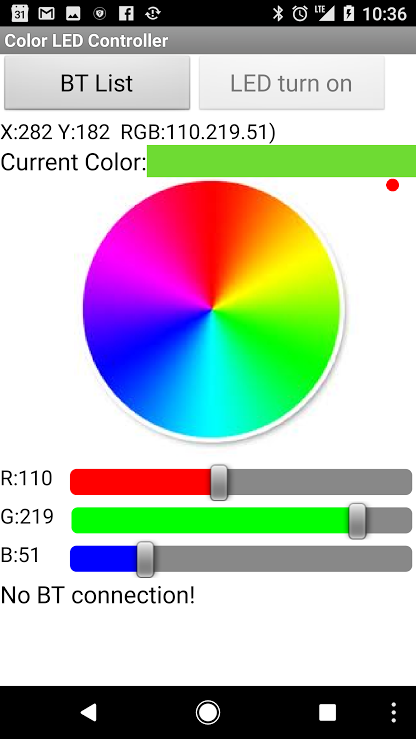
How it works: As the concept goes, via bluetooth and the correct smartphone app I will be able to control the color of the LED wirelessly. The designer of this project went into depth about the logistics of how the RGB LED actually changes colors by describing how the Arduino uses a digital representing Analog signal that varies pulse to mimic a PWM (Pulse Width Modulation). By using a digital representing Analog signal the colors are able to seem like they are gradually changing even when they are not.
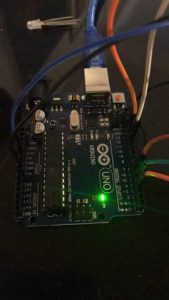
Problems: I faced a plethora of problems with this assignment. From jumping to project to project trying to find a source that didn’t rely on Android applications or Google Play to simply the code refusing to upload onto the Arduino “programmer not responding.” To say the least I had many difficulties. Though I believe the most prevalent can be found in the fact the alternative applications I downloaded onto my phone (Iphone) to control the LED via blue tooth could not connect. I’m not sure if it was because of the code/ Arduino blue tooth or the app not being compatible with the program, regardless it didn’t work. I ended up accidentally burning out my RGB LED, so I will try again tomorrow with another application!
I want to control the light in different rooms.
Use IR sensor to control the brightness of LED, and turn on/off of LED
Core components
1* IR sensor
1* remote control
2* LED
2 * 220 ohms resistors
Wires & jumpwires
Arduino board
Circuit/Schematics
How it works
Button 1 : switch on/off of blue LED
Button 2 : switch on/off of yellow LED
Button + : increase brightness (++ 50)
Button – : decrease brightness (- – 50)
Two LEDs have different on/off state, but have the same brightness.
Problems
Two LEDs can’t be adjusted separately
The remote control is inaccurate
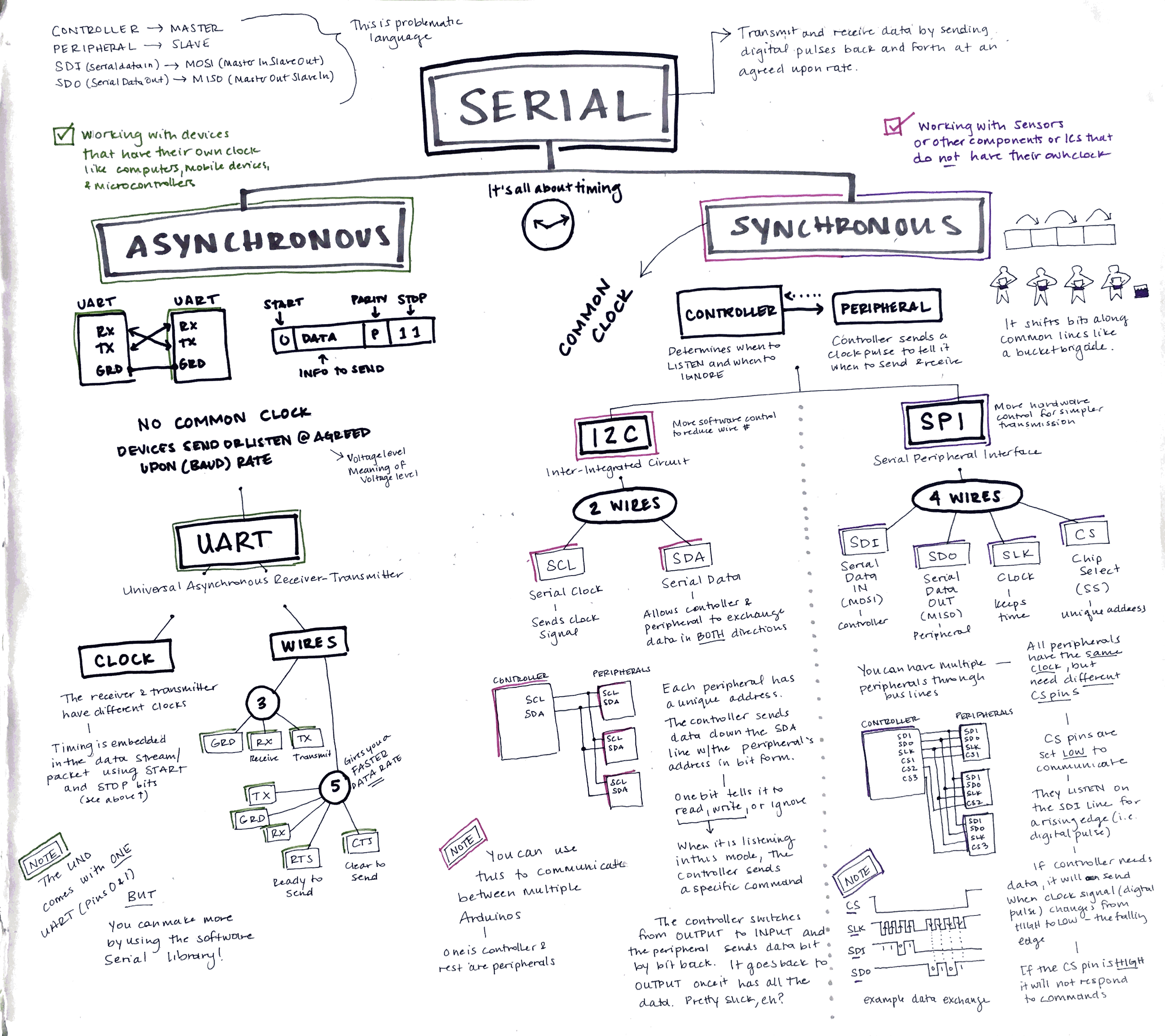
Communication is asynchronous, meaning it does not depend on a synchronized clock signal between the two devices. You can set the data transfer speed and format as needed — you basically set an agreed-upon timing between the two devices.
Choose one of the wireless topics covered in class and put it to practice for use in everyday life. For example, use the IR sensor with a remote control to make a fan for a hot summer day.
Document your project in action and post to the class blog, including the list of materials used, a circuit schematic, and notes regarding wins and challenges.
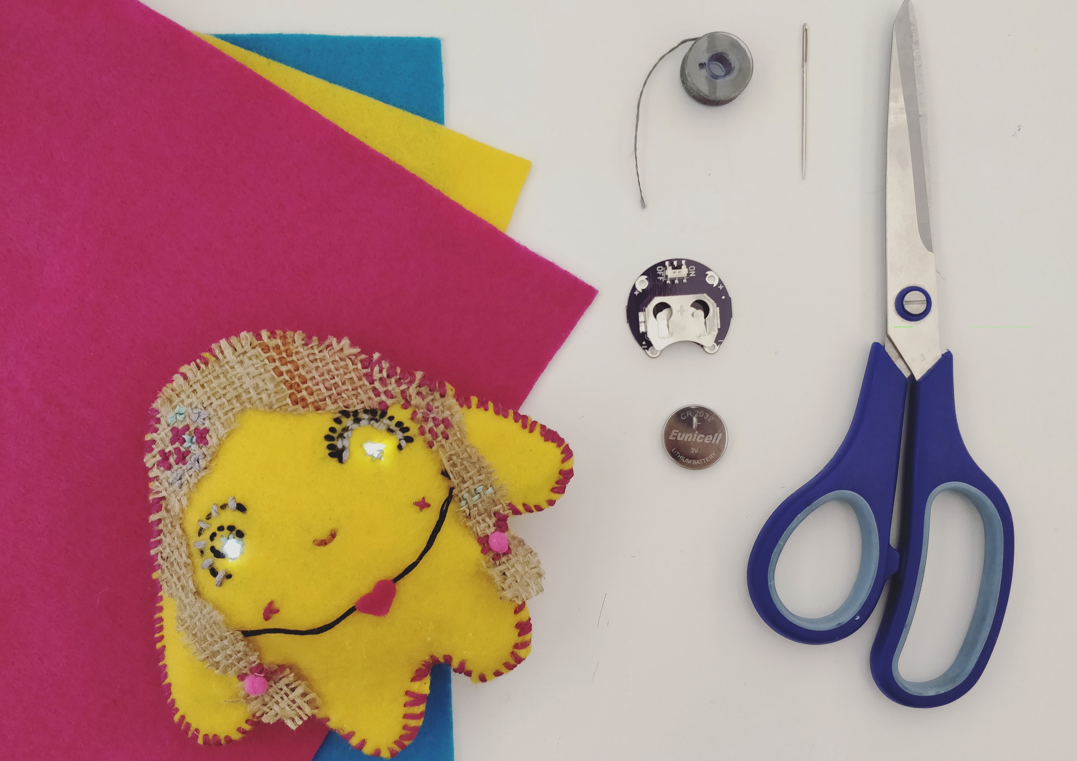
For a very long time, I have been fascinated by e-textiles because they lie at the intersection of craft and electronics. I did not know where to begin my exploration from and decided to follow along a simple Sparkfun tutorial to make a light-up plush (https://learn.sparkfun.com/tutorials/light-up-plush)
Materials required
Lilypad ProtoSnap
3V Coin Cell Battery
Conductive thread
Needle
Plush pattern
Felt piece: 10 by 10 inches
Scissors
Fabric glue (optional)
Beads, pompoms, ribbons, buttons, glitter to decorate
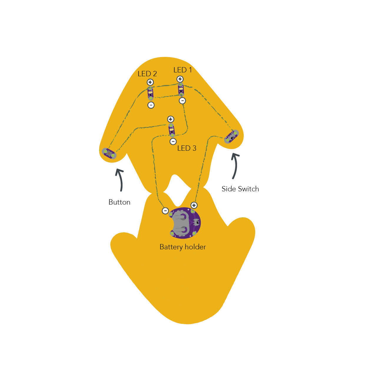
Diagram (taken from the Sparkfun website)
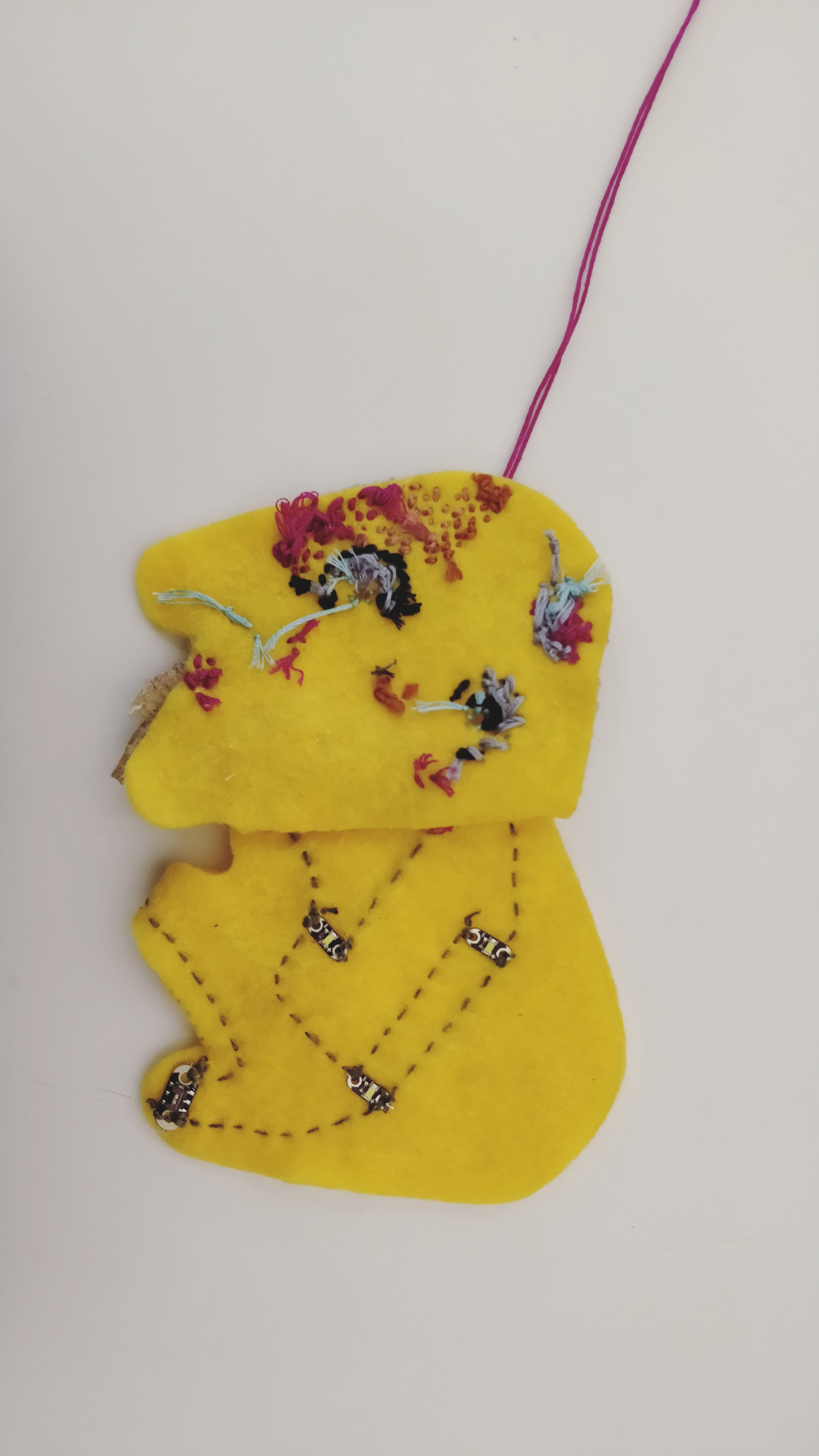
Description of assembly
Cut the plush pattern from the piece of felt
Arrange the Lilypad ProtoSnap components on the pattern.
Using conductive thread, make secure connections (loop around each tab at least 3-4 times) between the positive tab of the battery holder and one of the tabs of the switch.
Connect the other side of the switch to the positive terminals of the top two LEDs that make up the eyes, and finally to one of the tabs of the button.
Continue stitching, from the other side of the button to the positive tab of the last LED.
Connect the negative sew tab of the first LED, with the second, through the third to the negative sew tab of the battery holder.
Insert the battery, debug, and keep experimenting!
How it works
I was surprised to find that working with e-textiles isn’t very different from working with the Arduino hardware. It is based on the same principles of electronics that we are familiar with. A 3V coin cell powers the circuit, and the electrons, regulated through the side switch and the button, light up the LEDs.
Challenges
I had difficulty debugging my circuit. Unlike a “traditional” circuit, it was time-consuming to check the connections- as I had to re-embroider entire sections. Later I realized, that my circuit was getting shorted because of the long, untrimmed pieces of wire. After securing a few connections, and trimming the ends, it started working!
Future Iterations
I am excited about incorporating physical elements or characters in the process of digital storytelling. I feel they make the story more compelling. I was imagining a choose-your-own-adventure story, that plays out on the screen, depending on one’s choices in the real world. So these characters could act as controllers that are affecting the narrative. Continue reading →
Choose one of the wireless topics covered in class and put it to practice for use in everyday life. For example, use the IR sensor with a remote control to make a fan for a hot summer day.
Document your project in action and post to the class blog, including the list of materials used, a circuit schematic, and notes regarding wins and challenges.