Week 10: Final Project Planning
Leave a reply
This week’s assignment was to creatively rethink how sound and/or light could be incorporated into projects by modifying the input sensors. I decided to work with capacitive sensing because I love the possibilities it provides. It allows us to make our own sensors and enhances the quality of the interactive experience.
List of Materials
1 x Elegoo Uno R3
1 x Full sized breadboard
1 x Piezo buzzer
3 x Graphite strips
3 x LEDs
Resistors: 3x 220 Ohms (for the LED), 3 x 1 Megaohms (for capacitive sensing)
Jumper wires
Fritzing diagram
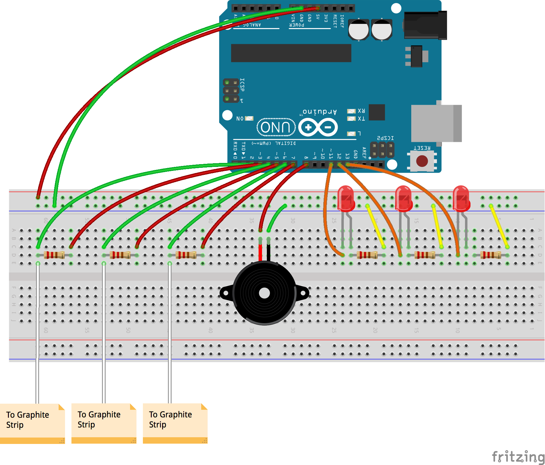
Description of assembly
How it works
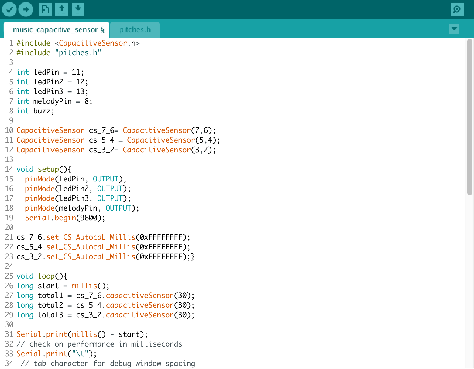
Capacitive sensing works on the principle of using a conductive material to complete the circuit. This circuit works as follows. A high resistance of the order of a megaohm is placed on the breadboard, both ends of which are connected to say, digital pins 2 and 3. Digital pin 3 acts as the input and allows a steady stream of electrons to flow through the circuit. The resistor inhibits the flow and only lets a small number of electrons pass through the other end. The other end in addition to being connected to a digital pin is also attached to a jumper wire. When we touch the metallic end, we pass on a large number of electrons from our body to the circuit. The Arduino can sense this change and can be coded to control an output by defining a threshold value.
Iterations
Graphite conducts electricity and this property can be utilized in interesting ways. I shaded some bits of paper with an HB pencil and connected them to the breadboard so that they could act as switches. For the first iteration I decided to make an instrument where, on pressing each key, one would hear a different, pre-programmed song through the Piezo buzzer. I first tried with the example code melody to see whether all three switches were working individually. On graduating to coding different songs, I had limited success.
This further led me to think about how a user could make their own music. On pressing a key, they would hear a tone, akin to a piano. The various sequences and combinations could culminate in unique tunes. I had trouble associating one LED to one graphite switch. After multiple iterations, it turned out to be a glitch in the code which I then rectified.
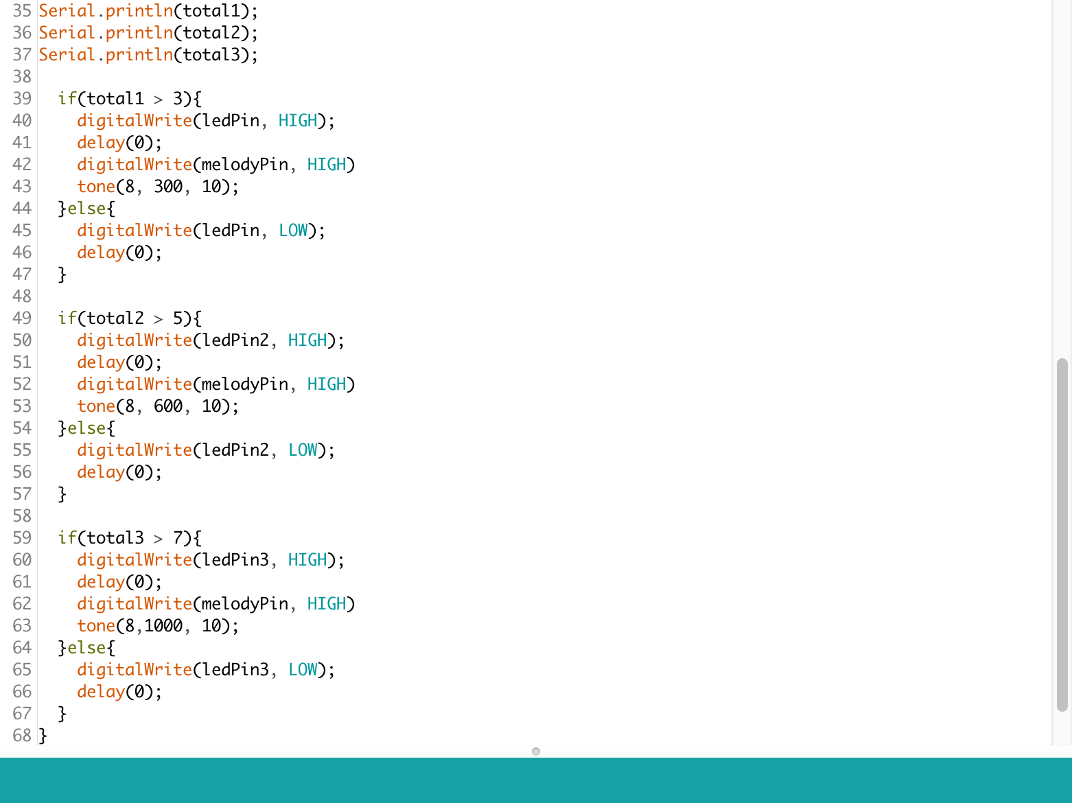
Code
Goal of the Project:
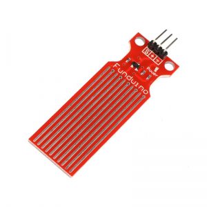
With this project, I wanted to explore a new and rare sensor as a trigger/switch for a stepper motor. In this case, I used a ‘Water Level Sensor’ to tell the Motor when to turn on and off depending on how deep the sensor was into the water. I wanted to challenge myself into going to use new tools and hardware.
List of Components:
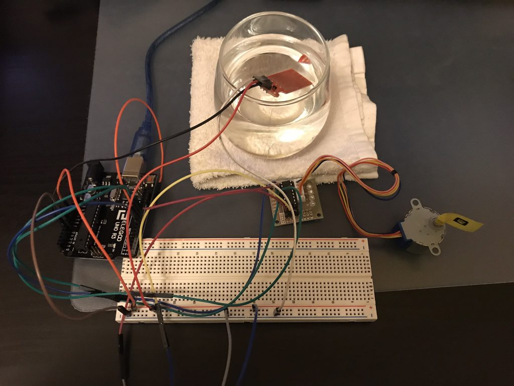
Assembly Process:
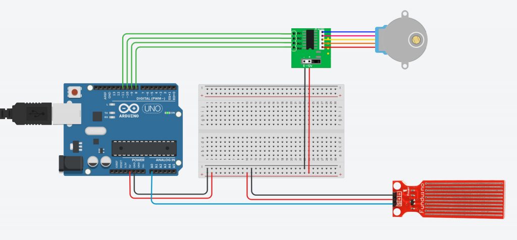
To create this project, first, I checked that the water level sensor was reading the analog data as soon as a submerge it into the water. I simply connected the jumper wires to the 5V, the ground and to the analog read. Then, I connected the stepper motor to H-Bridge and into the Arduino to pins 8-11.
How it works:
The Arduino is constantly reading the input data from the Water Level Sensor. 0 means that the sensor is out of the water; as soon as it gets submerged the data start bumping up to approximately 400. I used this value to tell the stepper motor when to turn on. It is also possible to modify the direction of rotation depending on the range of values from the sensor. There are infinite possibilities! I imagine using this scheme in applications such as in boats, aquatic designs. I quite like the idea of using the water as a trigger. What if the sensor is a trigger to create a musical instrument were the water is the medium?
Problems:
I had some issues with the coding part. The water sensor was giving me values every second when It was by itself. But as soon I connected the motor, it started reading every turn which is not ideal. I couldn’t solve this issue with coding. I had to increase the speed of the motor, so the reading happened quicker.
Arduino Code (File):
https://www.dropbox.com/s/vlz4gihrfu8y3ro/Stepper_Dario.ino?dl=0
Circuit Diagrams:
Resources:
http://engyfun.blogspot.com/2015/02/here-is-source-code-for-our-28byj48.html
https://github.com/joycemolly/stepper-motor-and-h-bridge/blob/master/sketch_mar13a.ino
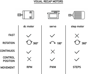
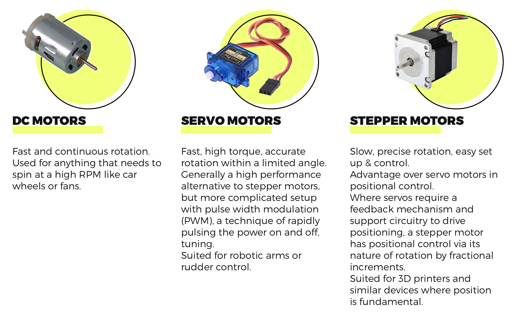
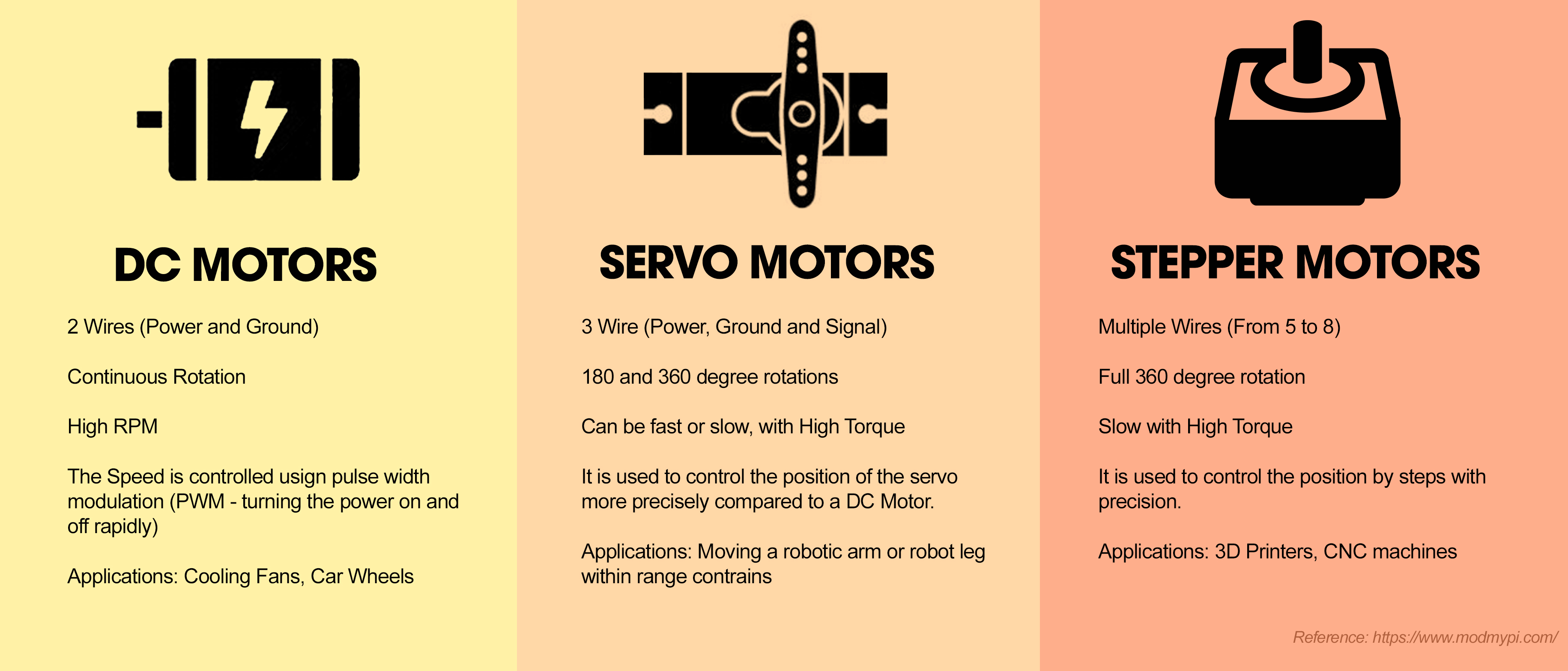
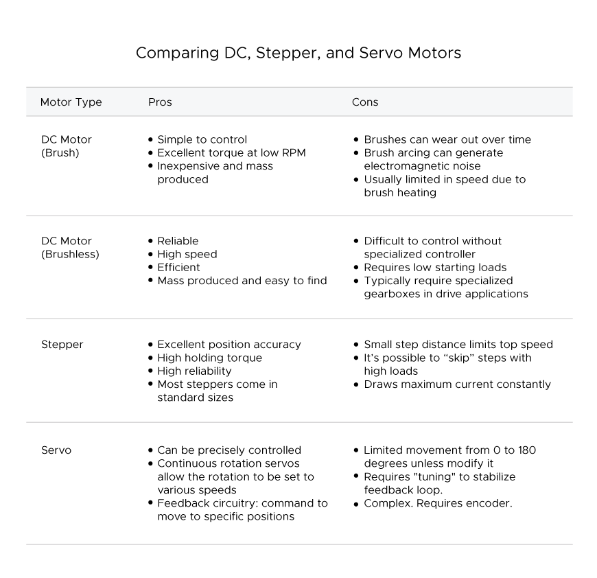
What are the different motors?
DC motors rotate continuously. Their speed is controlled by PWM, which actually turns the motor on and off so rapidly it looks like a smooth movement. DC motors rotate until power is detached.
Servo motors are good for exact tasks because they can be more precisely controlled than standard DC motors. Power to the motor is constant but regulated by the servo control circuit. PWM “unlike DC motors it’s the duration of the positive pulse that determines the position, rather than speed, of the servo shaft.” (source: https://www.quora.com/What-is-the-difference-between-a-DC-motor-a-servomotor-and-a-stepper-motor)
Stepper motors use electromagnets around a central gear to determine the position. Each electromagnet must be individually powered to make the motor shaft turn.

My main goal was to overcome a past frustration using the servo motor. Decision bot 1.0 aim is to help us make those daily complicated decisions such as: “Should I have another coffee?” or “Should I eat a cookie?”. (My roommates asked more interesting questions though).
Goal of the project : create a robotic ouija board
Core components : servo motor, arduino, a button and a resistor
How it works : when the button is pressed the robotic hand moves randomly to a 0-360 degree pointing to one letter at the time
Arduino code:
Continue reading