- Refined project description
My concept is a little bit abstract, so I’m going to show my design question first:
How might a concept without visible instance like dark matter be represented for a better understanding?
My concept in order to answer that is a Experiential apparatus/ installation on perceiving a scientific concept (dark matter) for a better understanding.
This concept is based on a experimental installation trying to explore on different ways to “visualize” the concept including all senses but emphasizing haptics.
A whole system of small micro-experiences could be the result within a context of a bigger exhibition space such a science museum space installation.
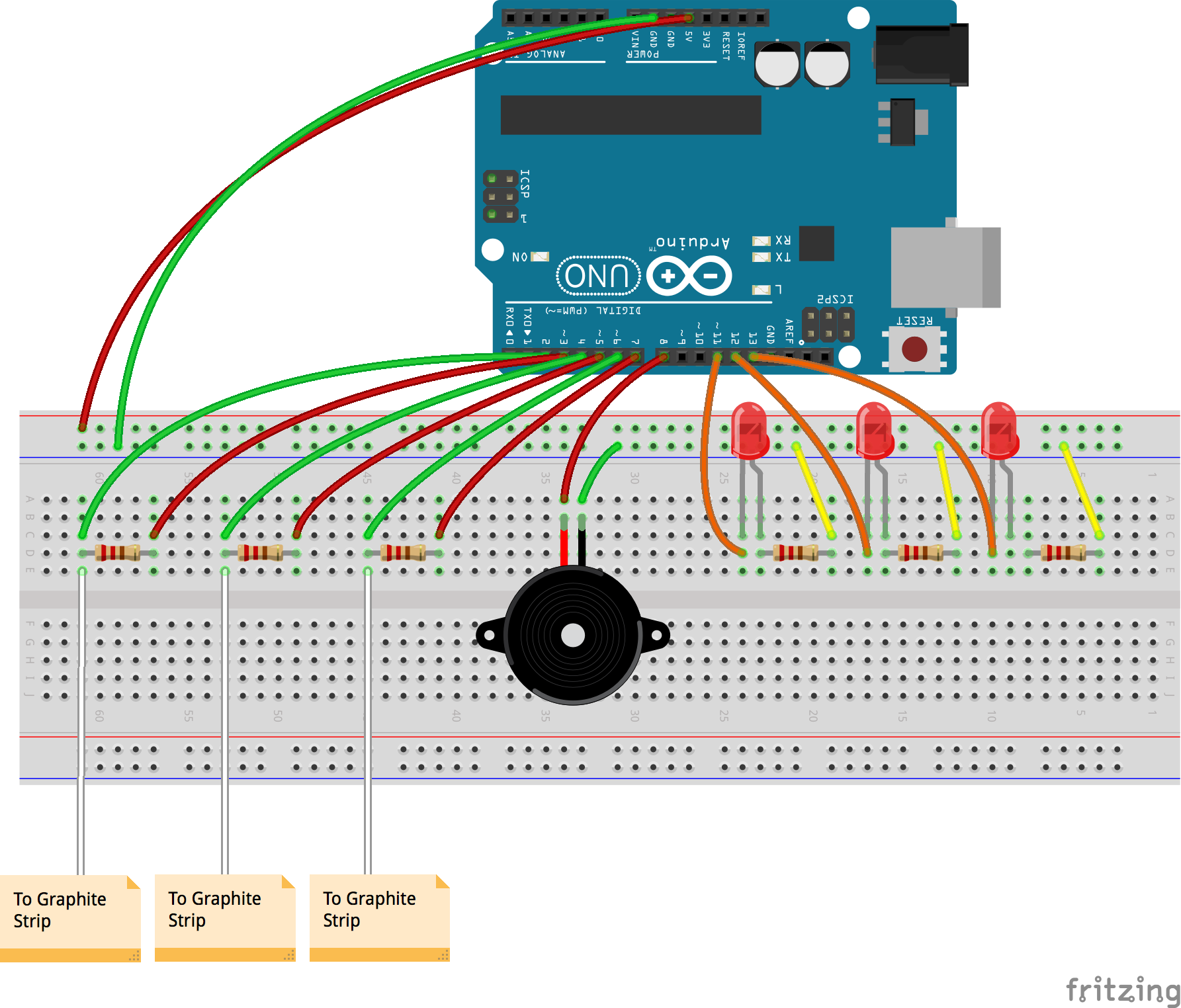
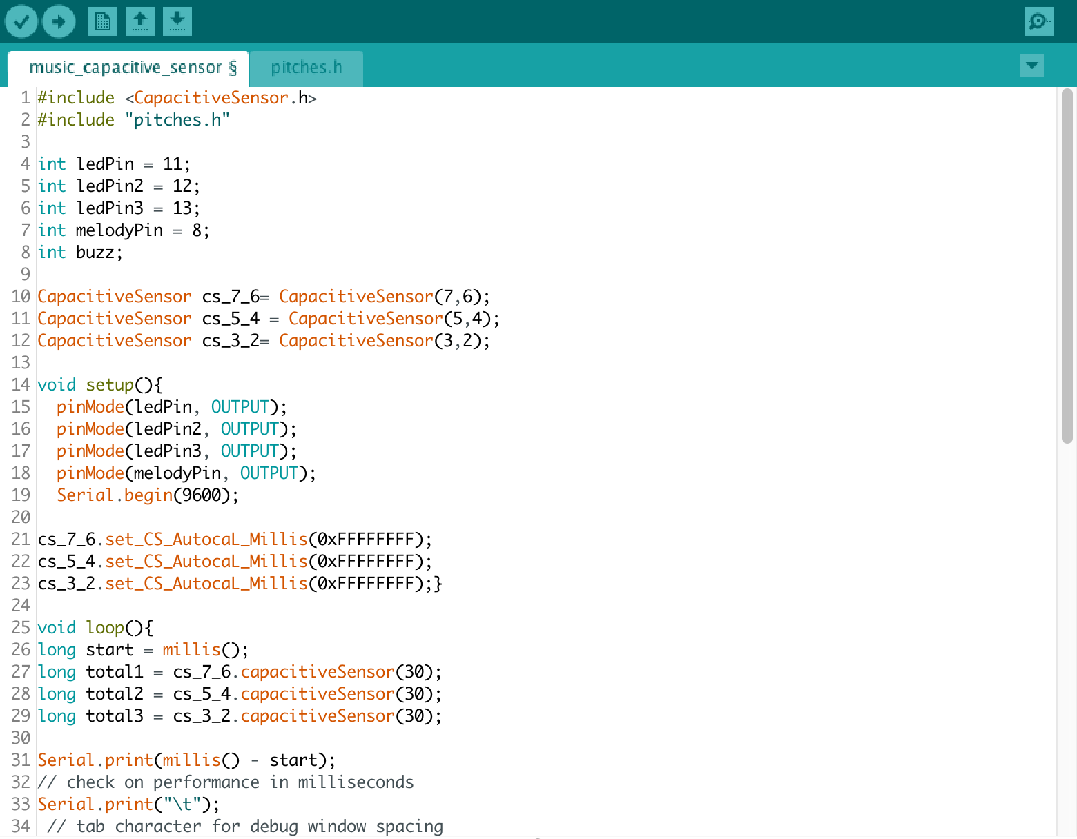
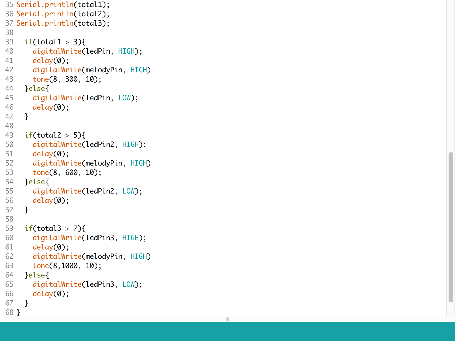
- Interaction/systems diagram
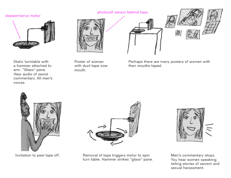
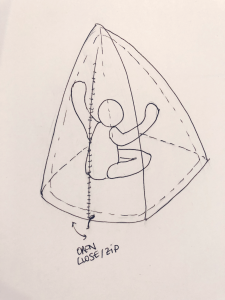
I’m still trying to define the form of my project, right now what I have in mind is this. I need to run several test to see if it’s feasible and it works as expected.
At this point, I see the installation in the shape of a haptic teepee. The user gets in to experience dark matter by touching and triggering the system with those interactions.
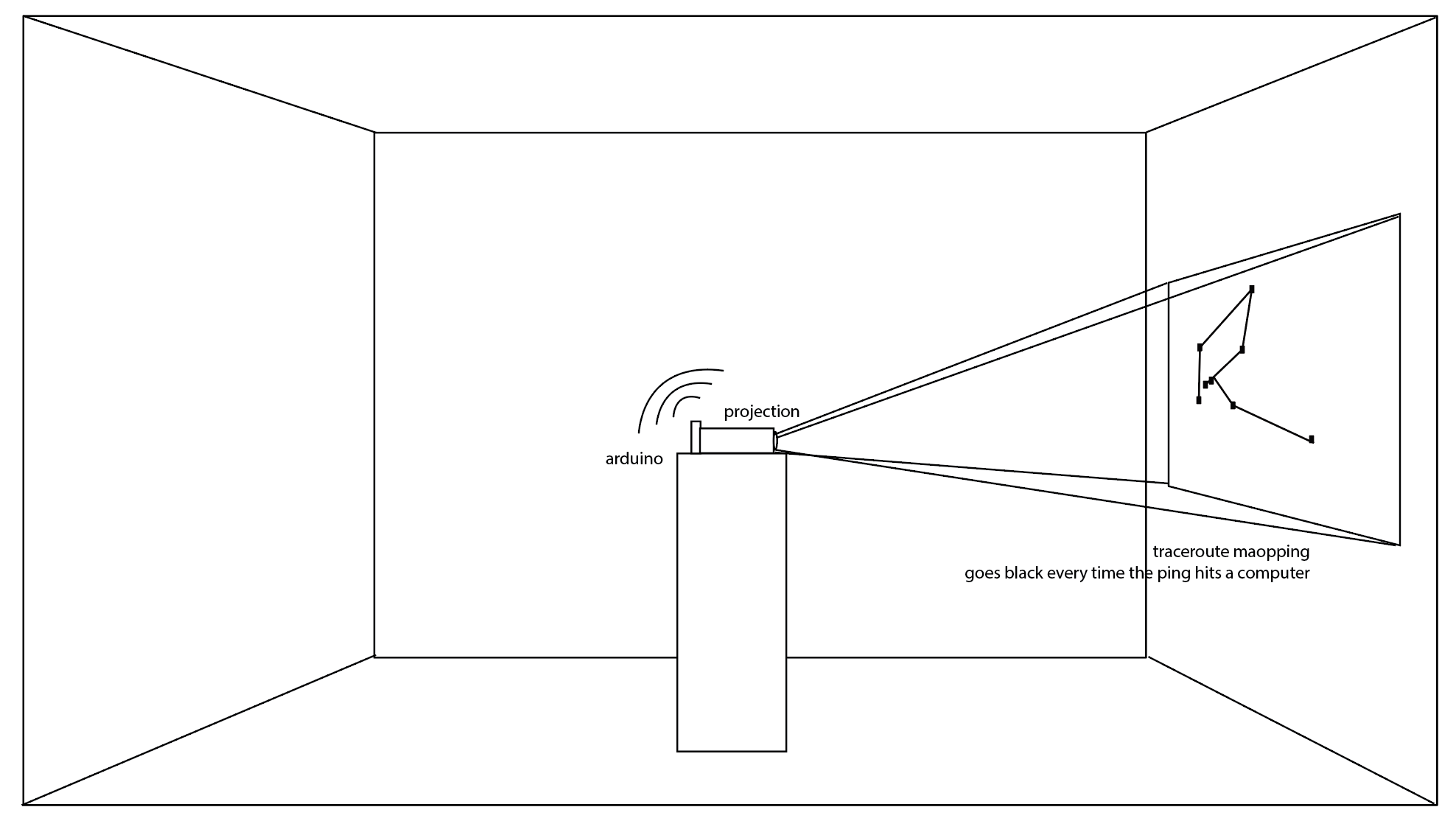
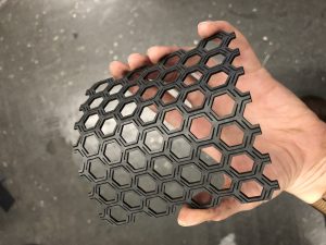
This is a more defined sketch. The inner pyramid, the cubicle, it’s covered by latex ( 2 sides + entrance. The outer structure has 2 sides of lights made of a mesh of LED’s. In between, there is a layer of chipboard connected to a stepper motor that will change its shape depending on the tension applied to the material by pulling a string and bending the board.
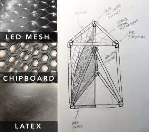
This tension will change the shape and as a consequence the shadow projected to the latex might seem closer or farther.
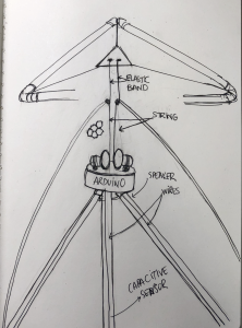
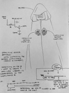
This is a more detailed drawing of the tech schematics.
- Timeline with milestones

- Materials list
Pcomp
- Arduino
- Power supply
- Wire
- 2 steppers
- Capacitive sensors
- 1 x Speaker
- Led Mesh
- Strings and rubber bands
- Capacitive shield
- conductive material
- Solder
Other
- Chipboard
- PVC tubes and connectors
- Latex
- Precedents or references
- Referents
TACTILE DOME
https://www.exploratorium.edu/visit/west-gallery/tactile-dome
JENNY SABINE WORK
http://www.jennysabin.com/new-page/
ANILA QUAYYUM AGHA