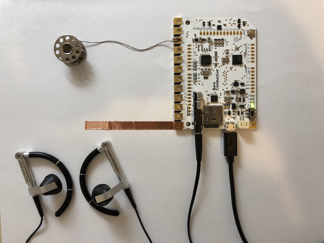
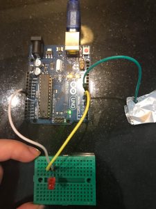
General : I tested Bare conductive’s touch board. I put different 12 drum sounds into micro SD card chip inside the board, so that each 12 nodes of the board make assigned drum sounds. I plugged in headphone to the board, and I could hear loud and clear sound from the board.
Finger with direct touch : Firstly I tried to touch directly with my finger to each node.
Conductive materials : I tried two conductive materials – copper tape and conductive thread. They were all successful.
Distant sense (proximity) : I tested if the touch board is reacting even if it is not actually touched. It was working, but the distance has to be closer than I expected. I adjusted the value of the proximity in the code, and the maximum distance value was about 5 cm.
Volume of the sound : It was adjustable in the code.
I am interested in how the future of connectedness not only in regards to technology but the interpersonal connections that we are currently experiencing in the digital realm, with the likes of social media, can be furthered in a physical space.
I propose a speculative wearable that allows for an interpersonal connectedness to our environment. I was fascinated after reading an article about how trees use mycorrhizal fungi to communicate through underground networks. This communication allows a network of trees to send warning signals about environmental change, search for kin, and transfer nutrients to neighboring plants before they die. This is similar to how neural networks in the human brain work.
This line a questioning has led to interpreting how a possible future of society would derive if humans could communicate through similar networks, a network of nonverbal intuitive intercommunication. The uses for this could have further applications should as physical and psychological therapies.
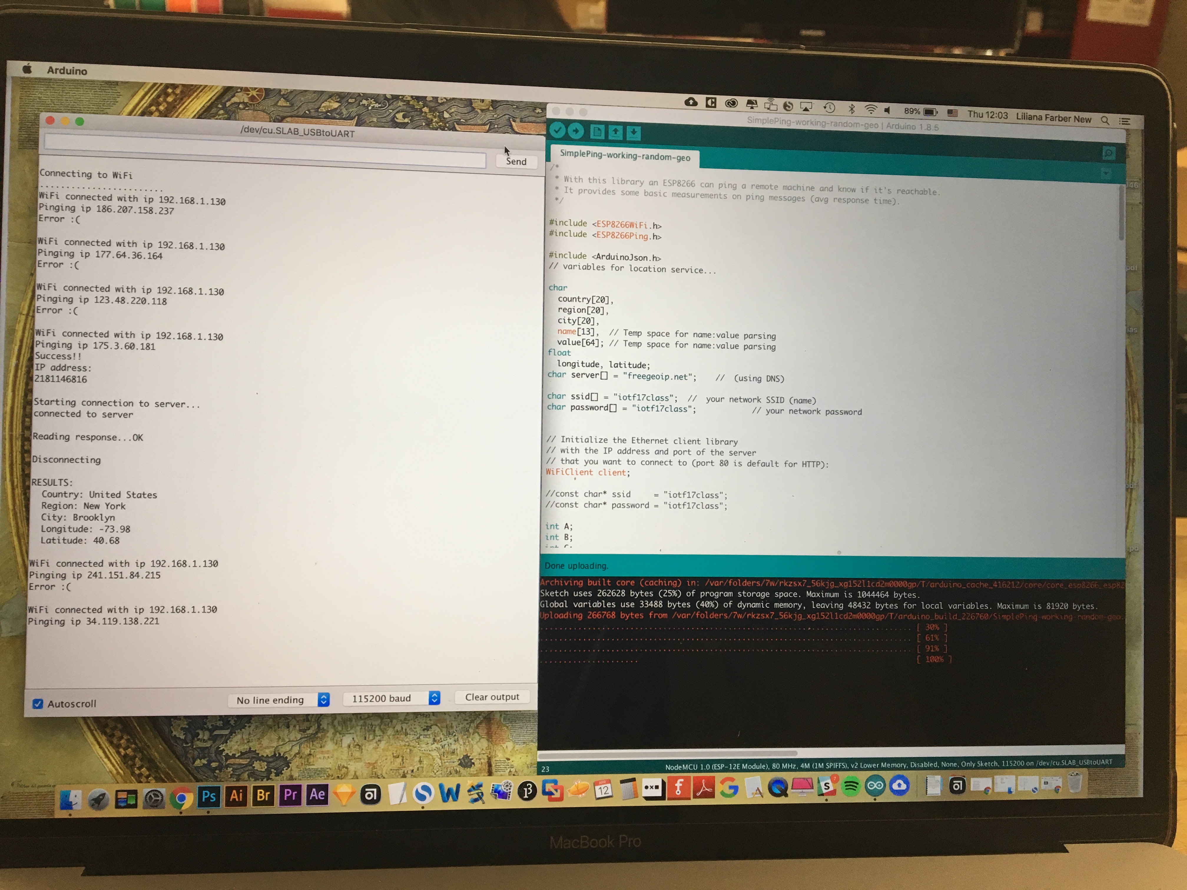
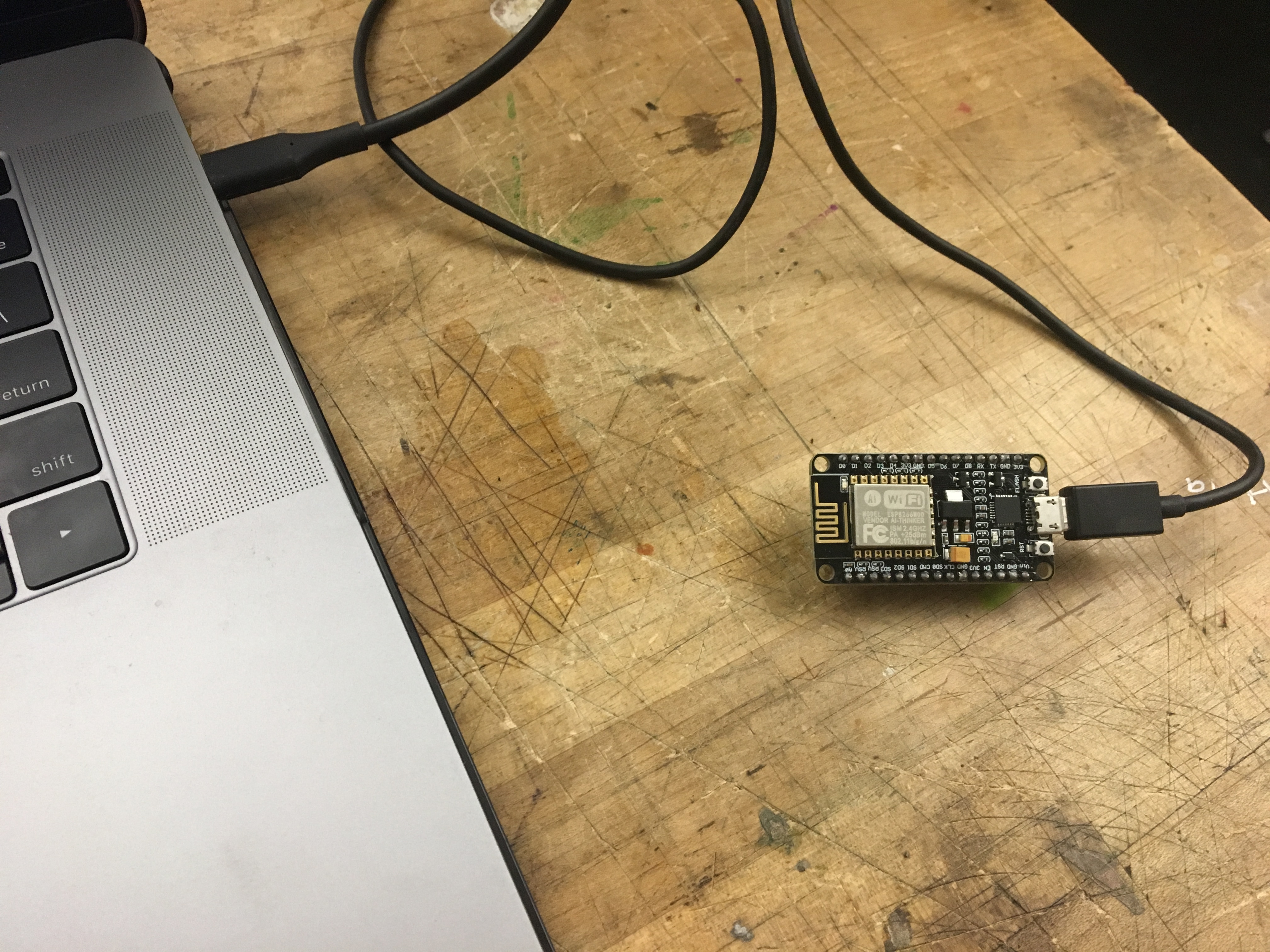
I started to work with a ESP8266 NodeMCU module to connect to Internet and perform continuous ping commands to random IP numbers. After a few trials and errors I was successful. I then moved to include a repository for finding the IP geolocation. I then hit a wall with the library for this module. It seems that the Adafruit version of the ESP8266 has better documentation for creating the geolocation so I ordered one.
My idea originally was to create a laser projector that points to the IP coordinates. After an intensive search I’m not sure this would be possible using a ESP8266 module. I’m still asking around to see if there’s a way of doing it but also thinking of alternative ways to display the information.
I’m using the following repositories:
At this time, there are mainly two ideas that I am thinking about. This past semester, I have been intrigued by the interaction between man and machine- the areas of overlap, the process of co-creation, almost-collaboration that has become commonplace as traditional processes become automated. This area of inquiry is very nuanced and layered- which makes it difficult to categorize it into the binaries of good/ bad or right/ wrong. I am imagining an exhibit, with two different sections- one about machines and humans creating generative art together. The second would be about machines re-inforcing human bias.
The second idea revolves around poetry and power. I want to infuse optimism in instances which show the very worst of human existence- by changing the context of the narrative. I envision a space, with a series of artifacts that explore this theme.
Timeline
Week 11: April 2nd – April 8th
Research, brainstorm, ideate and keep refining the concept statement. Define the audience and context of use. Look at relevant precedents and work that inspires me. Experiment with different ways of inputting information.
Week 12: April 9th – April 15th
Finalize project form. Prototype the technical build of the project and simultaneously start thinking about the look and feel.
Week 13: April 16th – April 22nd
Start assembling/ working on the smaller circuitry that will be a part of the larger project. At the same time, start building/ working on the final fabrication.
Week 14: April 23rd – April 29th
Keep working on the final project. Start preparing the presentation (research + precedents + concept + project documentation).
Week 15: April 30th – May 6
Work on the final presentation. Refine the project by maybe having supplemental material?
The Form
The form is still nebulous and I am undecided about what would be the most effective expression of my concept.
Prototype 1
My idea is still in the conceptualization stages. For the first prototype, I was experimenting with some tools and sensors that I have always been curious about but have never got an opportunity to integrate into my work.
Trial 1
I am intrigued by the idea of being able to draw with the Arduino- especially using different/ unusual input methods. I am also curious about whether the same “sketch” can be modified by two different individuals, interacting with separate systems. To begin with, I tried connecting the Arduino to p5.js, a javascript library that is useful for creating graphics and interactive experiences. The breadboard setup was simple- a 10K potentiometer, with one leg to the 5V power supply, the second to Analog input pin A1, and the third to the ground of the breadboard. I mapped the analog readings of the potentiometer from a range of 0 to 1023 to 0 to 255 and then printed the values on the serial monitor.
The web server cannot communicate with the serial port directly. There is an application called p5.serialcontrol that helps serve this function. One can control the ports using the app. There is also a Javascript file with relevant event and callback functions that need to be included in the p5 file to get it to work.
What I did get working: I was able to connect the Arduino to p5.js, using a locally run web server
What is not working: The readings are very erroneous, and unstable- they keep fluctuating
Next steps: Potentially connect two different laptops and work on the same visual output using multiple sensors ( potentiometer + light sensor)
Trial 2
Using the temperature and humidity sensor: Again, the wiring is very basic but I am having troubles with installing and using the library. Will keep working on this. I don’t know whether this is the right sensor for trying to detect someone blowing air/ changes in the immediate environment because of hand gestures/ body movement.
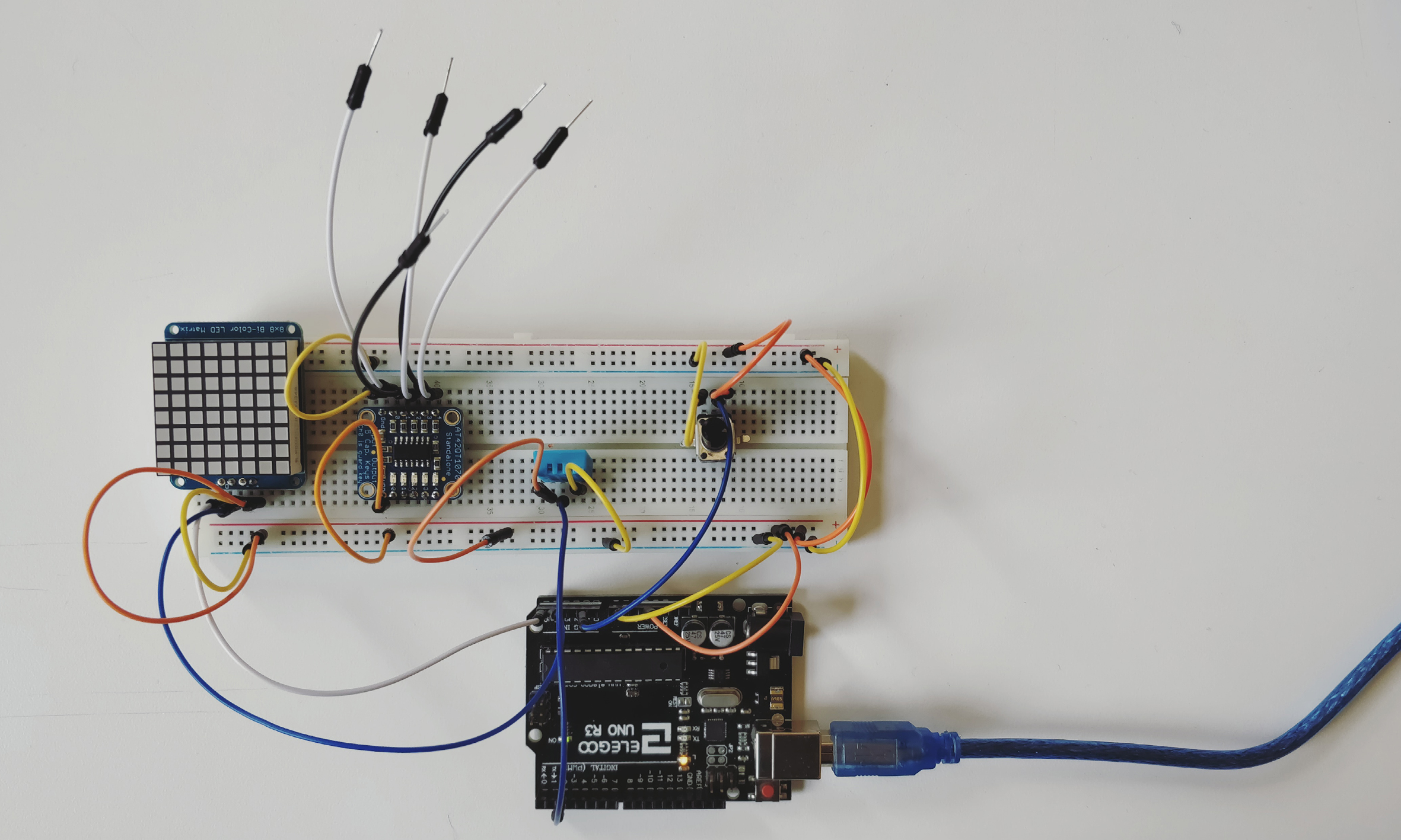
Trial 3
Using the standalone 5- pad capacitive touch sensor breakout. This particular component is really interesting. It does not need to be operated via a micro-controller and functions well by itself. The wiring is really simple- the details of which are available on https://www.adafruit.com/product/1362. After having worked on capacitive sensing a few weeks back, I was surprised at the sensitivity and level of precision this board provided.
Next steps: I want to connect the board to other outputs- like motors/ LED’s to see how it will work
Trial 4
Another component that I have had for a long time but never had a chance to use is the 8*8 Bicolor LED matrix. The wiring is standard and is included on the site. The matrix can be programmed to show different graphical outputs.
Next steps and questions: Could a programme translate a drawing that the user makes into coordinates that could be displayed on a matrix? Can multiple matrices display different portions of the same “sketch”?
While taking the video, I realized that taking a close up of the LEDs gives very interesting visual results.
Create a post with
1) The next iteration of your prototype.
Use the class documentation format. 2) Your playtesting plan and desired feedback.
To think about: Who will you playtest with? How will you get their consent? What feedback do you want? What questions will you ask? What information do they need to know before starting? How much will you help them during the test? How will you debrief them?
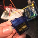
This week I prototyped the most basic functionality of my project:
when the photocell is covered, servo motor stops. When photocell is uncovered, servo motor sweeps 180º.
Over the next week I will iterate on this by both multiplying instances of the functionality and giving shape to the story (adding the hammer to the motor, embedding photocell in foam core poster).
I used a few web resources for this code, which are listed at the top of my .ino sketch for now.
DC motors: Is the simplest of the motors. There are two terminals. When you apply direct current to one terminal and ground the to the other, the motor starts spinning.
DC motors are usually very fast, often spinning at several thousand revolutions per minute (RPM).
Will keep spinning until power is taken away
Depending on electricity the faster or slower it goes.
Gearhead motors: subset of DC motors that replaces speed for power.
Examples include computer cooling fans and toy wheels
Widely used in robotics because of their small size and high energy output.
Servo motors:Servo motors are small in size but very energy efficient and precise.
Consist of four components:
DC motor
A gearing set
A control circuit
A position-sensor (usually a potentiometer)
A servo motor can usually only turn 90° in either direction for a total of 180° movement.
Servo motor are controlled by sending electrical pulse width modulation (PWM).
Stepper motors:
The motor’s position can then be commanded to move and hold at one of these steps without any position sensor for feedback (an open-loop controller), as long as the motor is carefully sized to the application in respect to torque and speed.
Precise positional control, move 1 step each time
Slower than DC
Don’t need to get feedback during the rotation
To change direction change polarity.
How do they work: they work on the principle of electromagnetic induction. When you put an electric current through a wire- it generates magnetic field around the wire.
The blue and red portions are the magnet shields.
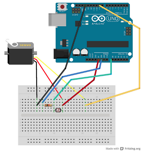
Objective: The goal of this project is to better understand how a servo motor can be controlled with a potentiometer through an Arduino. Goal of the project and/or desired interaction
Materials:
-Arduino + USB Cable
-3x M-F jumper cables
-3x M-M jumper cables
-Potentiometer
-Servo Motor
-Breadboard
Assembly:
Servo Motor:
-Connect power wire (red) to the 5V pin on the Arduino
-Connect ground wire (brown) ground pin on the bread board.
-Connect signal pin (orange) to pin 9 on the Arduino.
Potentiometer:
-Plug into breadboard with room for placing cables.
-Outer pins are connected to power (+5V) and ground via directly next to the (+5V) and ground on the bread board.
-Middle pin is connected to analog input 0 on the Arduino.
Download:
-Library Servo.h
-Code Servo Motor Code
Download the library, upload the code, and now you have control over the servo motor.
Thanks to this great Instructables I now better understand the motor components.
This prototype is making for my Major Studio final project, I will give a simple intro and a draft to show what I will make in this semester.
design statement:
In order to improve the creativity and imagination of 4th to 8th grades (early adolescence) in the 10-14 years age group, I designed an interactive installation that invites collaborative artwork in a community. Thought the use of a digital pen and Wacom pad, and a sensor that can detect the color of everyday objects, students can simultaneous paint on a large digital screen.
My initial idea of this installation is you can input any color you like, from any objects (use RGB sensor). Then you can create a brush by mix the different geometric figures (use camera sensor). From now I can get the color from the RGB sensor but it’s not that stable, also I met a problem when I use openFrameworks to read the three value (RGB) through Arduino.
Materials list:
RGB sensor
button
UNO
breadboard
Precedents:
1:
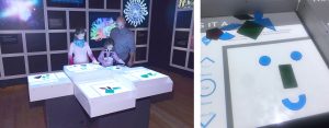
I got a reference from the Our Senses exhibition, as the image show, a user can play with the puzzles and the digital screen will give them an feedback on the result of machine learning. People will enjoy the process of making puzzles plus interacting with the screen. From what I have seen in this installation, people will be more passionate and engage when they can see something reacts to their input.
2:
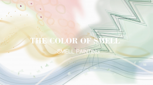
“The Color of Smell” is an interactive tool project which enables to paint with the smell, it consists of a selection of smells, synthetic and natural, a smell-brush and a mutitouch table top. This project can draw different shapes based on the smell you input from the objects, and this function really inspires me that how to surprise the user. So I want to classify a color input from the user, then different color ranges have a specific brush.
So far this has been a successful second attempt at making a working capacitive sensor. As seen through the second video featuring the serial monitor and the code once the capacity passes a certain threshold (1000) the LED will turn on. Alone the capacity of the aluminum foil and the environment have stayed under the threshold, nevertheless the capacity has been changing frequently from 60s-90s to 250s-290s.
Next Step:
My goals for this week are to meet with a few people who are more capable of coding to show me how to set Boolean and if-statements according to the sensed capacity. I’ve also ordered the Arduino thermal printer last week, now I am waiting for its arrival.
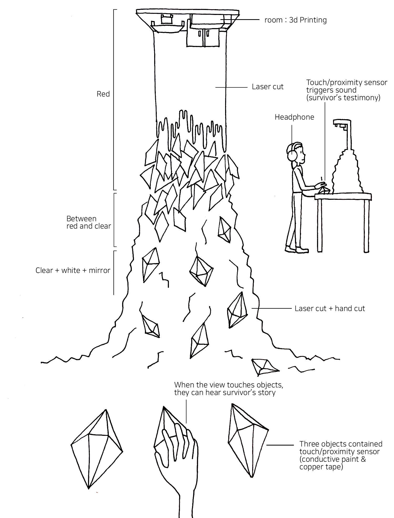
I am planning to make a sound installation that reveals the cruel reality of domestic abuse against women and children. This installation will be produced in order to encourage hidden survivors of DA (Domestic Abuse) to speak out publicly or privately so that they might receive appropriate support, and enlighten general citizens the reality and prevalence of sexual abuse in family and further, influence policy-makers to provide adequate measurements.
I know personally a woman who is a survivor of DA, and I am going to record her testimony directly. Based on this woman’s real voice and true story, the installation will illustrate the space where all these horrors happened, her room. In order to give satirical and reversing notion against traditional idea of family, I will create a miniature room – as a visually scary place using vivid red color material and weirdly distorted form by laser cut and 3D printing. The structure and objects of this miniature room will follow the real room of hers based on her testimony. The room will be upside down at the top of the installation, and lots of fragments and 3d shapes will be hanging from the room miniature like a waterfall. The fragments shapes are red when it is close to the room, but as it goes down, they will turn clear/white/mirror color. This symbolizes survivor’s eventual freedom and her current status to influence other people. 3 shapes are separately put on in front of the table and they contain touch/proximity sensor. Viewers are provided a headphone, and when they touch each objects, they can hear survivor’s story turn to turn.