Goal of the Project:
The intention with this project was to explore the capabilities of sensors connected to an Arduino, and how with the transformed data it is possible to create statements (conditionals) to achieve different purposes. In this particular case, the proposal was to create conditionals by mapping the values of a distance sensor and a photoresistor in order to light up or turn off and Led.
Conditions:
- If the environment is bright, the LED won’t light up.
- If the environment is dark but the distance is far away, the LED won’t light up.
- If the environment is dark and the distance is close, the LED will light up.
List of Components:
- x1 Arduino Uno
- x1 Breadboard
- x1 Distance Sensor
- x1 Photoresistor
- x1 RED LED
- x1 220 kohm Resistors (for the LED)
- x1 10 kohm Resistors (for the photosensor)
- Jumper Wires
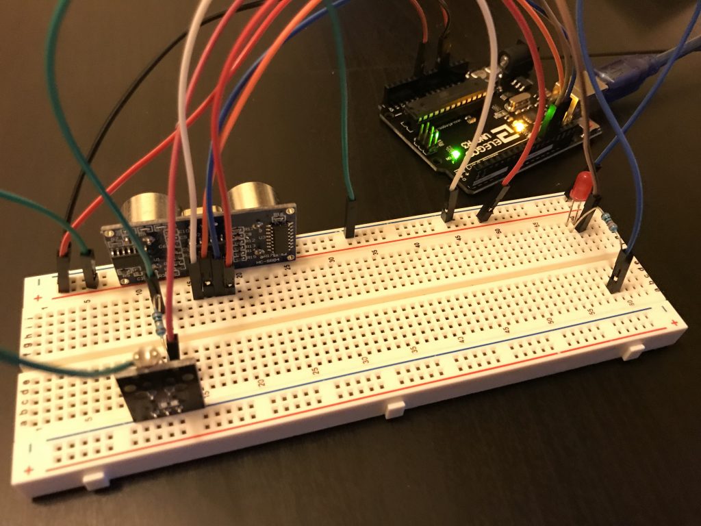
Assembly Process:
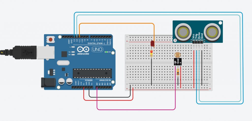
A good practice to create this circuit consists to connect each sensor (one by one) and check if the microcontroller is reading the data and is doing it correctly. First, the LED is connected, positive side to pin 11, and negative to a 10kohm resistor and ground. The Distance Sensor Trig and Echo are connected to pins 13 and 12 respectably. The photoresistor is connected to the Analog Pin A0.
How it works:
The Arduino program is constantly reading 3 conditions: If it’s bright (more than 30 for the photoresistor sensorValue), then the LED is off (LOW). if (sensorValue > 30), then: digitalWrite(led,LOW). If it’s dark and the distance to the sensor is more than 10cms, then the LED is off (LOW). if (distance > 10 && sensorValue < 30), then digitalWrite(led,LOW). Finally, if it’s dark and the distance to the sensor is less than 10cms, then turn on the led (HIGH). if (distance < 10 && sensorValue < 30), then, digitalWrite(led,HIGH).
Problems:
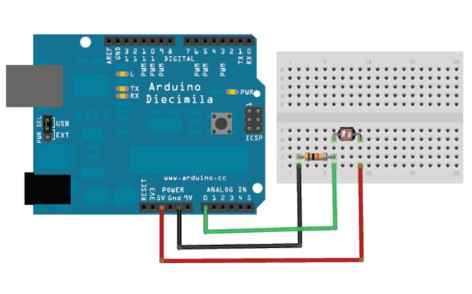
The main issue doing this exercise was trying to understand the Photoresistor I had available. The one that I have it’s from Elegoo and it has 3 connections instead of 2. In this case, it’s a bit more convenience when I want to connect the different wires to the breadboard and to the Arduino. I just had to check the “info-sheet” of the product.

Arduino Code (File):
https://www.dropbox.com/s/wb1e1fnj43sxcen/DarioNarvaez_HW_5.ino?dl=0
Circuit Diagrams:
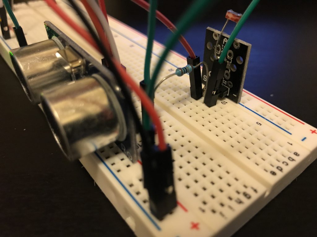
Alternative Photo-Resistor Connection: