Concept
At this time, there are mainly two ideas that I am thinking about. This past semester, I have been intrigued by the interaction between man and machine- the areas of overlap, the process of co-creation, almost-collaboration that has become commonplace as traditional processes become automated. This area of inquiry is very nuanced and layered- which makes it difficult to categorize it into the binaries of good/ bad or right/ wrong. I am imagining an exhibit, with two different sections- one about machines and humans creating generative art together. The second would be about machines re-inforcing human bias.
The second idea revolves around poetry and power. I want to infuse optimism in instances which show the very worst of human existence- by changing the context of the narrative. I envision a space, with a series of artifacts that explore this theme.
Timeline
Week 11: April 2nd – April 8th
Research, brainstorm, ideate and keep refining the concept statement. Define the audience and context of use. Look at relevant precedents and work that inspires me. Experiment with different ways of inputting information.
Week 12: April 9th – April 15th
Finalize project form. Prototype the technical build of the project and simultaneously start thinking about the look and feel.
Week 13: April 16th – April 22nd
Start assembling/ working on the smaller circuitry that will be a part of the larger project. At the same time, start building/ working on the final fabrication.
Week 14: April 23rd – April 29th
Keep working on the final project. Start preparing the presentation (research + precedents + concept + project documentation).
Week 15: April 30th – May 6
Work on the final presentation. Refine the project by maybe having supplemental material?
The Form
The form is still nebulous and I am undecided about what would be the most effective expression of my concept.
Prototype 1
My idea is still in the conceptualization stages. For the first prototype, I was experimenting with some tools and sensors that I have always been curious about but have never got an opportunity to integrate into my work.
Trial 1
I am intrigued by the idea of being able to draw with the Arduino- especially using different/ unusual input methods. I am also curious about whether the same “sketch” can be modified by two different individuals, interacting with separate systems. To begin with, I tried connecting the Arduino to p5.js, a javascript library that is useful for creating graphics and interactive experiences. The breadboard setup was simple- a 10K potentiometer, with one leg to the 5V power supply, the second to Analog input pin A1, and the third to the ground of the breadboard. I mapped the analog readings of the potentiometer from a range of 0 to 1023 to 0 to 255 and then printed the values on the serial monitor.
The web server cannot communicate with the serial port directly. There is an application called p5.serialcontrol that helps serve this function. One can control the ports using the app. There is also a Javascript file with relevant event and callback functions that need to be included in the p5 file to get it to work.
What I did get working: I was able to connect the Arduino to p5.js, using a locally run web server
What is not working: The readings are very erroneous, and unstable- they keep fluctuating
Next steps: Potentially connect two different laptops and work on the same visual output using multiple sensors ( potentiometer + light sensor)
Trial 2
Using the temperature and humidity sensor: Again, the wiring is very basic but I am having troubles with installing and using the library. Will keep working on this. I don’t know whether this is the right sensor for trying to detect someone blowing air/ changes in the immediate environment because of hand gestures/ body movement.
Trial 3
Using the standalone 5- pad capacitive touch sensor breakout. This particular component is really interesting. It does not need to be operated via a micro-controller and functions well by itself. The wiring is really simple- the details of which are available on https://www.adafruit.com/product/1362. After having worked on capacitive sensing a few weeks back, I was surprised at the sensitivity and level of precision this board provided.
Next steps: I want to connect the board to other outputs- like motors/ LED’s to see how it will work
Trial 4
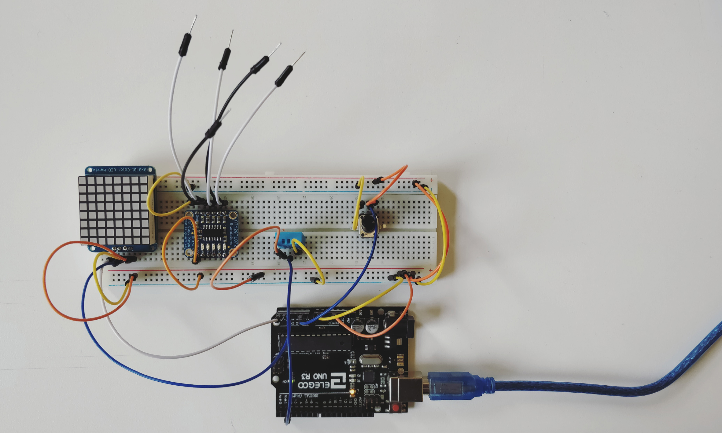
Another component that I have had for a long time but never had a chance to use is the 8*8 Bicolor LED matrix. The wiring is standard and is included on the site. The matrix can be programmed to show different graphical outputs.
Next steps and questions: Could a programme translate a drawing that the user makes into coordinates that could be displayed on a matrix? Can multiple matrices display different portions of the same “sketch”?
While taking the video, I realized that taking a close up of the LEDs gives very interesting visual results.