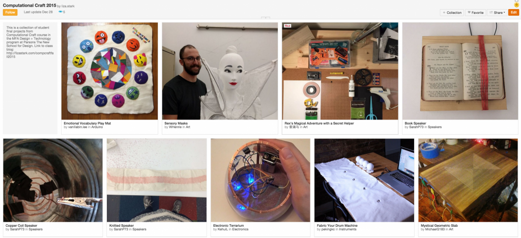
Thanks for a wonderful class this semester! Here is the collection of all of your final projects on Instructables.
Thanks for a wonderful class this semester! Here is the collection of all of your final projects on Instructables.
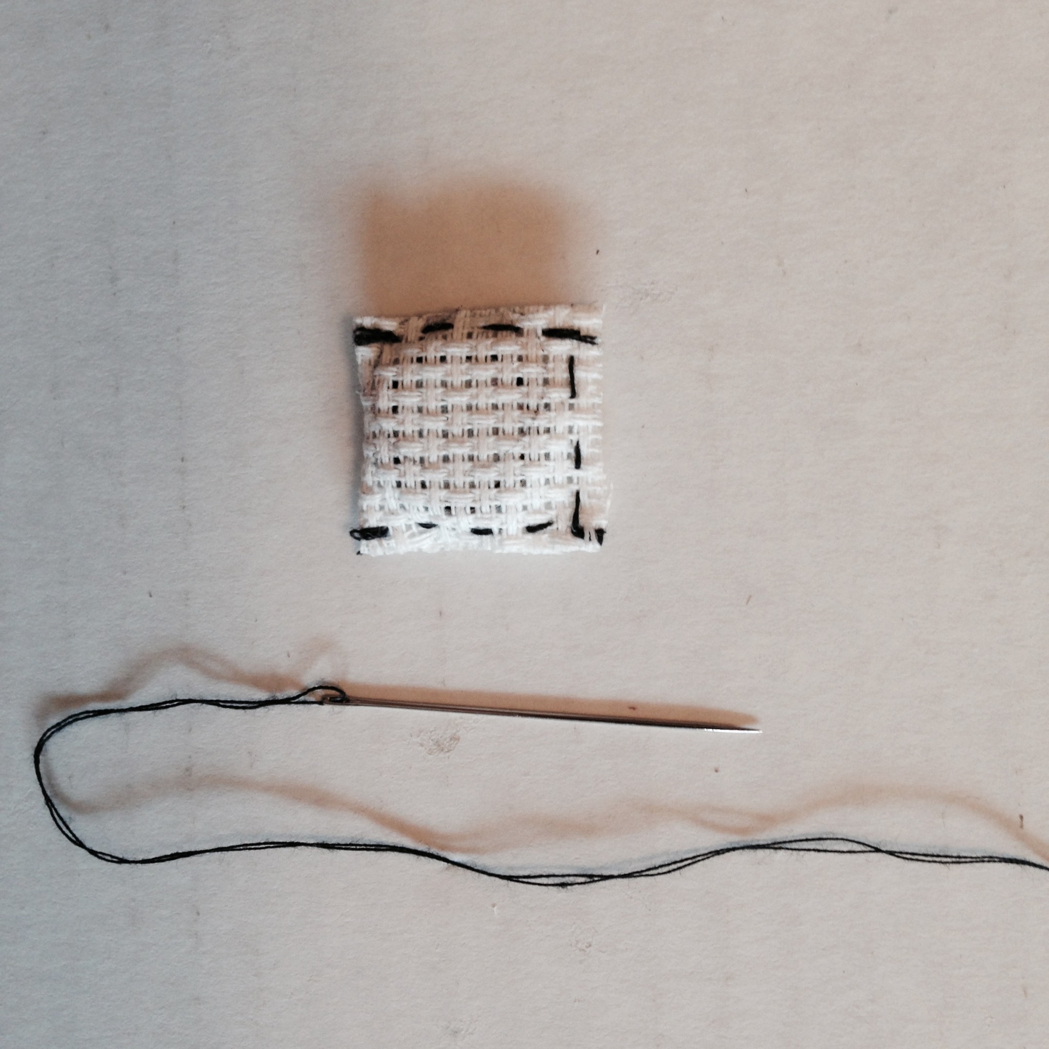
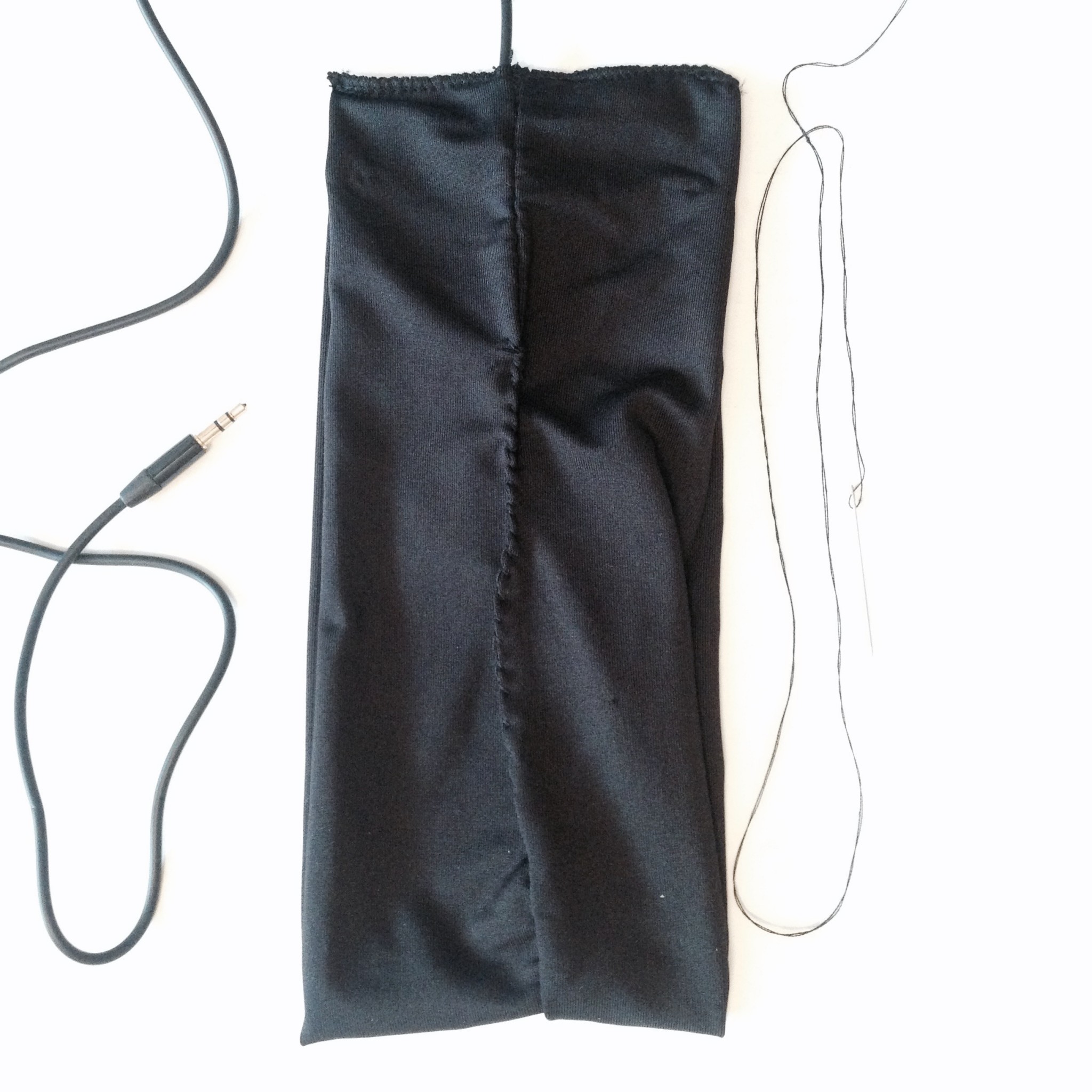
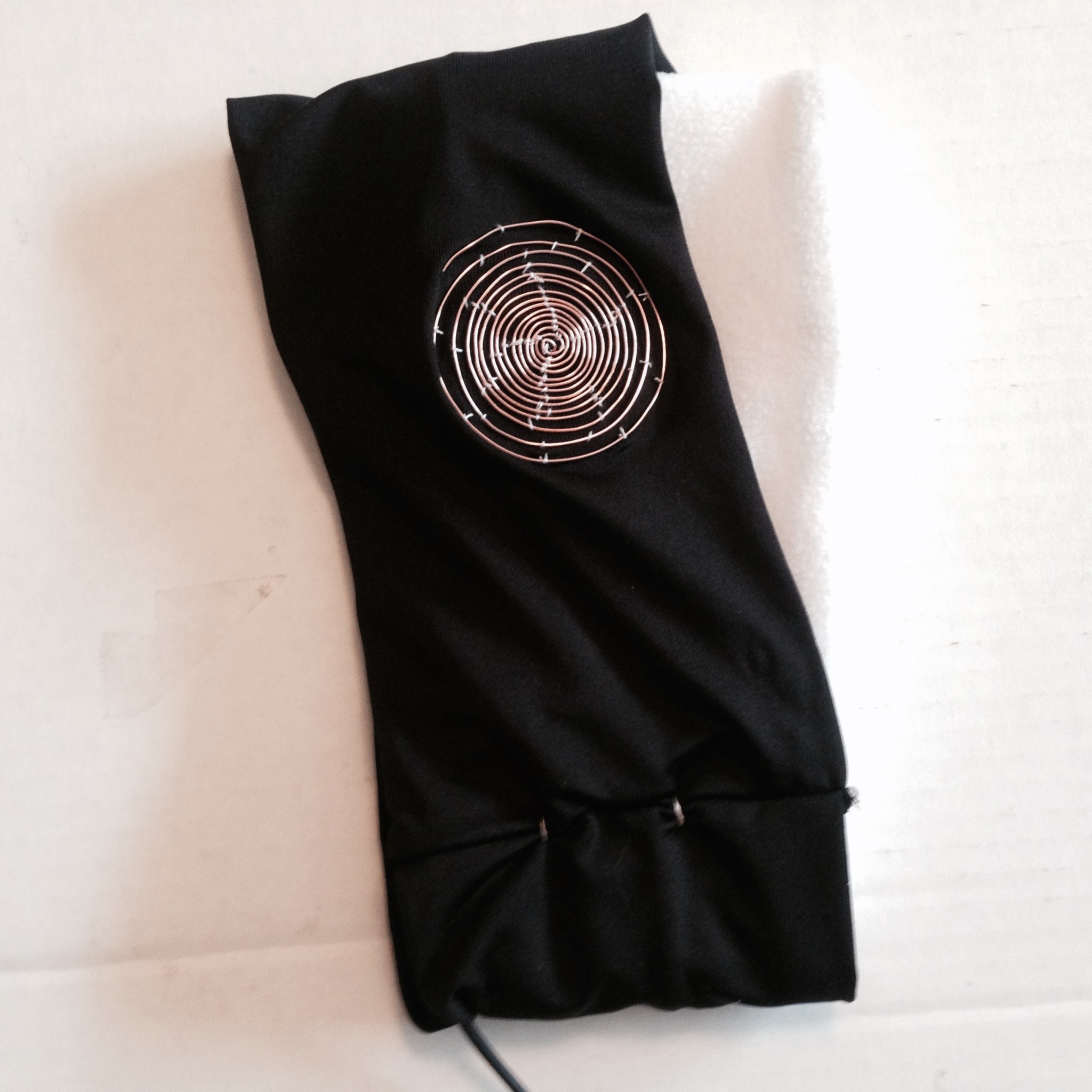
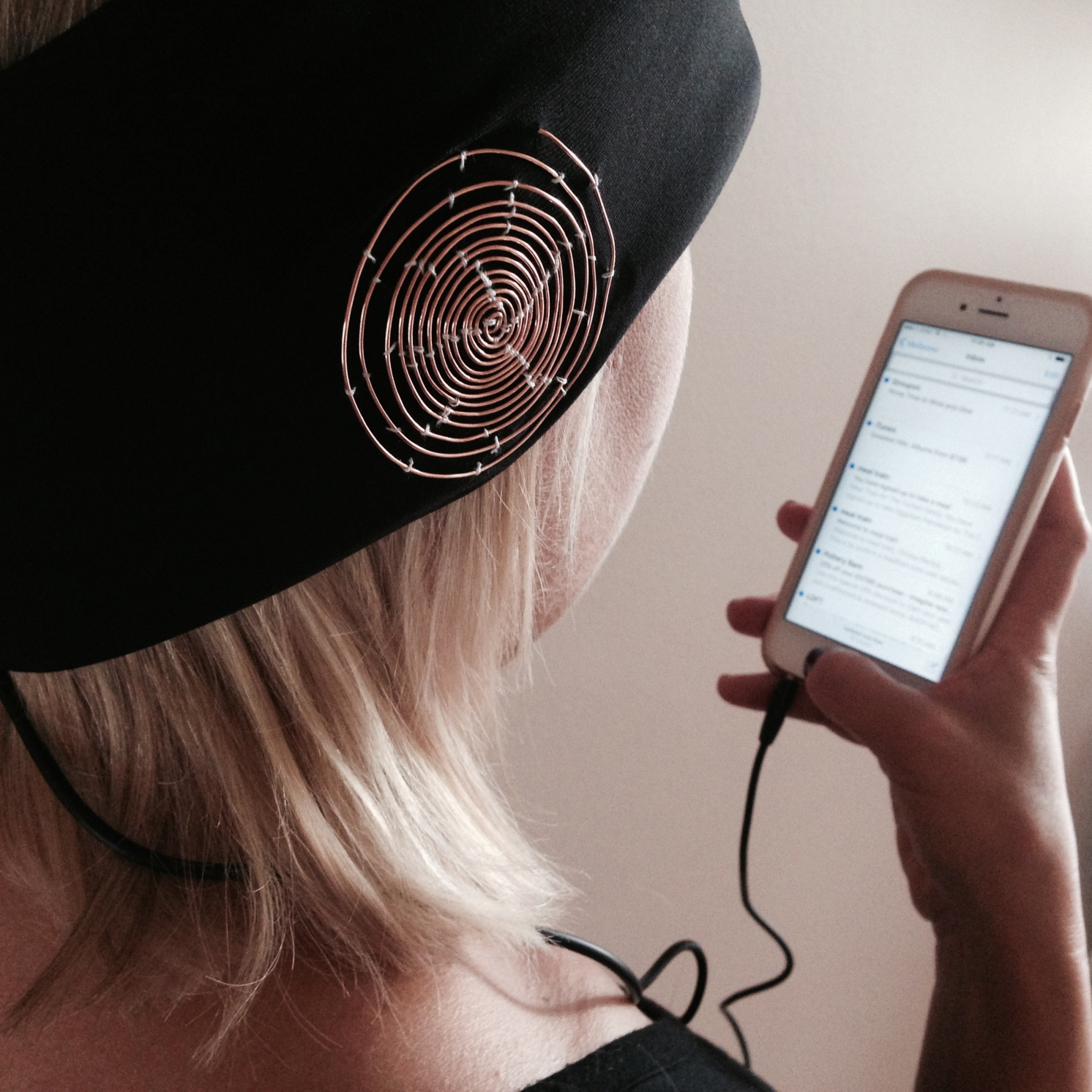
I was very inspired after our final presentation, and decided to re-make my headphones based on the wonderful critique I received. The new design uses the fabric of the headband as the foundation of the speaker to create a more integrated design. I also made the coil a visual focal point by exposing it on the exterior of the headband.
Here are the links to my original post & updated Instructables
Final Process Documentation:


Soft Circuit Loteria Final Project Process and Instructables!
By Isabella Cruz-Chong and Sarah Page
For our main final project post, see this page.
Knitted Speaker in “El Alacran”
Process
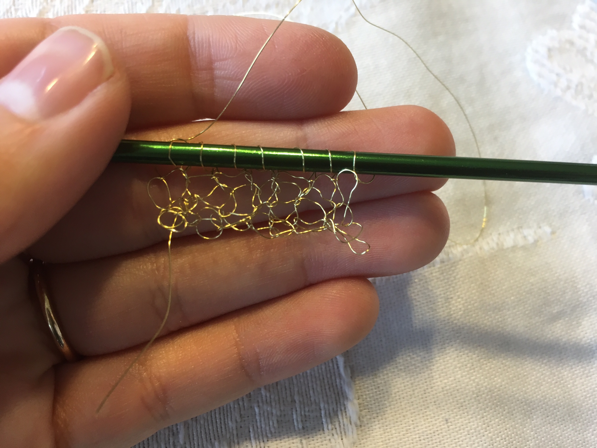
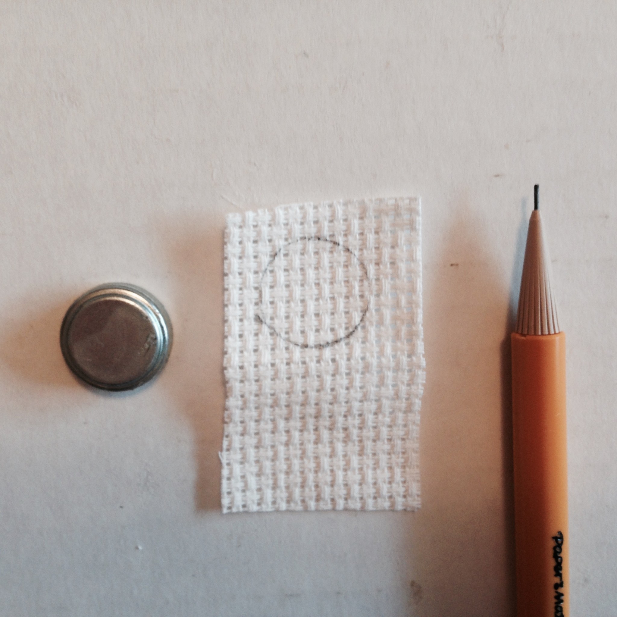
Testing different types of coated wires for the speakers
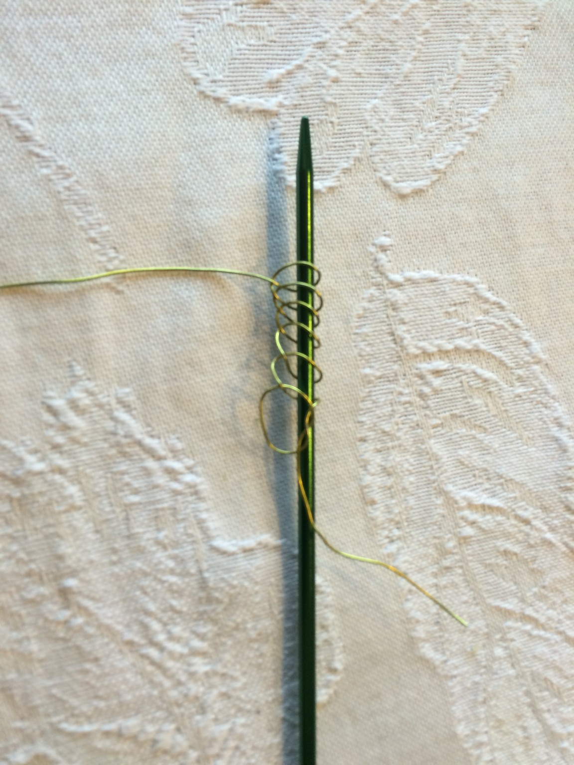
Knitting test with heavier copper wire
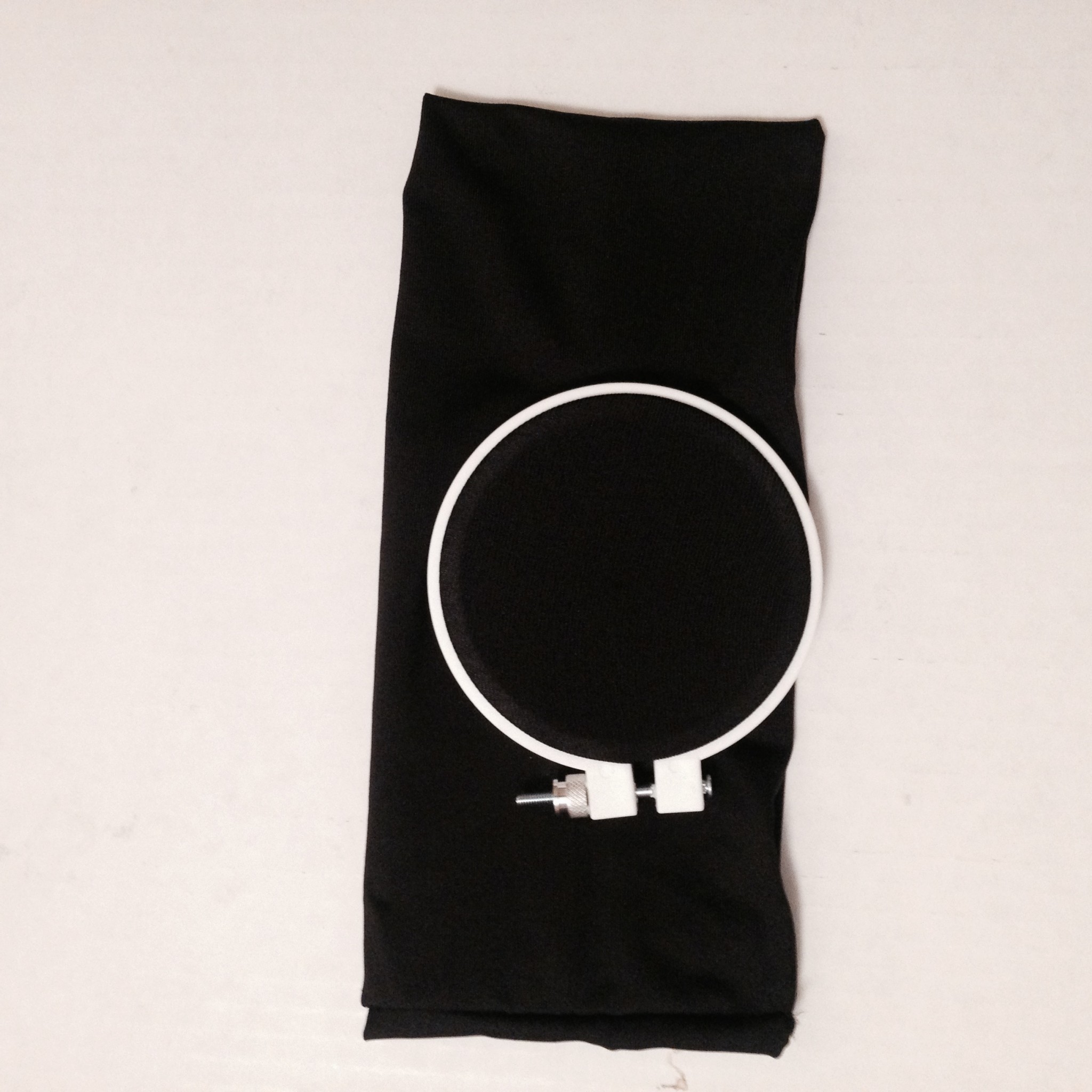
Coiled Speaker in “La Pera”
Process

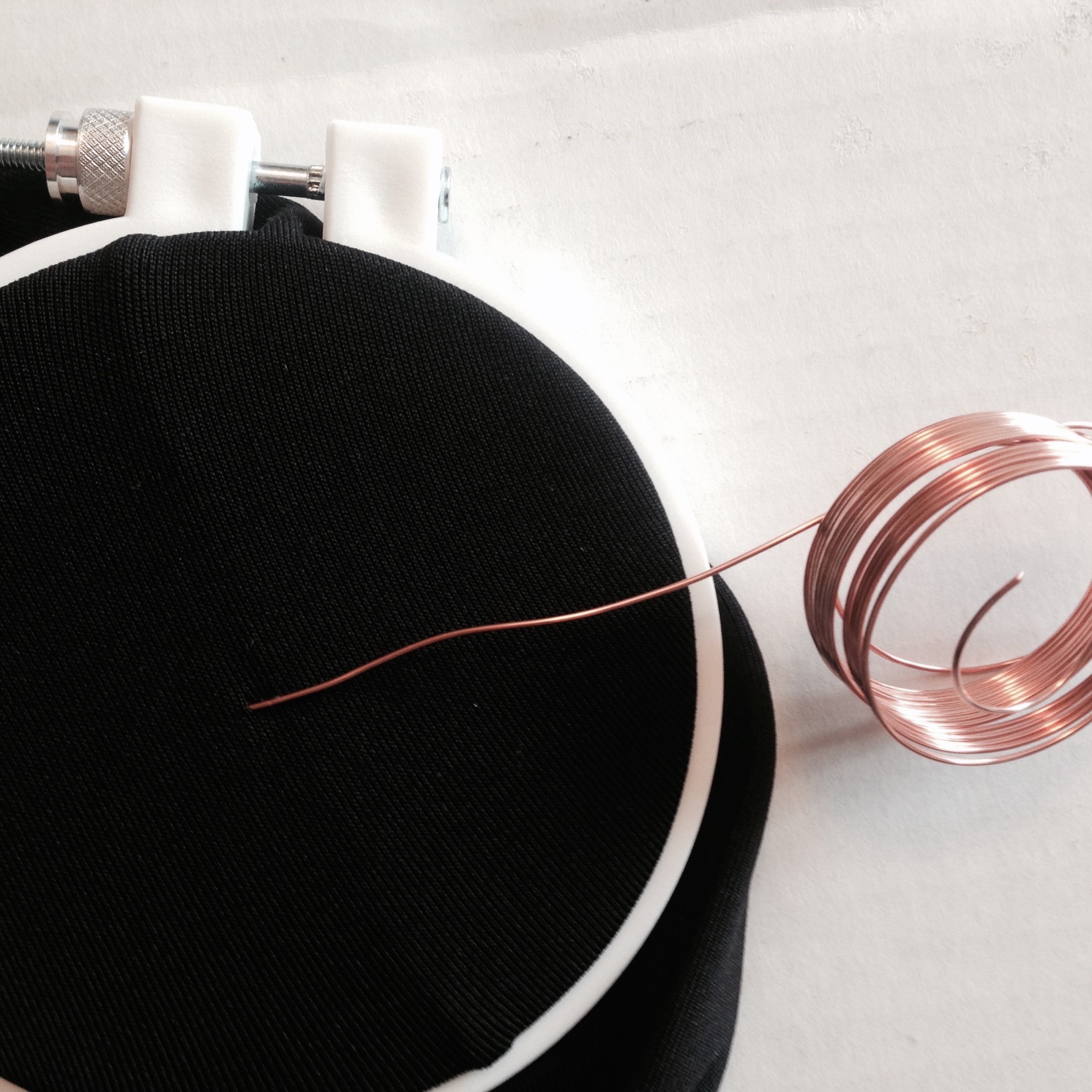
Starting the copper coil
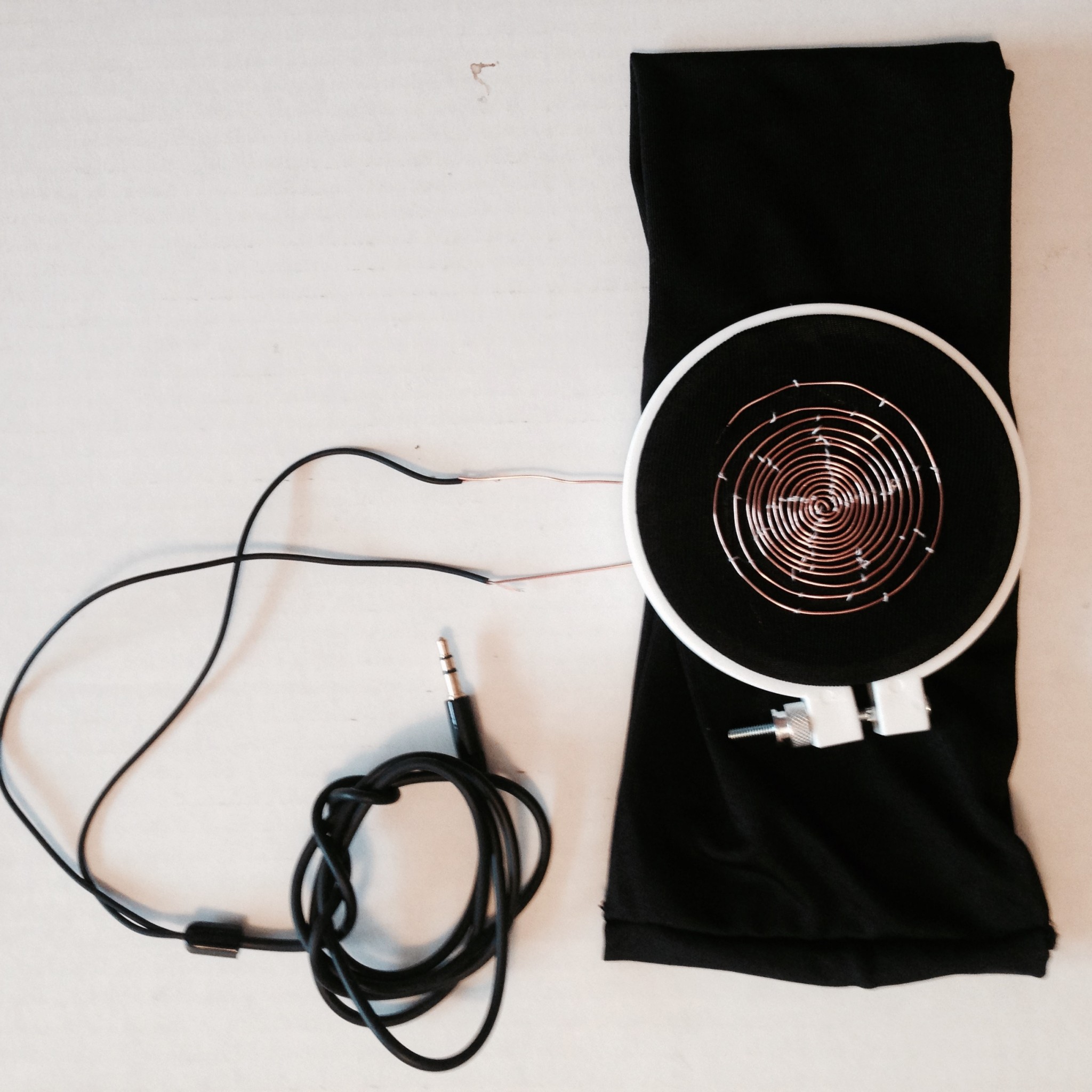
Copper coil speaker test
Copper Coil Speaker Instructable
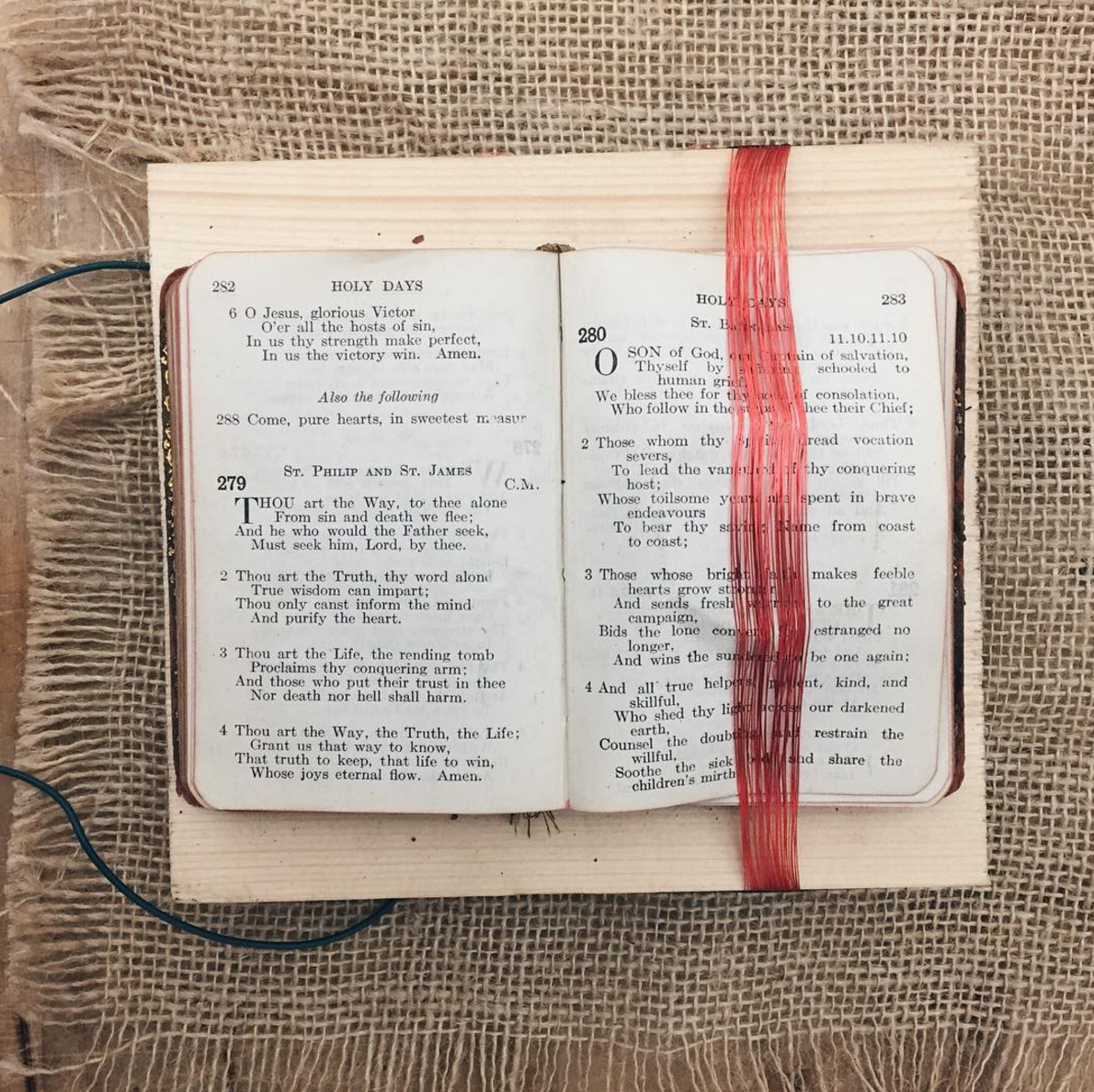
Book Speaker in “El Músico”
Process

Wrapping Wire around book
Book Speaker Test
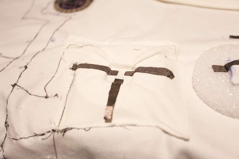
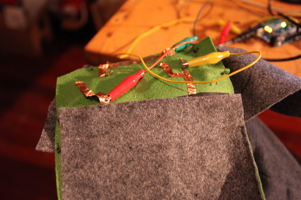
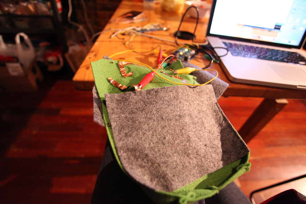
Capacitive Touch Sensor in “El Nopal”
Process
I was inspired by the double pendulum’s random patterns to create something that would capture its patterns randomly for my finals:
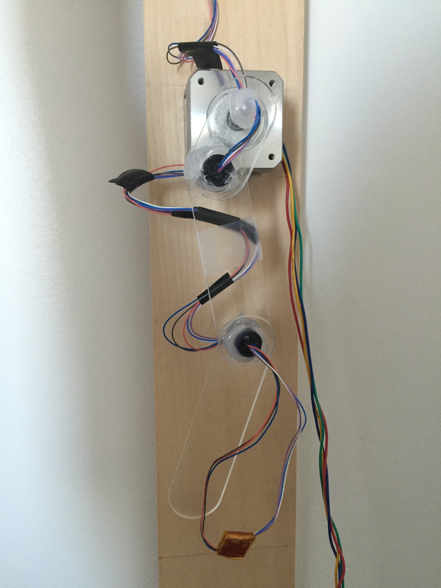
The concept was theoretically simple: I would use a stepper motor and the Easy Stepper Driver from Sparkfun to drive the pendulum, and I would draw the patterns on thermochromic ink with a heating element attached to the pendulum to trace its motion temporarily. All of this would be controlled using a Arduino Pro Mini, though at the beginning, I used an Arduino Uno to prototype.
I powered the motor and driver from Sparkfun using a 12V/1A power source since at first I couldn’t seem to find any concrete information about what kind of power source to use with the driver. I laser cut the pieces for the pendulum from plexiglass and used a slip ring and glue gun to hold them together. The slip ring worked great to wire the heating element at the tip of the pendulum while still allowing for it to swing. I only wished the wires were thicker because the thin ones were flimsy and kept breaking, however, soldering three of them together to create one worked relatively well.
The circuit I used for the heating element is the one found off of How To Get What You Want:
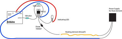
Instead of using the TIP122 transistor though, I used a TIP120 transistor, which according to its spec sheet, can handle up to 60V/5A of power. Throughout working on this project, I used a 9V/1A wall adapter and a 12V/1A wall adapter, and I also briefly tried using a 18V/1.5A battery which I’ll talk more about later. For the heating element, I originally wanted to use flexinol, however it burnt out too easily and its ability to move was a hinder in this case. After some research, I decided to use nichrome wire wrapped between layers of kapton tape for my heating element with much better results.

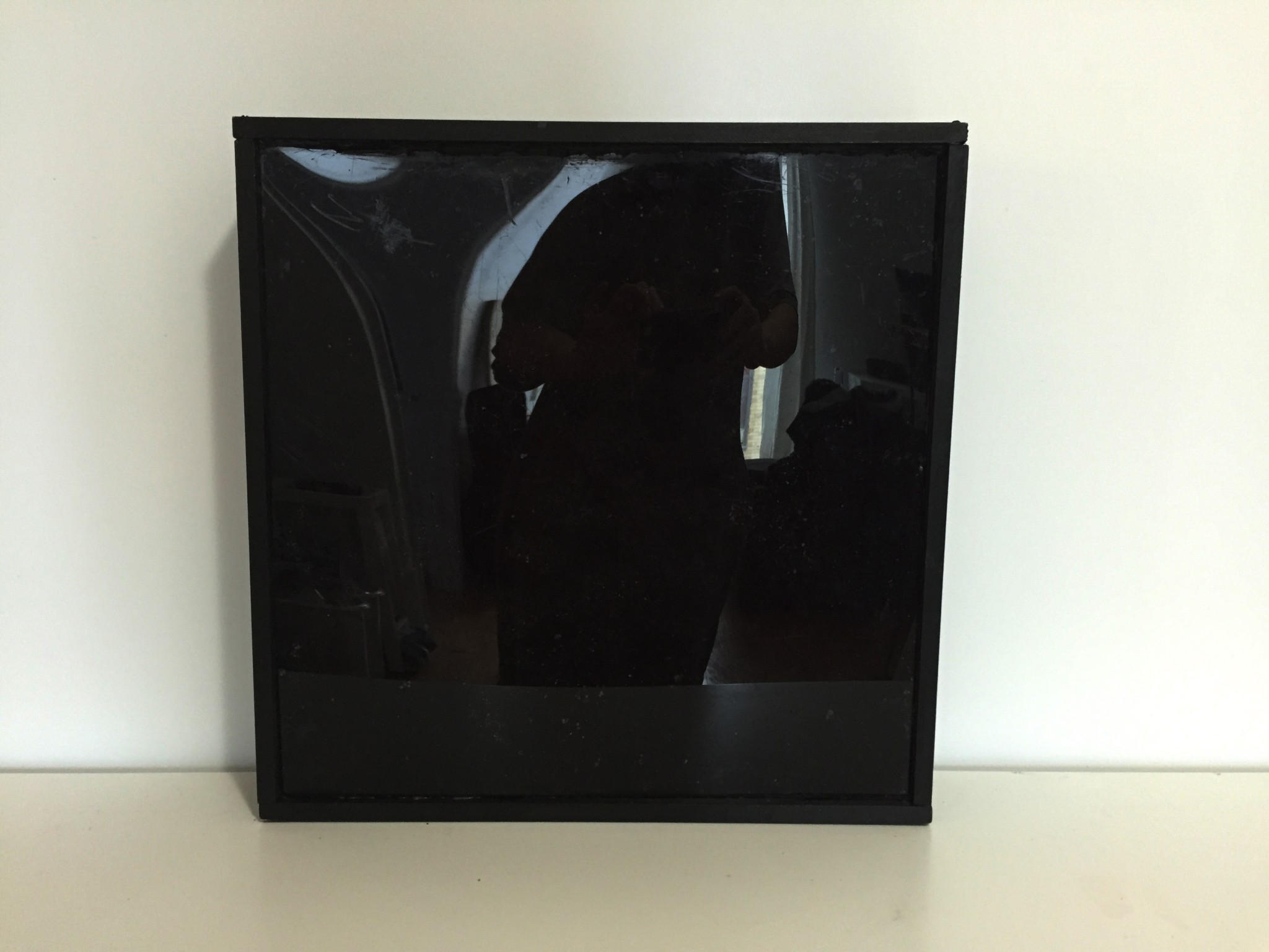
For the “canvas”, I mixed black thermochromic pigment with acrylic fluid matte medium binder, so that when heat was applied to it, the black would fade to an opaque white. Originally, I wanted to spray it onto a large sheet of plexiglass, however, the paint was too thick to go through the spray paint bottle, so I resorted to dabbing paint blobs onto the surface, which resulted in a interesting texture. 
I then built a frame around the plexiglass to which I would attach the motor with the heating element attached to it.
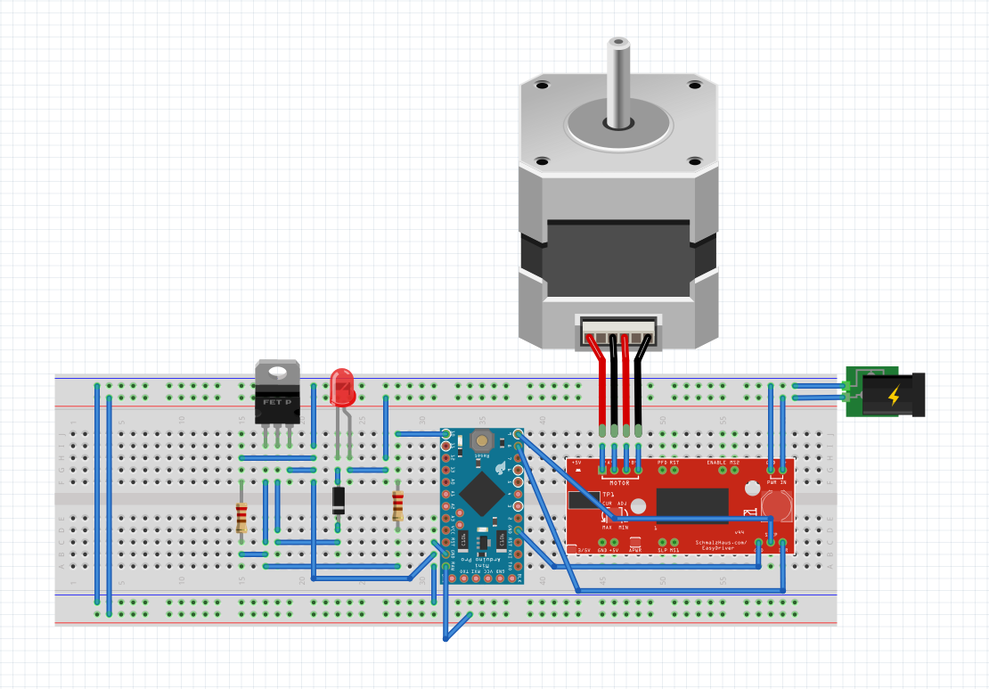
I then soldered the circuits for the motor and heating element together with the Arduino Pro Mini, to run off the same power source (12V/1A). The circuit looked somewhat like this (the heating element is where the red LED is):
The code I was using:
const int DIR = 8;
const int STEP = 9;
const int HEAT = 10;
int distance = 0;
int heatState = LOW;
int stepState = LOW;
unsigned long prevMillisHeat = 0;
unsigned long prevMillisMotor = 0;
unsigned long prevMicrosStep = 0;
unsigned long currentMillis;
unsigned long currentMicros;
long heatInterval = 5000;
long motorInterval = 1;
long stepInterval = 100;
boolean running = true;
void setup() {
pinMode(DIR, OUTPUT);
pinMode(STEP, OUTPUT);
pinMode(HEAT, OUTPUT);
digitalWrite(DIR, LOW);
digitalWrite(STEP, LOW);
}
void loop() {
currentMillis = micros();
heat();
if (currentMillis – prevMillisMotor >= motorInterval) {
prevMillisMotor = currentMillis;
if (running == true) {
motorInterval = 1000;
spin();
Serial.println(distance);
if (distance == 2000) {
if (digitalRead(DIR) == LOW) {
digitalWrite(DIR, HIGH);
} else {
digitalWrite(DIR, LOW);
}
distance = 0;
running = false;
}
} else {
motorInterval = 2000000;
running = true;
Serial.println(“PAUSE ME”);
}
}
}
void spin() {
digitalWrite(STEP, HIGH);
digitalWrite(STEP, LOW);
distance ++;
}
void heat() {
if (currentMillis – prevMillisHeat >= heatInterval) {
prevMillisHeat = currentMillis;
if (heatState == LOW) {
heatInterval = 5000;
heatState = HIGH;
} else {
heatState = LOW;
heatInterval = 100;
}
digitalWrite(HEAT, heatState);
}
}
As a result, my project worked — for a very brief two minutes or so (which was not enough time to grab a camera to document this), before the power source blew. Wondering if it was just a wonky power adapter, I blew two more before I decided that there was something wrong. Exactly what though, I had no idea. Thinking that the 12V/1A adapter was not giving off enough current, I decided to try a 18V/1.5A rechargeable battery which burnt my nichrome wire into smoke and ash as soon as I plugged in the power source. 1.5A with my current circuit was way too much current, and produced way too much heat for the nichrome to handle.
Doing some more investigation, I found that Brian Schmalz (the designer of the driver) wrote:
I have no clue how on earth I missed this! I think because I read the driver can regulate the current to produce 150mA – 700mA, that I thought that 1A would be enough to power the driver. I ended up buying a 12V/2A adapter and prayed it would work.
The problem now, is that 2A would be enough to fry my nichrome, since it’s way more than 1.5A. I had two options: use two power sources, or start thinking a little about physics.
If V = I * R, and E = V * V / R, when I used a 9V/1A power supply, I had roughly 9 watts of power going through the nichrome. For 12V/1A, I had roughly 12W. And 18V/1.5A which caused smoke was roughly 27W. Theoretically if I can keep the W down to ~12W, then I should be able to use 12V/2A. So if I added a 10 ohm resistor to one of the heat lines, that should keep it to roughly 9W of heat going through the nichrome. That’s my theory, but my physics was really, really dusty.
Since I was really short on time, I decided to rewire things to take on two power sources, with this circuit: 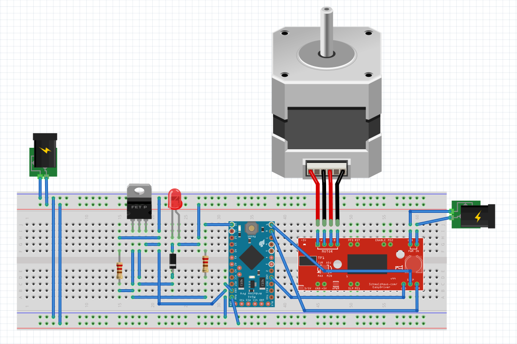
So the motor no longer blew out my adapter, and the nichrome played nice when plugged in separately…. However, when I plugged in both of the power sources at once, the motor wouldn’t spin smoothly, if at all.
At this point, I’m at a loss and not quite sure what’s wrong with my project. So I’m going to accept the fact that some things just weren’t meant to work for the time being and leave it be. I’ll come back to it after some time with a fresh mind and hopefully I’ll figure out what’s wrong.
Instructables: http://www.instructables.com/id/Trace-a-Work-In-Progress
[On Paris]: Honestly, I thought the feedback was alright, but not very useful. It would’ve been great had it come a lot sooner, maybe if we were going back and forth since the beginning of the semester.
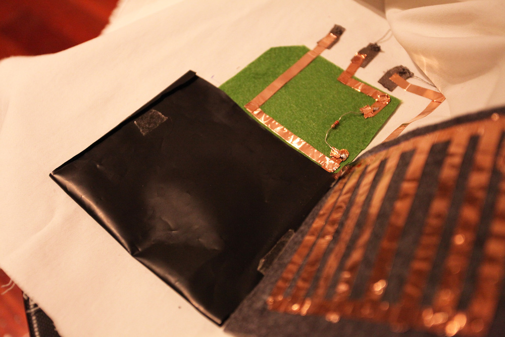
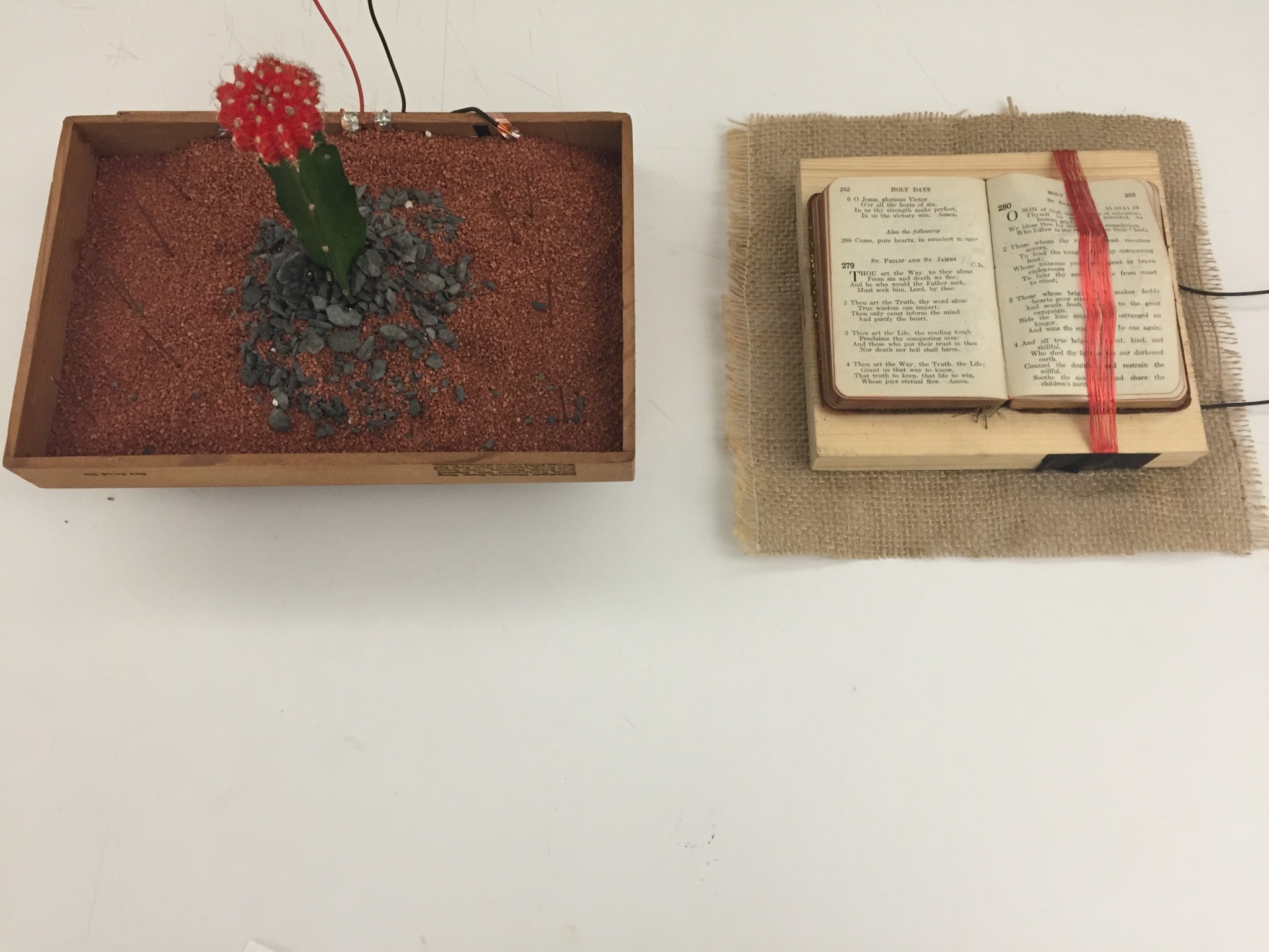
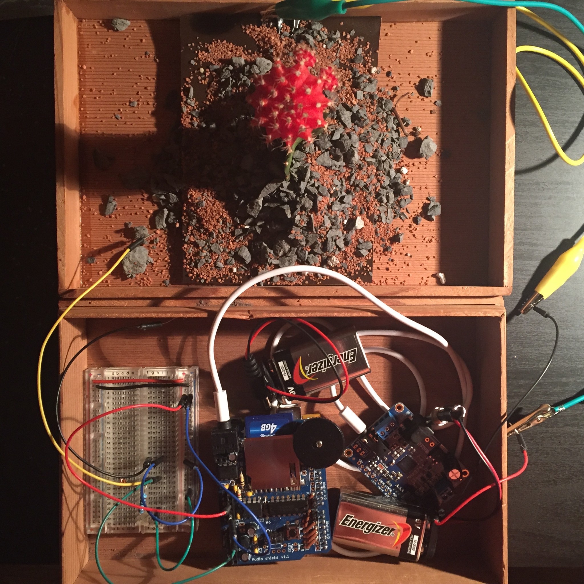
Concept
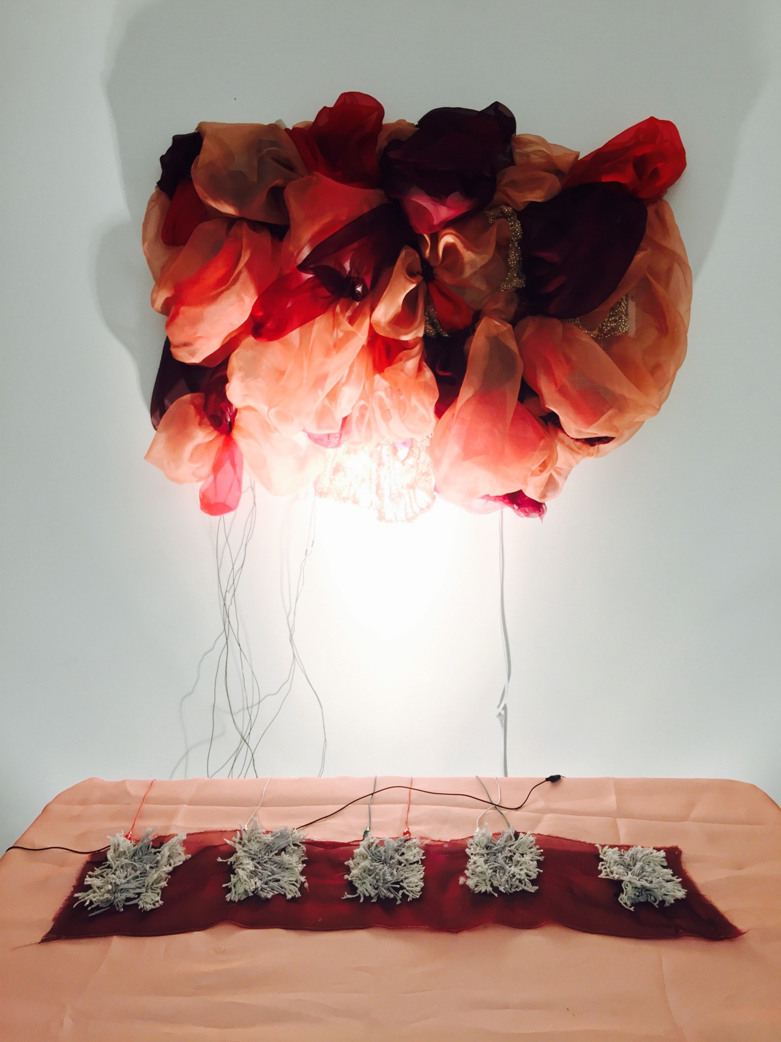
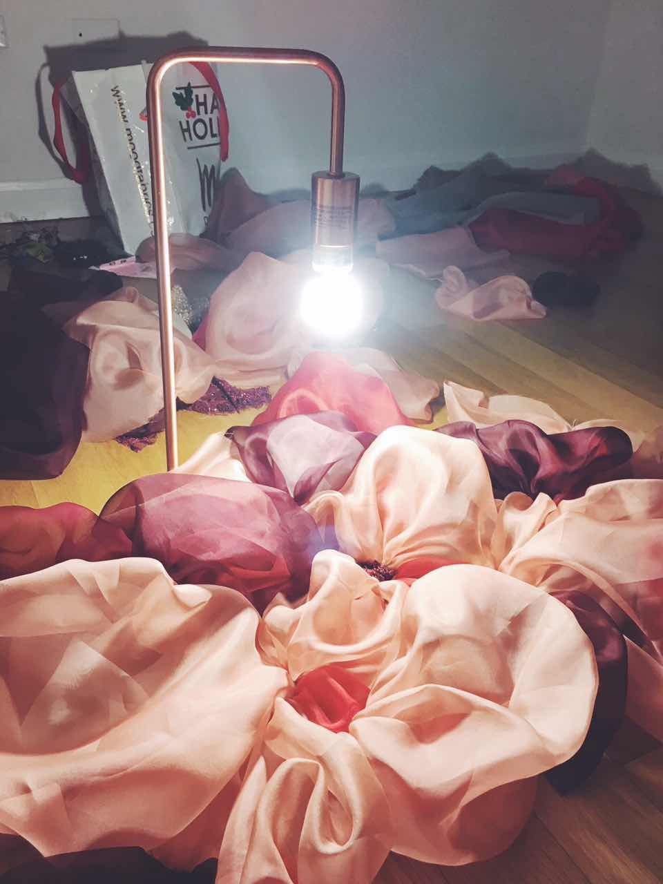
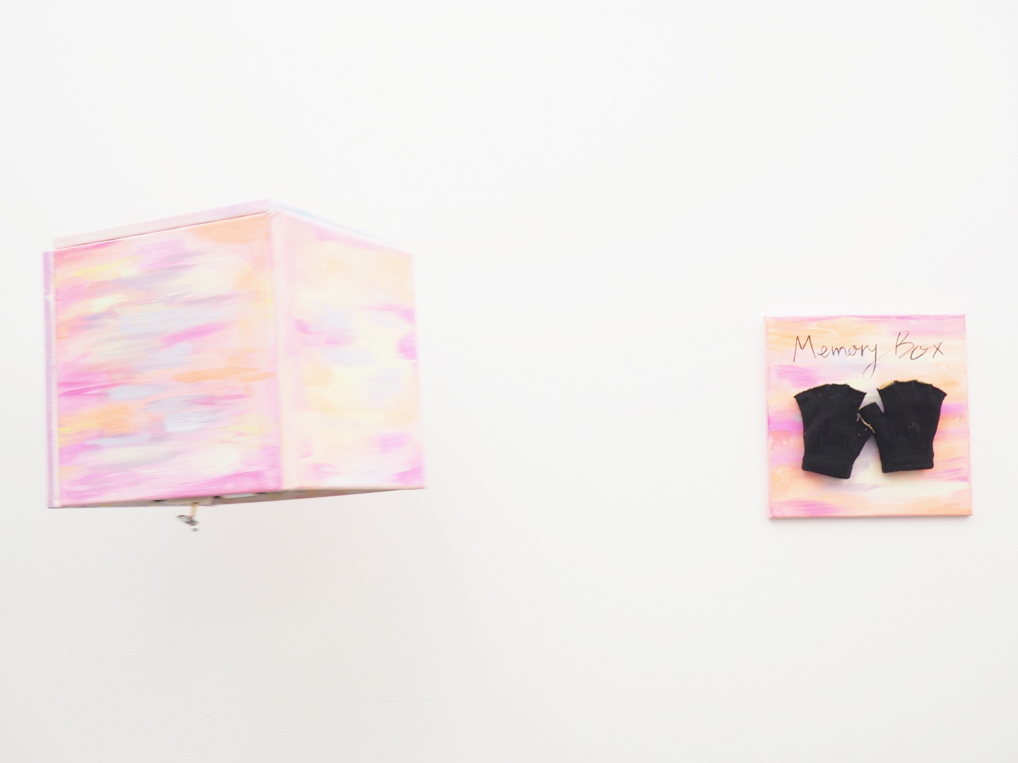
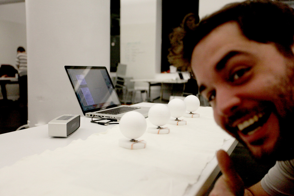
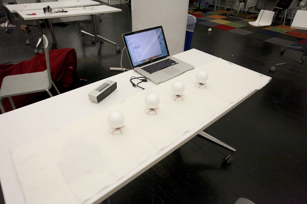
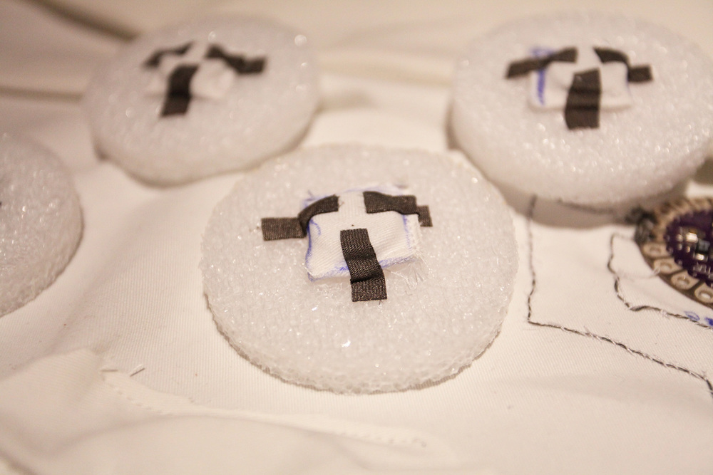
A memory box for people who need to be reminded of their beliefs and identities. When a person touches outside the box, the sound and voice will play by showing the images from their memory on what they want to be reminded of. During a person listens to the sound and voice in the box, the images on the memory box will fade away. That means the images are being absorbed as memories to the person.
Final.Video LINK
Instructable.http://www.instructables.com/id/MemoryBox/
Process.IMAGES
Reflection + Feed back
We enjoyed working together and were happy with our project in terms of both the technical and aesthetic aspects. In the case of technical aspects, using themocromatic pigments and the sound module worked well.
The one thing we felt not entirely satisfied with was the fact that color changes were insufficient because we might have used too many colors, but this was intended for our concept. Each person has various individual memories to be reminded of, and we tried to represent this visually by using different colors and action paintings to represent passing by many different memories.
Actually, we were thinking about using a distance sensor so that people can hear their memories automatically, not by pressing the button to turn on the sound manually. When someone comes into the space, it would be ready to play, and then it would play when the user touches the dome. However, everything with our project worked well. All the speakers were connected perfectly and the user heard sound when the user played with them.
We got feedback from a student in Paris. We got helpful questions for the future implementation such as how the memory box would recognize a specific person, in terms of the shape of the box, and the way of showing memories. We’ve decided to show the memories with abstract paintings, not specific images using a projector, but if we combine projecting images with paintings, it may be interesting.
I’m very happy with the outcome of my object and excited about moving forward with some of these techniques, having learned what I have from this process.
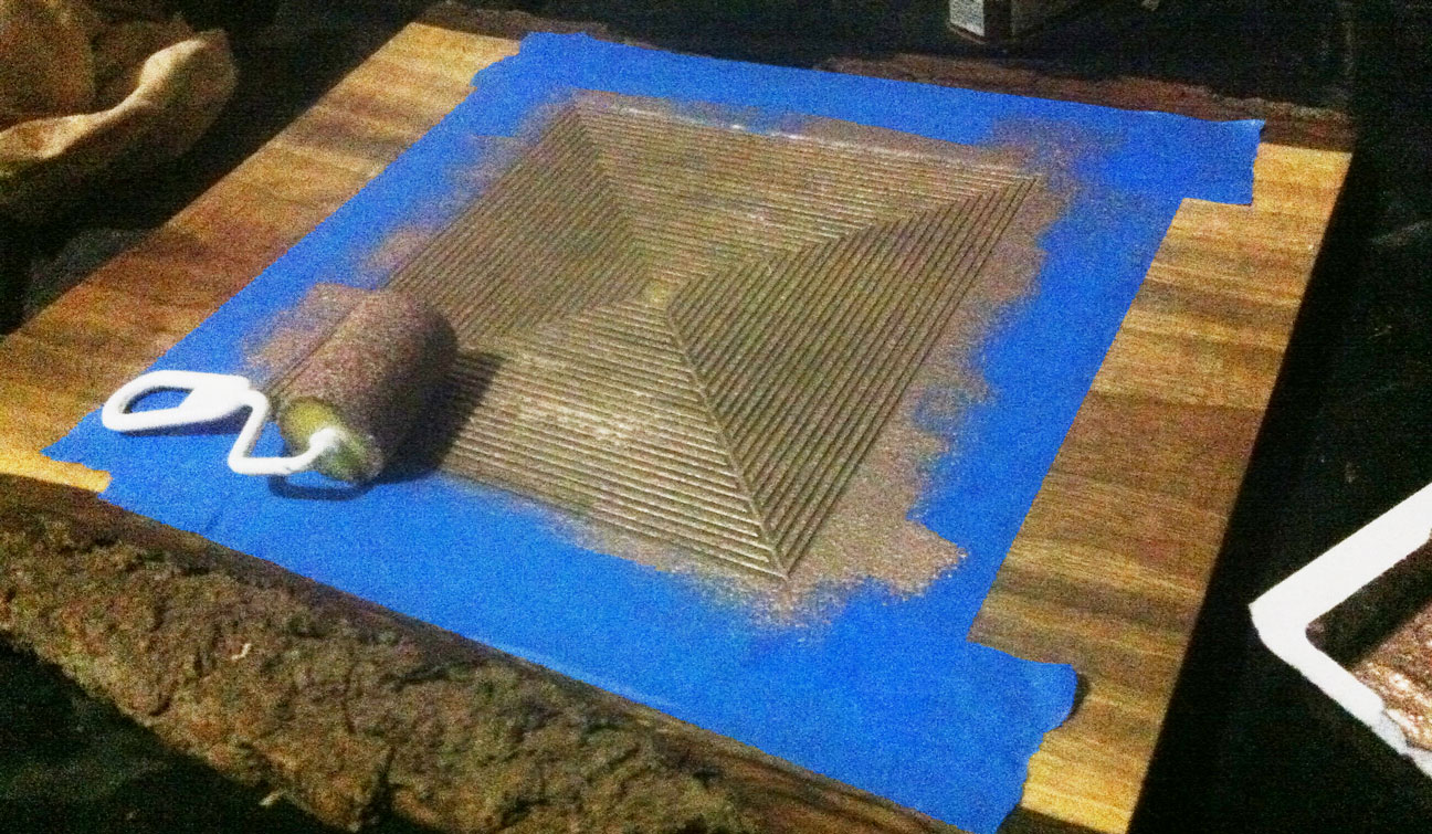
There was an initial setback after covering the area in copper paint with the foolish idea that I would be able to gouge out channels in the grooves to establish the circuit. After deciding this would be impossible I opted instead to sand off the top using the copper in the grooves as the active component.
From there forward, things seemed to work quite well and I had an interesting time trying to craft a piece of generate code to match the style and type of interaction with the object.
The instructable can be found here https://github.com/mjglen/CreativeCoding_oF_F15_Michae_Glen/tree/master/3dparticlemesh_project3
http://www.instructables.com/id/Mystical-Geometric-Slab/
The mandala like source code I wrote can be found on my github here http://www.instructables.com/id/Mystical-Geometric-Slab
A little demo video here (in case you missed the presentation)

The intructable is here,
CONCEPT
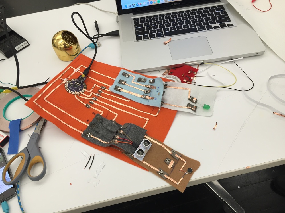
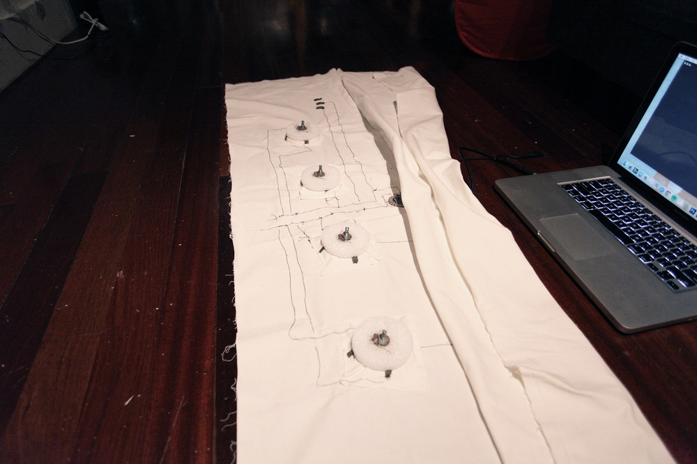
It’s a drum machine fabricated in a piece of fabric. It’s an exploration in soft circuit and new instrument. I wanna create a new drum machine that helps musicians (users) break through their habits to create music.
This drum machine is a brainstorming tool for musicians to create new sequence patterns quickly for their creations. Besides knobbing each modules to trigger sounds, they also can switch the modules for making new sequence.
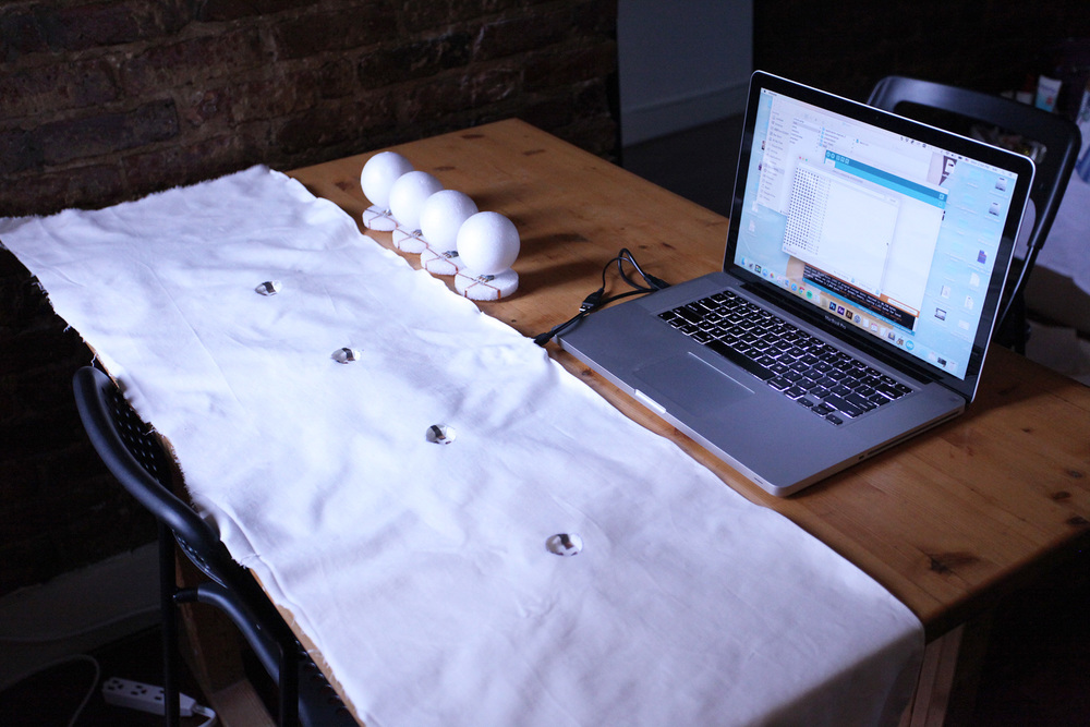
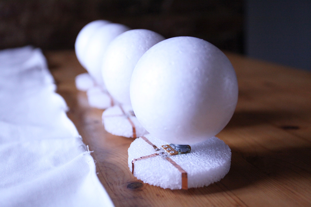
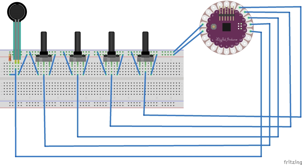
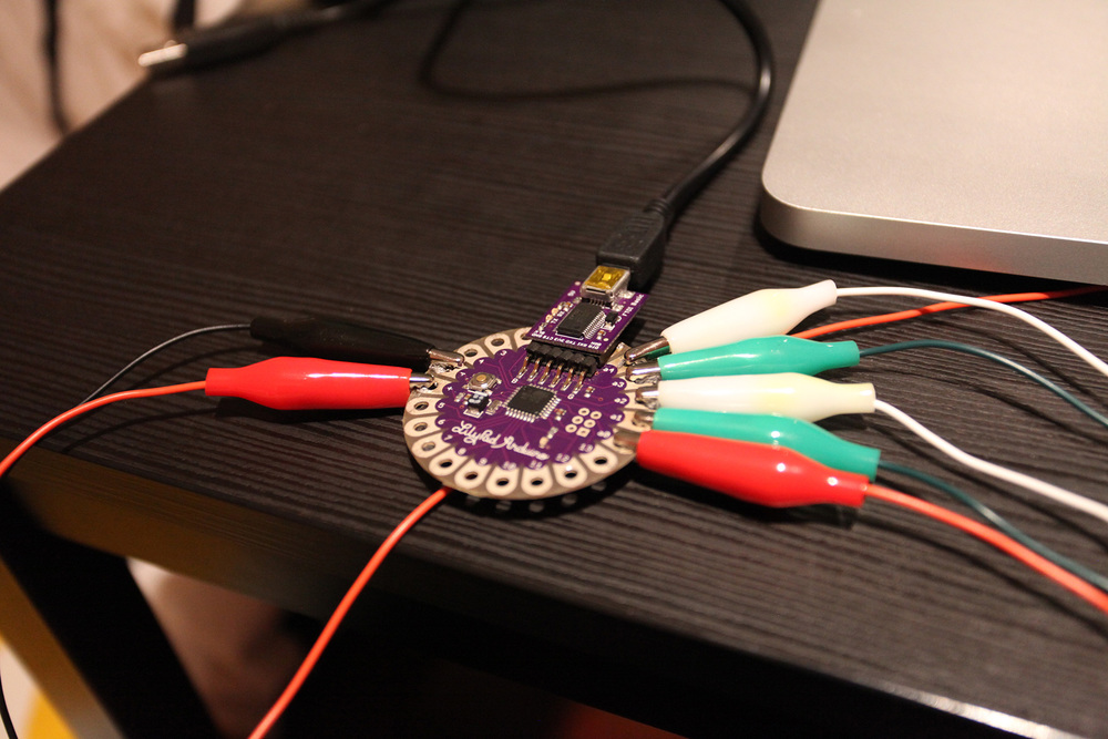
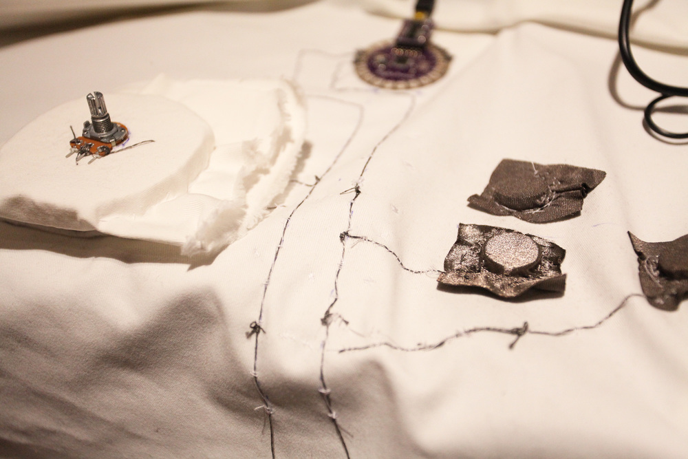
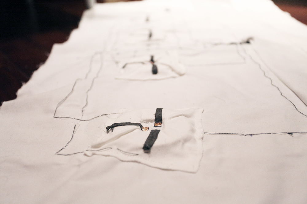
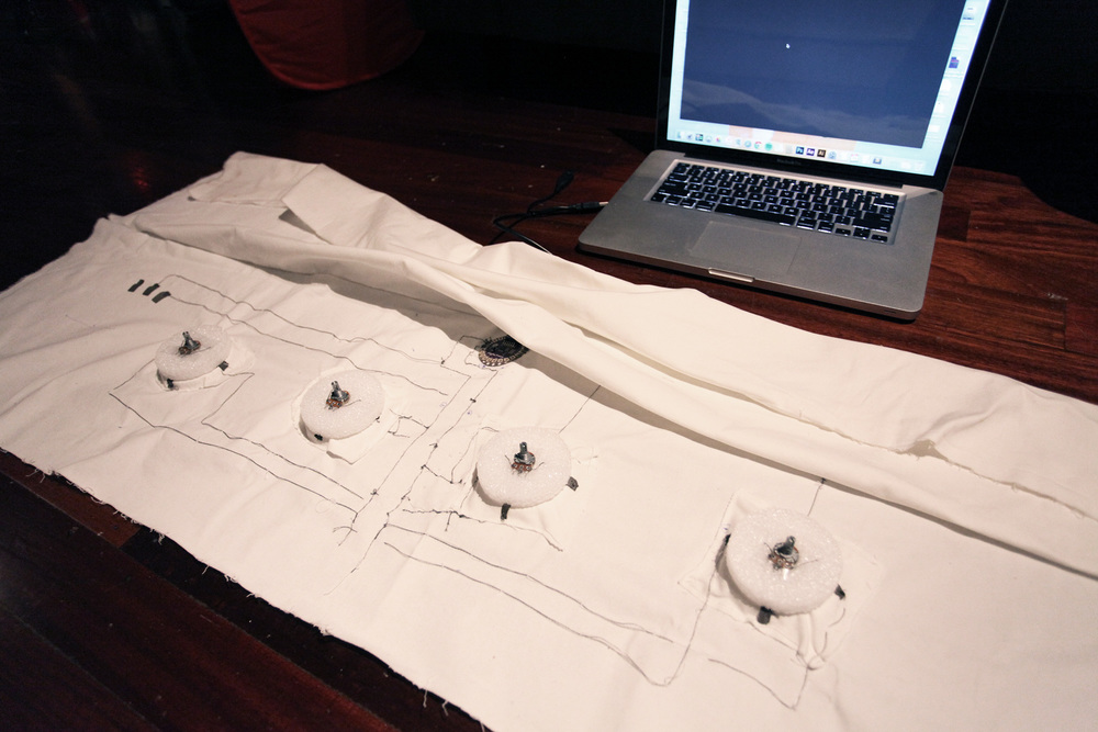
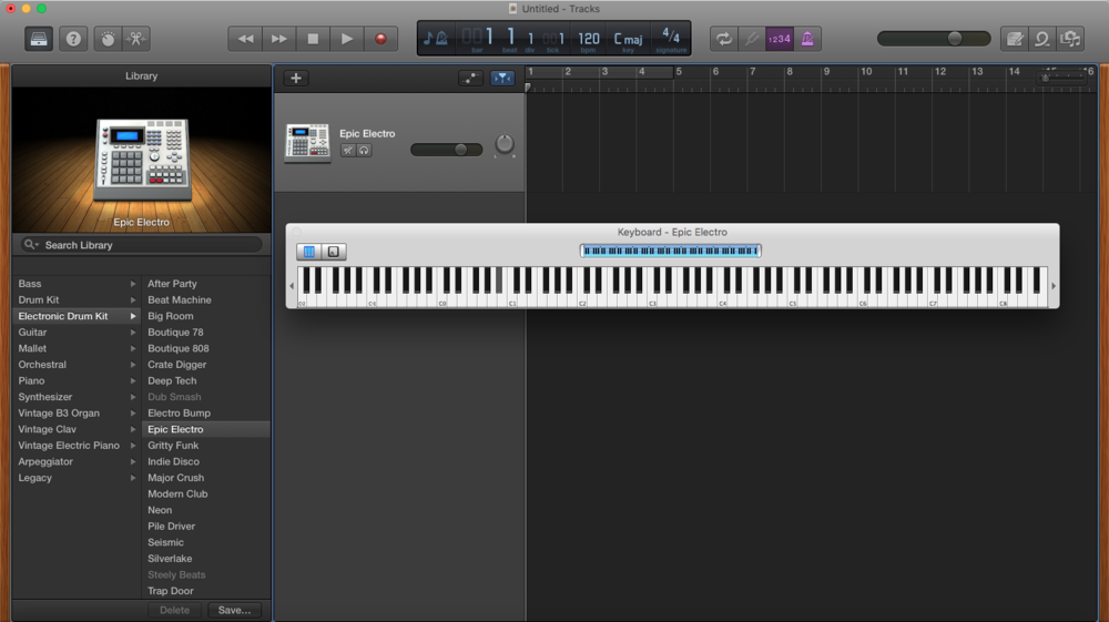
For the technology part, there are 4 potentiometers and 1 press sensor cooperating through Lilypad Arduino. Each potentiometer connects the main circuit by magnet. Arduino can send signals to GarageBand for creating sounds. This drum machine can loop sequence of sounds. By knobbing potentiometers, it can change different sounds in each position for creating new sequence patterns. By pressing press sensor, it can switch the 4 sounds to another 4 sounds. We even can pull potentiometers out from the main circuit and put them back to different positions for making new sequences. So it can help us create more different sequences for fresh music.
FEED BACK REFLECTION
I got critiques from Dasha, a student from Artisanal Tech in Paris. Her critiques are useful for me. We have similar ideas. When knobbing potentiometer, the pitches of sounds can change. I finally fulfilled this in my final piece.

CODE IS HERE, https://github.com/pekingkc/fabricDrumMachine
I also download a MIDI serial software for Arduino sending signals to GarageBand from here. It’s just like a bridge for Arduino and GarageBand.
RELATED PROJECTS,
http://www.dkaib.com/new-index/#/new-page-26-1-1/
http://www.dkaib.com/new-index/#/55839b3ce4b0a7f245ebc1ca/
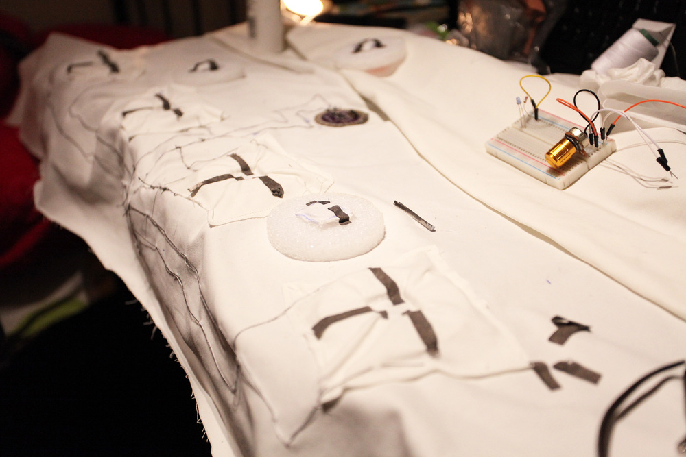
DOCUMENTATION OF PROCESS
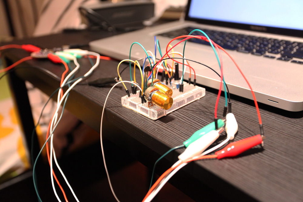
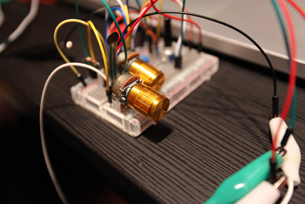
The video below is testing the function part on breadboard.
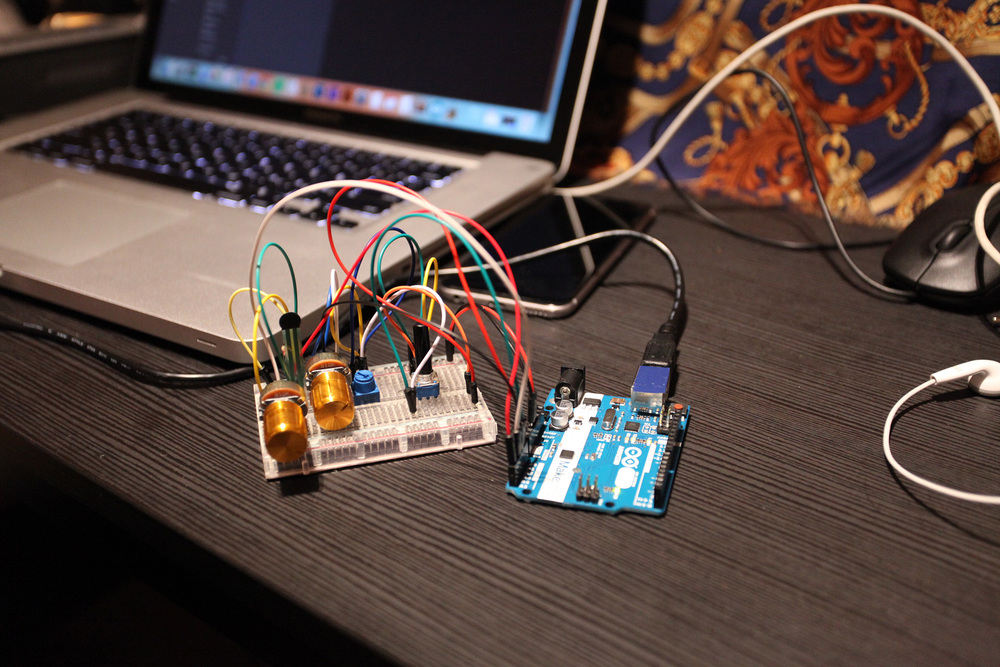
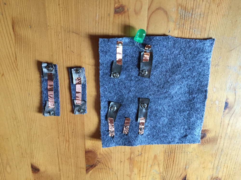
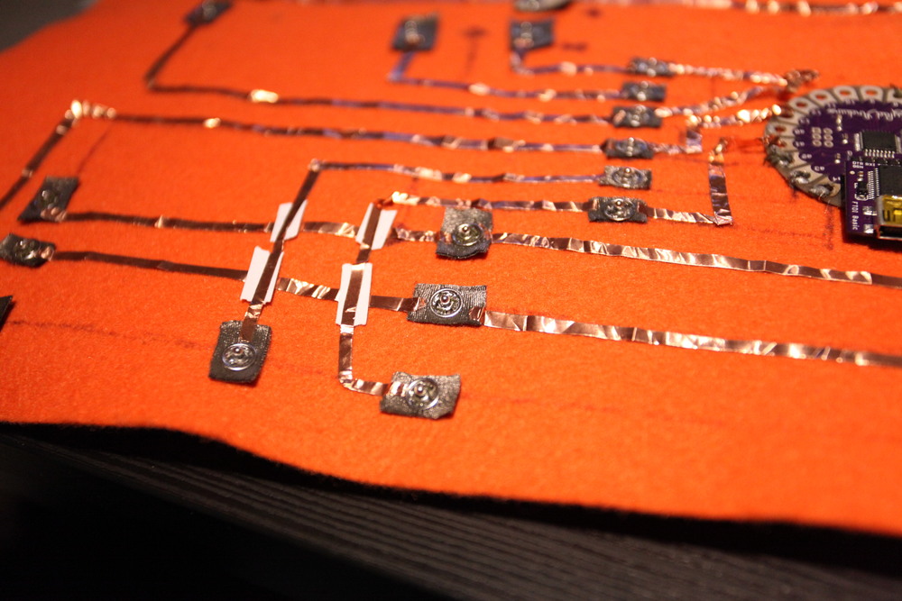
Testing connection on soft circuit.
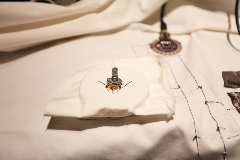
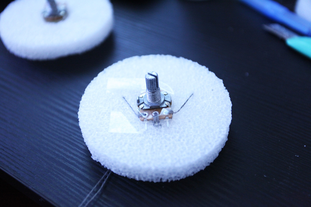
Testing the potentiometer on soft circuit.
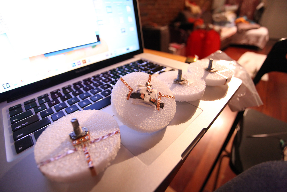
I tried 3 ways for connecting potentiometers with the main circuit. Finally I find the most suitable one in my 3rd prototype.

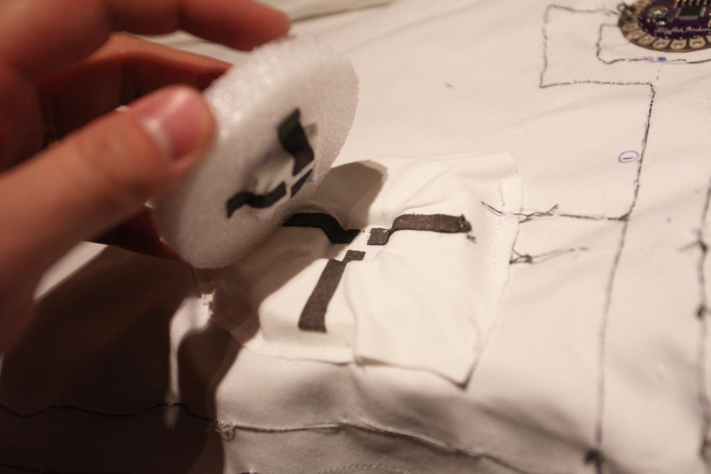


I choose magnet for connections, because it is easier to pull out and put on. I have tired using snaps for connecting circuit in my another project. But snaps are more hard to pull out which is not convenient for this project.
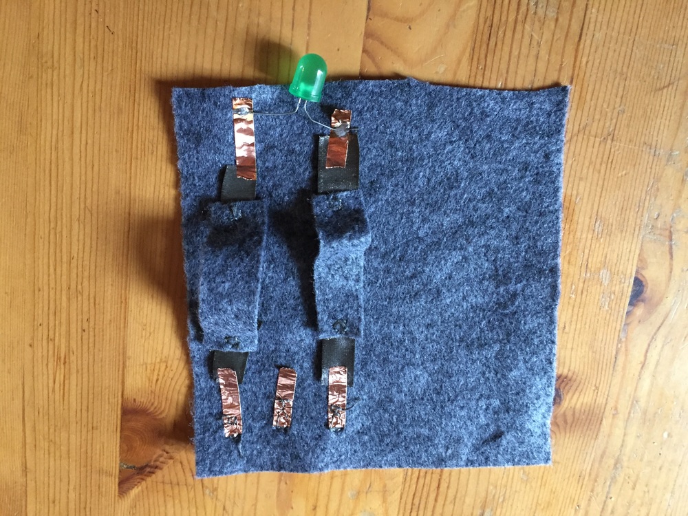
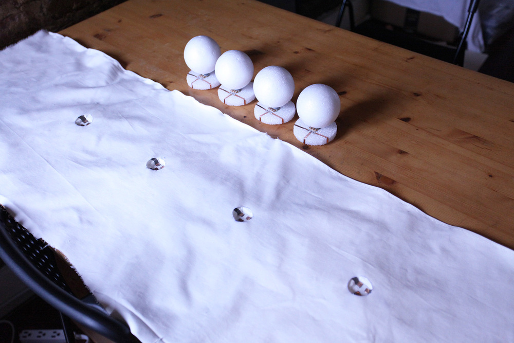
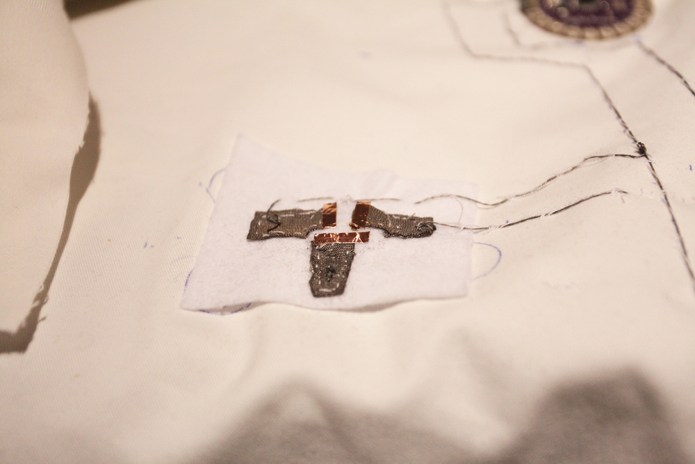
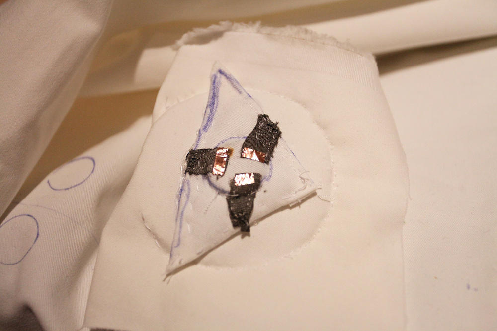
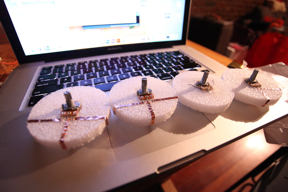
Making potentiometer modules and putting them on the main circuit.
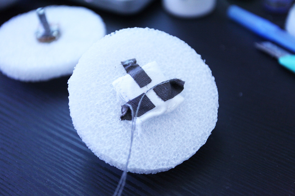
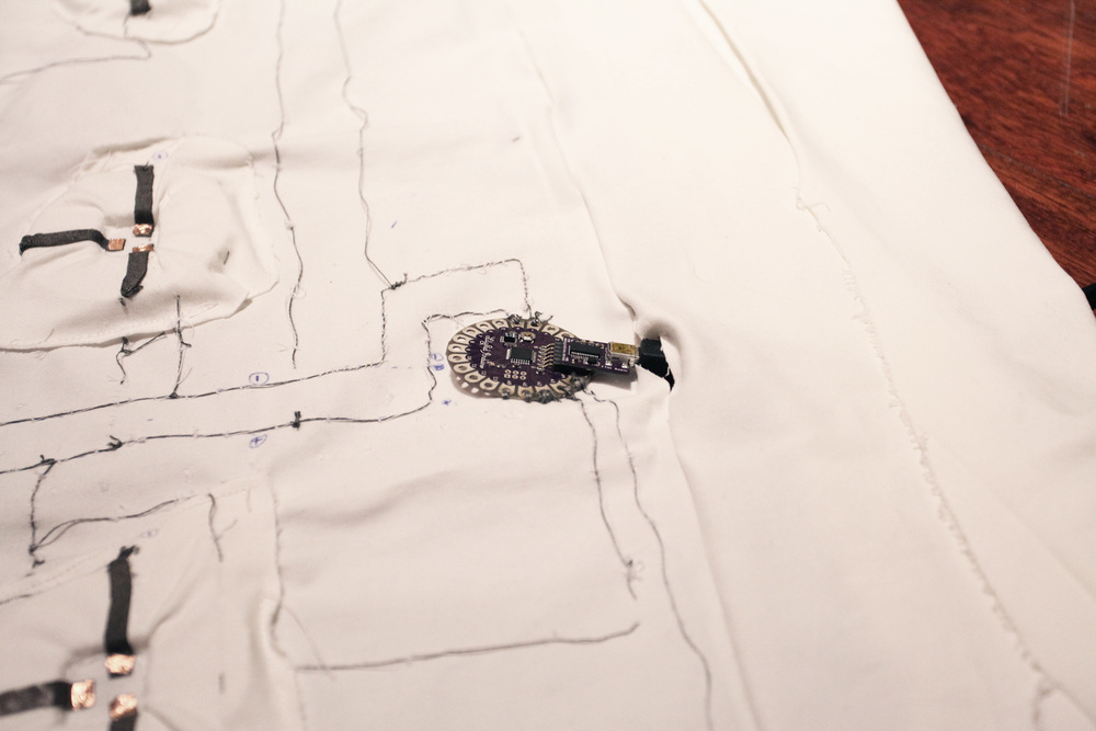

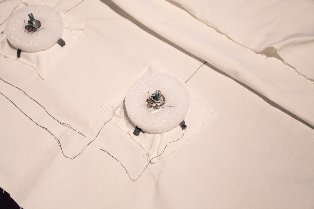
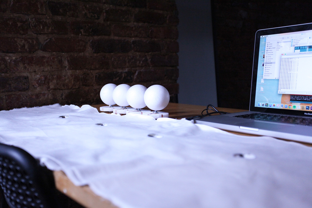
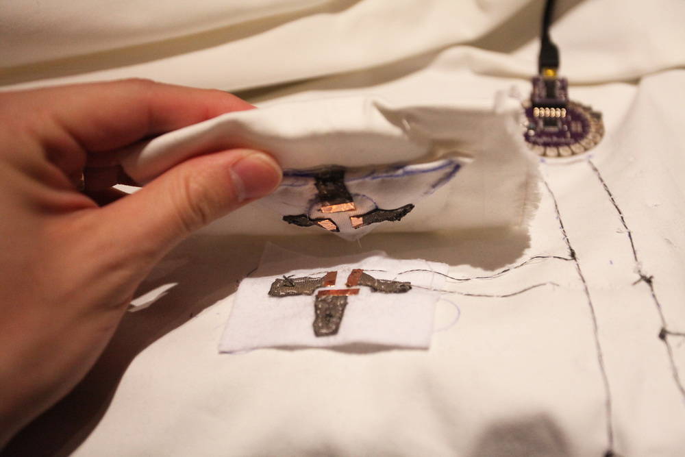
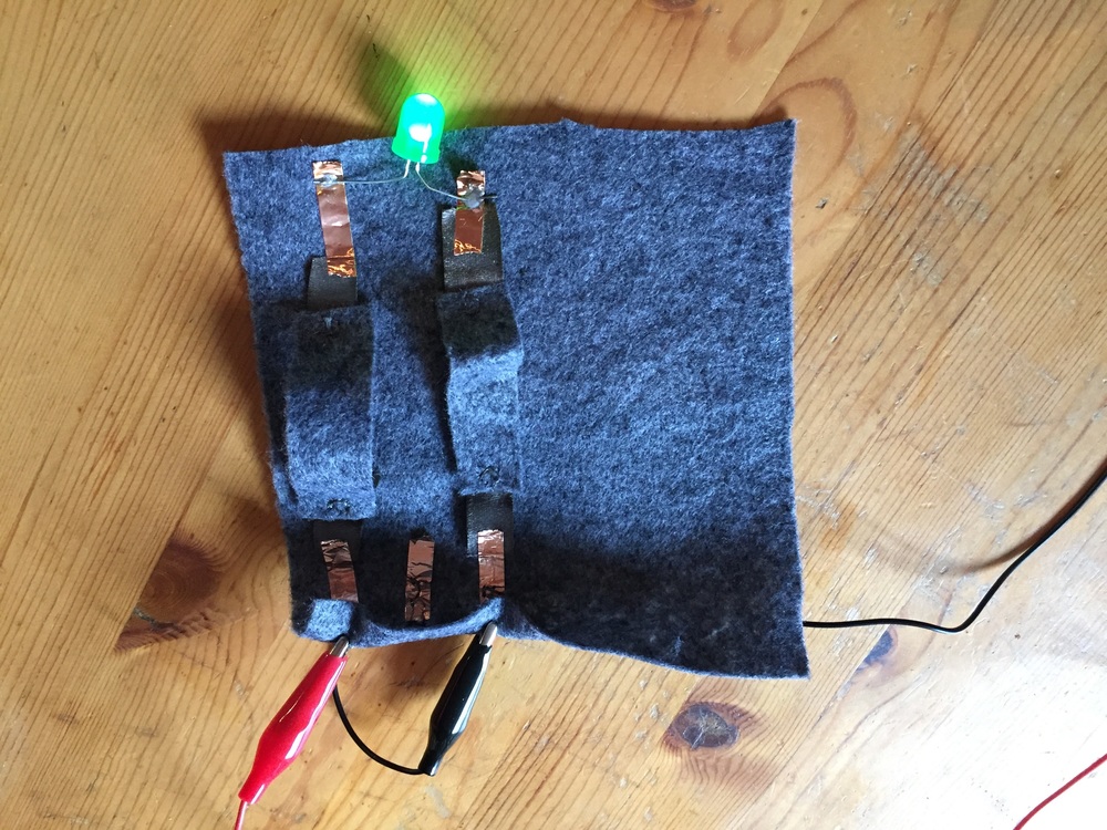
When done the main circuit, I connect modules on. The drum machine basically works.
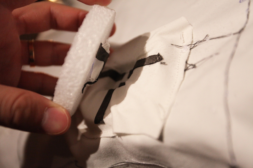
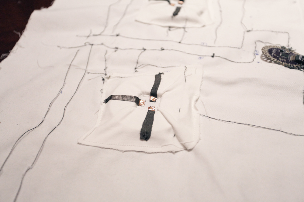
But as I use conductive thread to connect potentiometers, the threads in different holes on potentiometer often touch each other. It makes the modules work awkwardly. I can’t have the value I should have when I rotate the potentiometers. So I use copper tape (conductive) instead.
I also connect a press sensor, which is made by myself to the main circuit. Later when I press this sensor, I can switch to another 4 sounds.


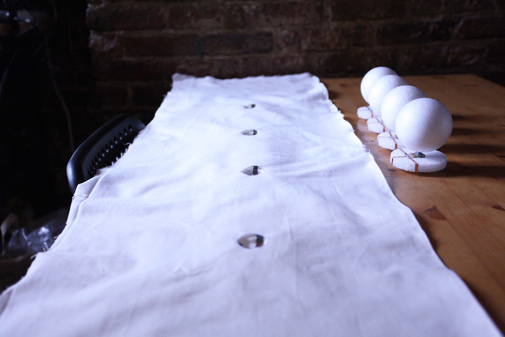
When all set, I seal the circuit with a cover leaving holes for connecting modules.


I choose Epic Electro in GarageBand for triggering sounds.
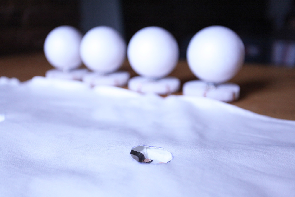
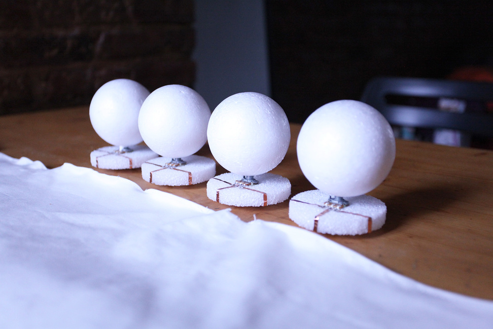
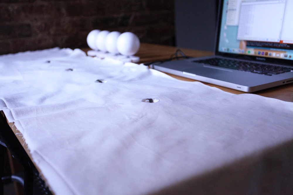
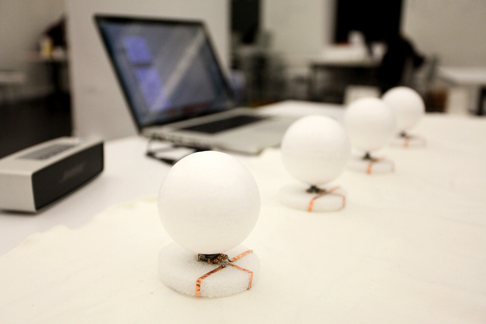
A series of sound sculptures with each having a sound and tactile manifestation of a stanza from a poem called Loteria (referring to the Mexican bingo game).
Sound Sculpture 1: El Nopal
instructable: link
Let whoever reads this understand
that when the desert took me,
it left me with only a lighter
and a friend.
Experience: As participant touches the needles around the cactus, the sound plays the stanza
Video:
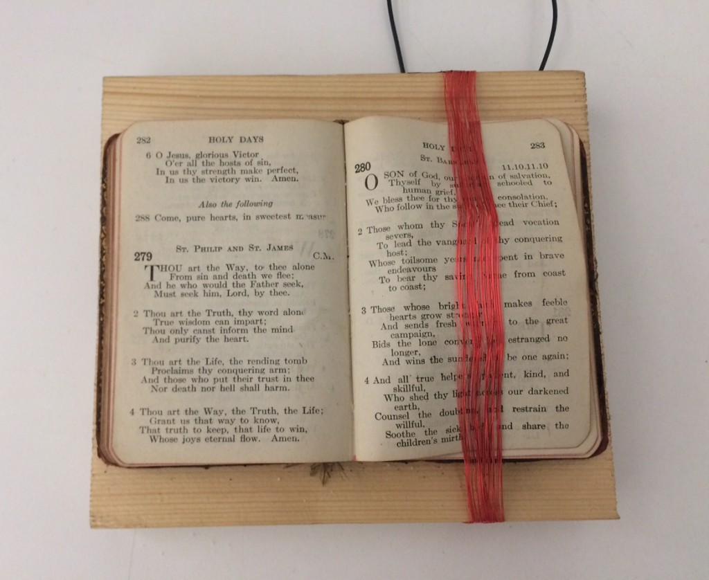
Sound Sculpture 2: El Musico
The guitar was called Mojave.
It had 10 strings with 4 broken.
The perfect sound to reverberate against
an audience of sand.
Experience: As the participant gets very close to the book, he or she can listen to the stanza
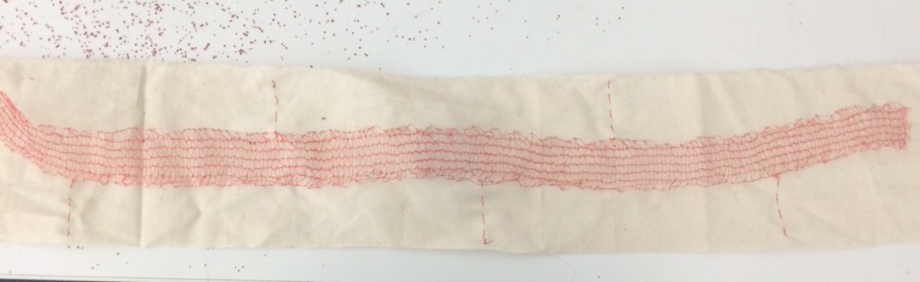
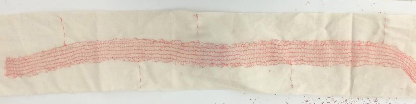
Sound Sculpture 3: El Alacran
I found one of the Milky Way’s spiral arms
embracing a small ranch in Tapalpa.
In the darkness I heard two scorpions dancing, singing,
We have not been before, and we will not be again.
Experience: As two or more people touch the edges of this very long knitted copper wire, the speaker plays the stanza
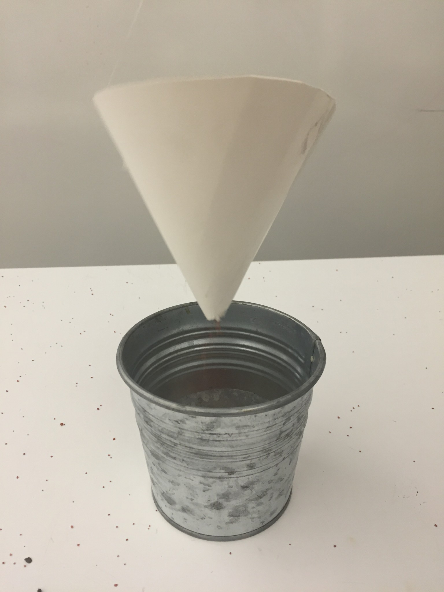
Sound Sculpture 4: La Pera
I watched a man choke on a pear,
and hoped for 6 or 7 minutes
that someone else would help him.
Experience: As sand goes through, the speaker is playing the stanza that is coming from the pot, the more it gets filled the harder it is to hear it