Author Archives: P.Feng

[Finals] Traces: Sometimes Things Just Don’t Work

I was inspired by the double pendulum’s random patterns to create something that would capture its patterns randomly for my finals:

2015-11-28 14.26.21

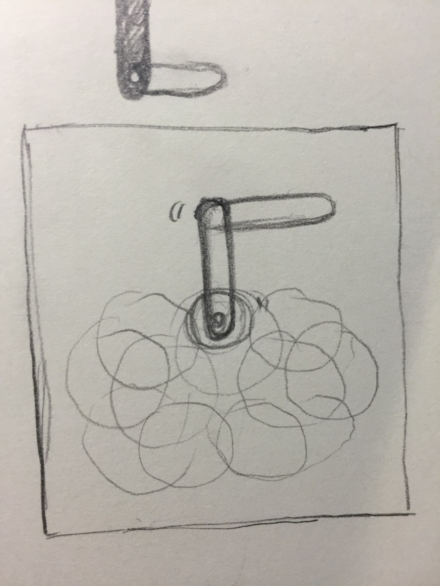
The concept was theoretically simple: I would use a stepper motor and the Easy Stepper Driver from Sparkfun to drive the pendulum, and I would draw the patterns on thermochromic ink with a heating element attached to the pendulum to trace its motion temporarily. All of this would be controlled using a Arduino Pro Mini, though at the beginning, I used an Arduino Uno to prototype.

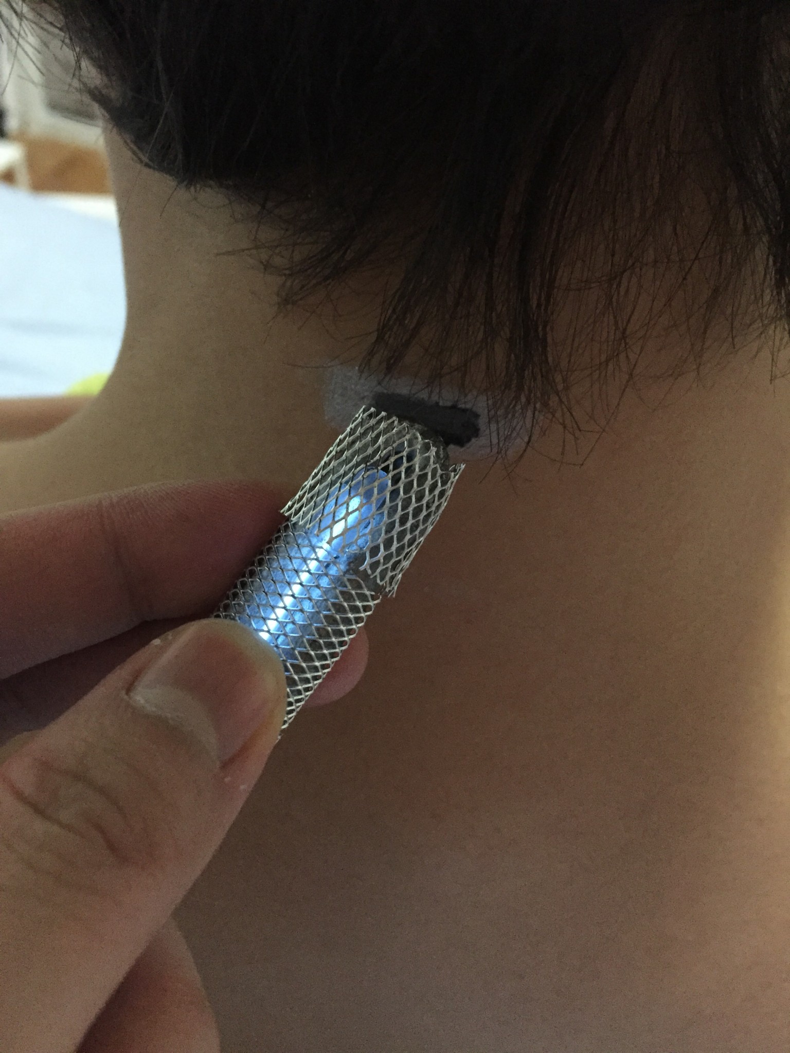
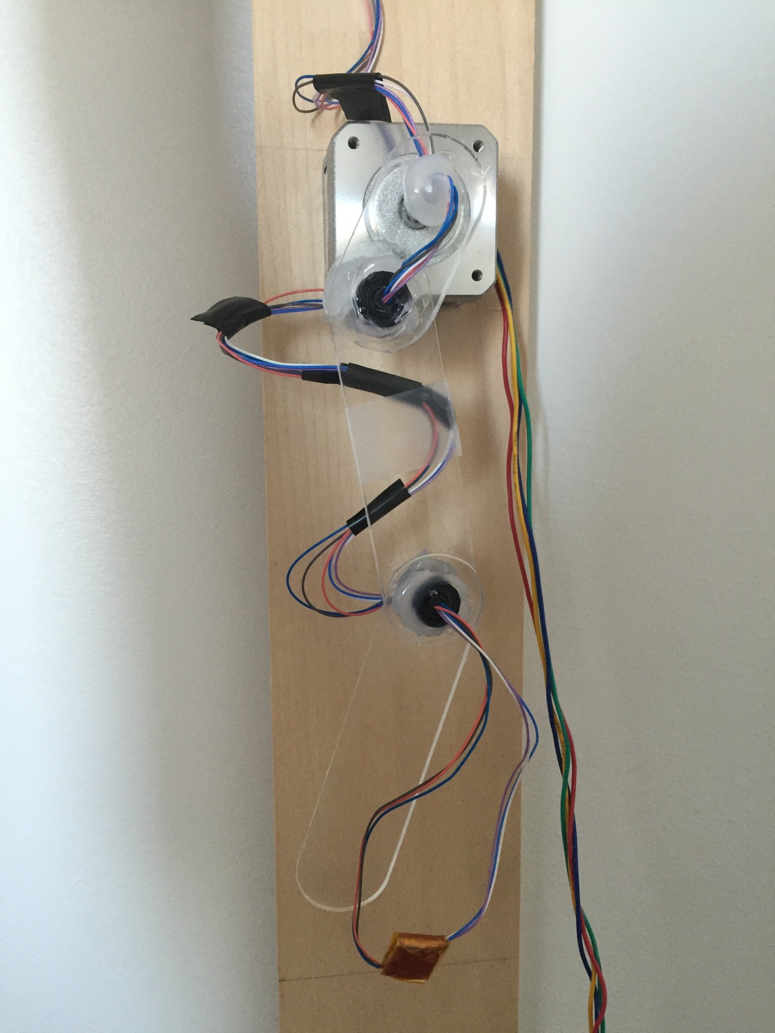
I powered the motor and driver from Sparkfun using a 12V/1A power source since at first I couldn’t seem to find any concrete information about what kind of power source to use with the driver. I laser cut the pieces for the pendulum from plexiglass and used a slip ring and glue gun to hold them together. The slip ring worked great to wire the heating element at the tip of the pendulum while still allowing for it to swing. I only wished the wires were thicker because the thin ones were flimsy and kept breaking, however, soldering three of them together to create one worked relatively well.

2015-12-15 13.21.47

The circuit I used for the heating element is the one found off of How To Get What You Want:

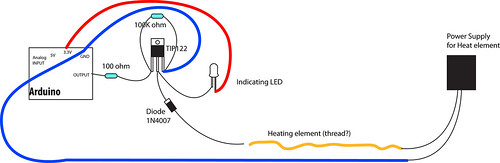
Instead of using the TIP122 transistor though, I used a TIP120 transistor, which according to its spec sheet, can handle up to 60V/5A of power. Throughout working on this project, I used a 9V/1A wall adapter and a 12V/1A wall adapter, and I also briefly tried using a 18V/1.5A battery which I’ll talk more about later. For the heating element, I originally wanted to use flexinol, however it burnt out too easily and its ability to move was a hinder in this case. After some research, I decided to use nichrome wire wrapped between layers of kapton tape for my heating element with much better results.

2015-12-15 13.22.41

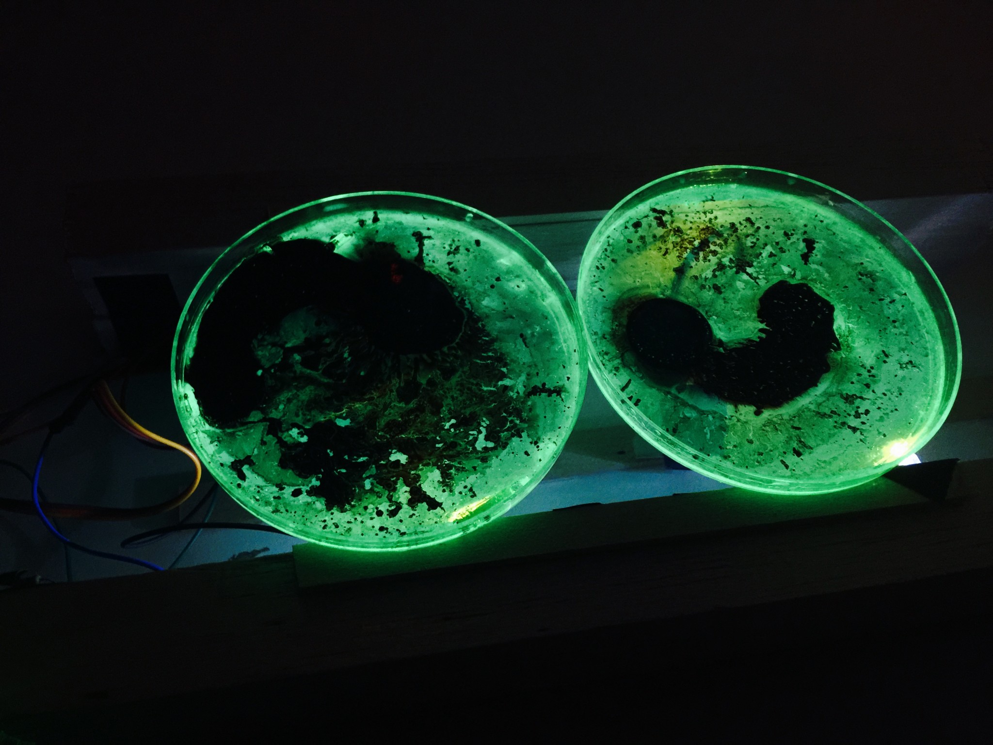
For the “canvas”, I mixed black thermochromic pigment with acrylic fluid matte medium binder, so that when heat was applied to it, the black would fade to an opaque white. Originally, I wanted to spray it onto a large sheet of plexiglass, however, the paint was too thick to go through the spray paint bottle, so I resorted to dabbing paint blobs onto the surface, which resulted in a interesting texture. 2015-12-26 11.34.41

I then built a frame around the plexiglass to which I would attach the motor with the heating element attached to it.

2015-12-26 10.38.42

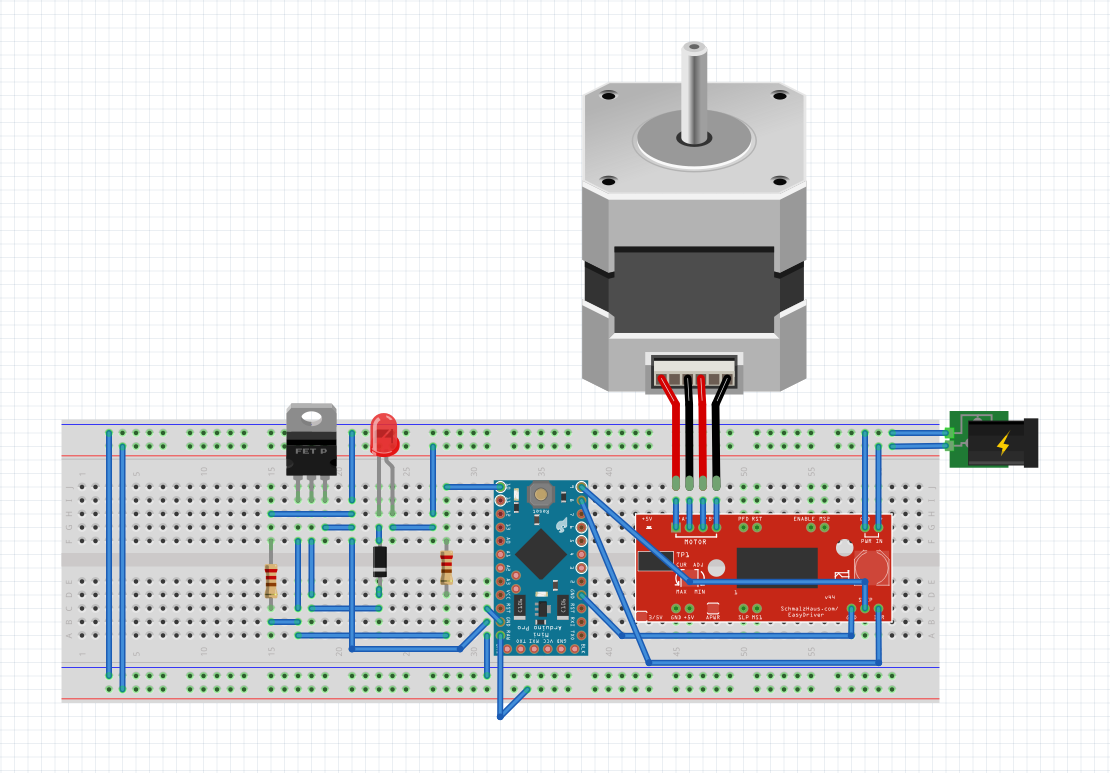
I then soldered the circuits for the motor and heating element together with the Arduino Pro Mini, to run off the same power source (12V/1A). The circuit looked somewhat like this (the heating element is where the red LED is):

Screen Shot 2015-12-26 at 12.14.35 PM

The code I was using:

const int DIR = 8;
const int STEP = 9;
const int HEAT = 10;

int distance = 0;
int heatState = LOW;
int stepState = LOW;

unsigned long prevMillisHeat = 0;
unsigned long prevMillisMotor = 0;
unsigned long prevMicrosStep = 0;
unsigned long currentMillis;
unsigned long currentMicros;

long heatInterval = 5000;
long motorInterval = 1;
long stepInterval = 100;

boolean running = true;

void setup() {
pinMode(DIR, OUTPUT);
pinMode(STEP, OUTPUT);
pinMode(HEAT, OUTPUT);
digitalWrite(DIR, LOW);
digitalWrite(STEP, LOW);
}

void loop() {
currentMillis = micros();
heat();

if (currentMillis – prevMillisMotor >= motorInterval) {
prevMillisMotor = currentMillis;
if (running == true) {
motorInterval = 1000;
spin();
Serial.println(distance);
if (distance == 2000) {
if (digitalRead(DIR) == LOW) {
digitalWrite(DIR, HIGH);
} else {
digitalWrite(DIR, LOW);
}
distance = 0;
running = false;
}
} else {
motorInterval = 2000000;
running = true;
Serial.println(“PAUSE ME”);
}
}
}

void spin() {
digitalWrite(STEP, HIGH);
digitalWrite(STEP, LOW);
distance ++;
}

void heat() {
if (currentMillis – prevMillisHeat >= heatInterval) {
prevMillisHeat = currentMillis;
if (heatState == LOW) {
heatInterval = 5000;
heatState = HIGH;
} else {
heatState = LOW;
heatInterval = 100;
}
digitalWrite(HEAT, heatState);
}
}

As a result, my project worked — for a very brief two minutes or so (which was not enough time to grab a camera to document this), before the power source blew. Wondering if it was just a wonky power adapter, I blew two more before I decided that there was something wrong. Exactly what though, I had no idea. Thinking that the 12V/1A adapter was not giving off enough current, I decided to try a 18V/1.5A rechargeable battery which burnt my nichrome wire into smoke and ash as soon as I plugged in the power source. 1.5A with my current circuit was way too much current, and produced way too much heat for the nichrome to handle.

Doing some more investigation, I found that Brian Schmalz (the designer of the driver) wrote:

  • M+ : This is the power input to the Easy Driver. Connect this to the positive power supply lead. This should be a 6V to 30V, 2A (or more) power supply that is clean (low ripple).

I have no clue how on earth I missed this! I think because I read the driver can regulate the current to produce 150mA – 700mA, that I thought that 1A would be enough to power the driver. I ended up buying a 12V/2A adapter and prayed it would work.

The problem now, is that 2A would be enough to fry my nichrome, since it’s way more than 1.5A. I had two options: use two power sources, or start thinking a little about physics.

If V = I * R, and E = V * V / R, when I used a 9V/1A power supply, I had roughly 9 watts of power going through the nichrome. For 12V/1A, I had roughly 12W. And 18V/1.5A which caused smoke was roughly 27W. Theoretically if I can keep the W down to ~12W, then I should be able to use 12V/2A. So if I added a 10 ohm resistor to one of the heat lines, that should keep it to roughly 9W of heat going through the nichrome. That’s my theory, but my physics was really, really dusty.

Since I was really short on time, I decided to rewire things to take on two power sources, with this circuit: Screen Shot 2015-12-26 at 12.41.27 PM

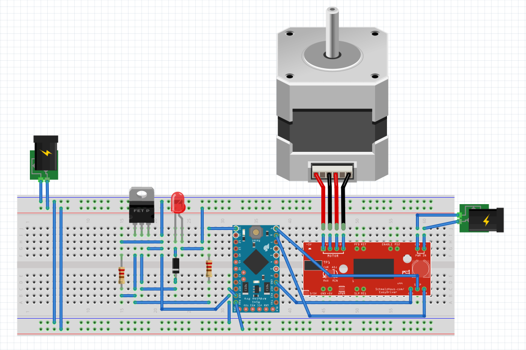
 So the motor no longer blew out my adapter, and the nichrome played nice when plugged in separately…. However, when I plugged in both of the power sources at once, the motor wouldn’t spin smoothly, if at all.

At this point, I’m at a loss and not quite sure what’s wrong with my project. So I’m going to accept the fact that some things just weren’t meant to work for the time being and leave it be. I’ll come back to it after some time with a fresh mind and hopefully I’ll figure out what’s wrong.

Instructables: http://www.instructables.com/id/Trace-a-Work-In-Progress

[On Paris]: Honestly, I thought the feedback was alright, but not very useful. It would’ve been great had it come a lot sooner, maybe if we were going back and forth since the beginning of the semester.

Bio-Memory Drive


In 2580, humans have increased their memory capacity by using drives that can be slid into a slot at the base of their necks. This slot is wired with the human nervous systems and their brains, taking in sensory input directly from the human senses. These mini drives can be removed and stored physically, or they can be synched with cloud services, literally with a thought. The files — memories, can be accessed by thinking of the thought, or whatever mental system the user has to access their files.

2015-11-28 15.23.18 2015-11-29 18.41.01

Finals Concept: Double Pendulum

I’ve been very fascinated about kinetic sculptures recently. I would like to create a “painting” that is created through mechanical methods, specifically using the double pendulum, which creates beautiful, random-looking patterns.

This has been done with LEDs before:

However, with LEDs, you can’t see the full patterns unless you record or photograph it. I would like to use thermochromic paint that would capture its trajectory long enough to be visual, but will disappear over time to start again.

2015-11-28 14.26.21

My two main concerns are how to blend thermochromic pigments with a medium that will allow it to go transparent and be able to spray it evenly onto acrylics, as well as how to wire the spinning arms so that the tips are heated only, but still allow it to spin without getting tangled.

Formless Beings of Light [Midterms]

By: Michael, Isabella, Cihang, Cathy

IMG_2471

The ability for humans to intervene within nature and redesign it for their needs, combined with the ability of this process to inform future designs represents an exponential relationship. As example: the capacity for technology to facilitate the development of further technology. If this process were to continue it would approach a limit of complexity termed the Singularity.

According to futurist Ray Kurzweil,

“The Singularity will allow us to transcend these limitations of our biological bodies and brains … There will be no distinction, post-Singularity, between human and machine”

We propose the question – In what manner would light be used in a world in which biology is transcended beyond physical form?

We speculate a distant future in which humans have transcended beyond the physical form of the body, though are yet to transcend the materiality of time and space. As such they exist as arrangements of information, in the form of energy suspended in an electromagnetic substrate. Despite the radical reconfigurations of form, the use of light energy is still the most effective means of communication and information transmission.

Within the Buddhist concept of Nirvana, when the passions of desire and ignorance are released the cycle of existence ceases. If such beings were capable of removing the barriers to omniscience via an exponential structuring of information, an analogous condition may be obtained in which desire no longer exists. Using this metaphor we can consider these beings to exist in a state of pre-enlightenment whose only remaining desire is that they wish to achieve a state of release from existence through full knowledge.

Week (3+4)

In Class:


Screen Shot 2015-09-25 at 12.02.40 AM


I was aiming to create a circuit that’s pull, using the magnets to pull the battery to the magnet to complete the circuit, but in the end, I think I ended up doing hit. It was fun anyway.

Video: https://youtu.be/QdbYMZTui_A

Hack-a-Keyboard: 

Screen Shot 2015-09-25 at 12.08.07 AM

Using construction paper, I folded an origami frog and added pieces of wire mesh onto it so that it would type a letter each time you made the frog jump. (Though my frog didn’t feel like jumping too much). I used this origami controller to control a game of Frogger. (Run in Processing with code by R.M. Watkins, found on openProcessing)

Video: https://youtu.be/YnqgVHSONKk

DIY-ing With LEDs (Week 2)

Class creations:

In-Class:

A multi-coloured DIY bracelet.

2015-09-08 20.39.09-12015-09-08 20.38.26


A mini-tiara with LEDs:


2015-09-08 20.59.15


For my illustration project, I used a haiku that I found:

Without flowing wine/How to enjoy lovely/Cherry blossoms?

– Anon.

The lights are underneath the illustration that has two power lines hanging out from the end. When the ends are put into water (or wine!), the lights light up, lighting the blossoms.

There are two pieces of paper that make up this, one that has the actual wiring and LEDs, the other on top of it is a slightly transparent piece of paper with the illustration. I wanted to use copper tape to do the wiring, but the copper tape I bought seems to be too thick or something, because they wouldn’t light up the LEDs, so I used the copper wire I had at hand. I also wanted to do more lights and flowers, but I broke most of mine trying to get them into place (those legs are fragile!).

When I tested it out with water, it didn’t seem to work, but then I put a ton of salt in the water and it worked well enough.

Link to video: https://youtu.be/qt_VS5B9HOA

Hopefully it will make its way to class in one piece.


2015-09-12 23.28.31


Lotus Dome by Studio Roosegaarde (Week 1)

1414-4598-image

Link to video (since it’s not inserting itself into the post): https://www.studioroosegaarde.net/project/lotus-dome/

From Studio Roosegaarde:

LOTUS 7.0 is a living wall composed of smart foils that fold open in response to human behaviour. When walking by LOTUS, hundreds of aluminium foils unfold in an organic way; generating transparent voids between private and public space.


LOTUS makes physical walls immaterial, giving way to a poetic morphing of space and people.


Specifications:

2010-2011. Curved wall of 4 x 2 meters fitted with hundreds of smart foils, lamps, sensors, software and other media.

Lotus Dome was the project that opened my eyes to the existence of smart materials. At that time I thought it was absolutely fascinating how materials could move on “their own” and still am fascinated its potential. Though I’d always known that logically, material is very important when it comes to creating something, especially installations, Lotus Dome really struck that home since the concept to it is quite simple, yet the results is quite beautiful, thanks to its use of materials. Since then I’ve always wanted to get my hands on some of these “new” sorts of materials, though so far I haven’t been able to, since they’re not exactly budget-friendly.