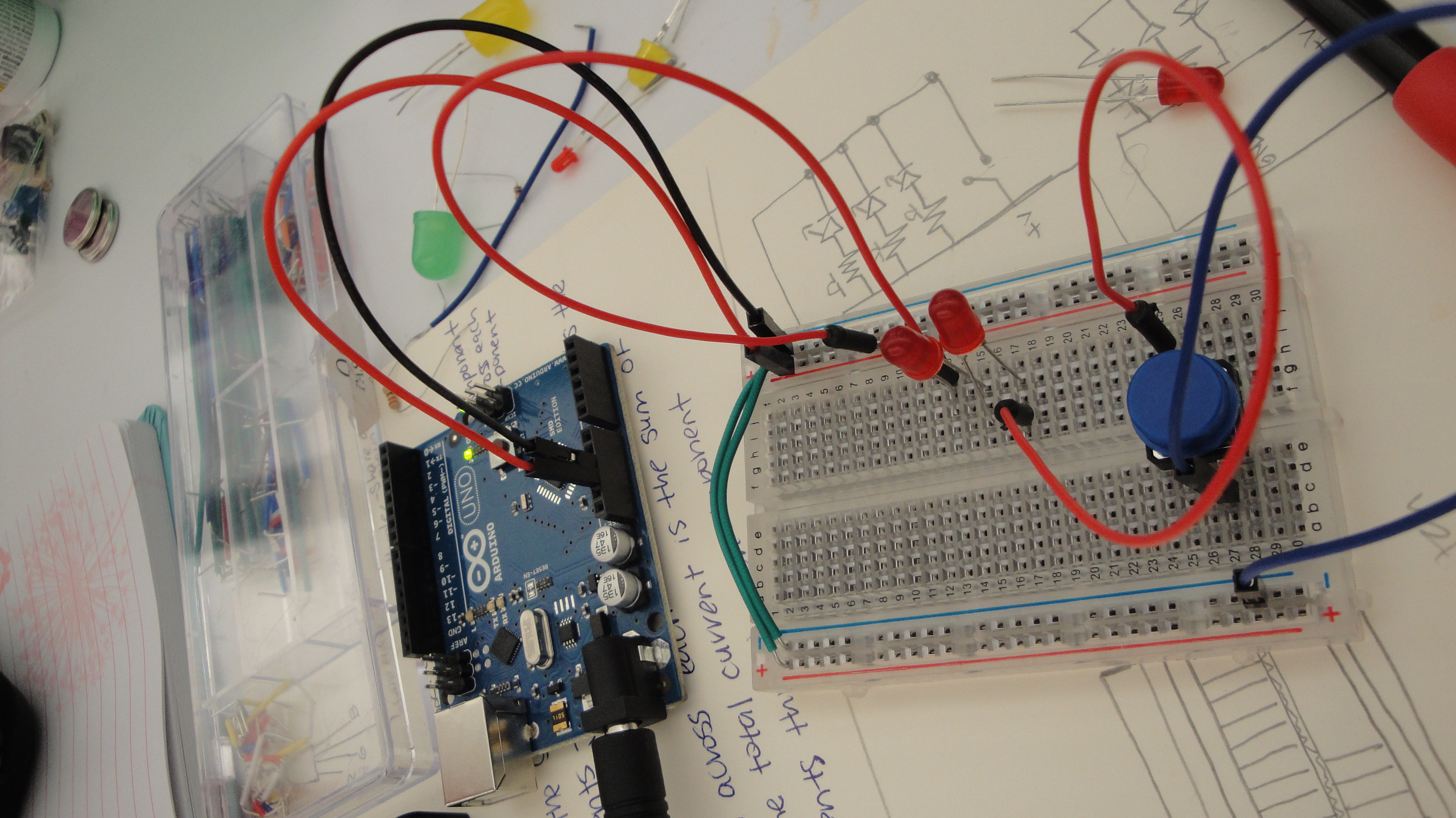
Here are my two circuits, their documentation (stills and video) and their calculations. Not sure if they’re all right, got a bit confused so looking forward to clarify this in class today. Had fun lighting things up though!
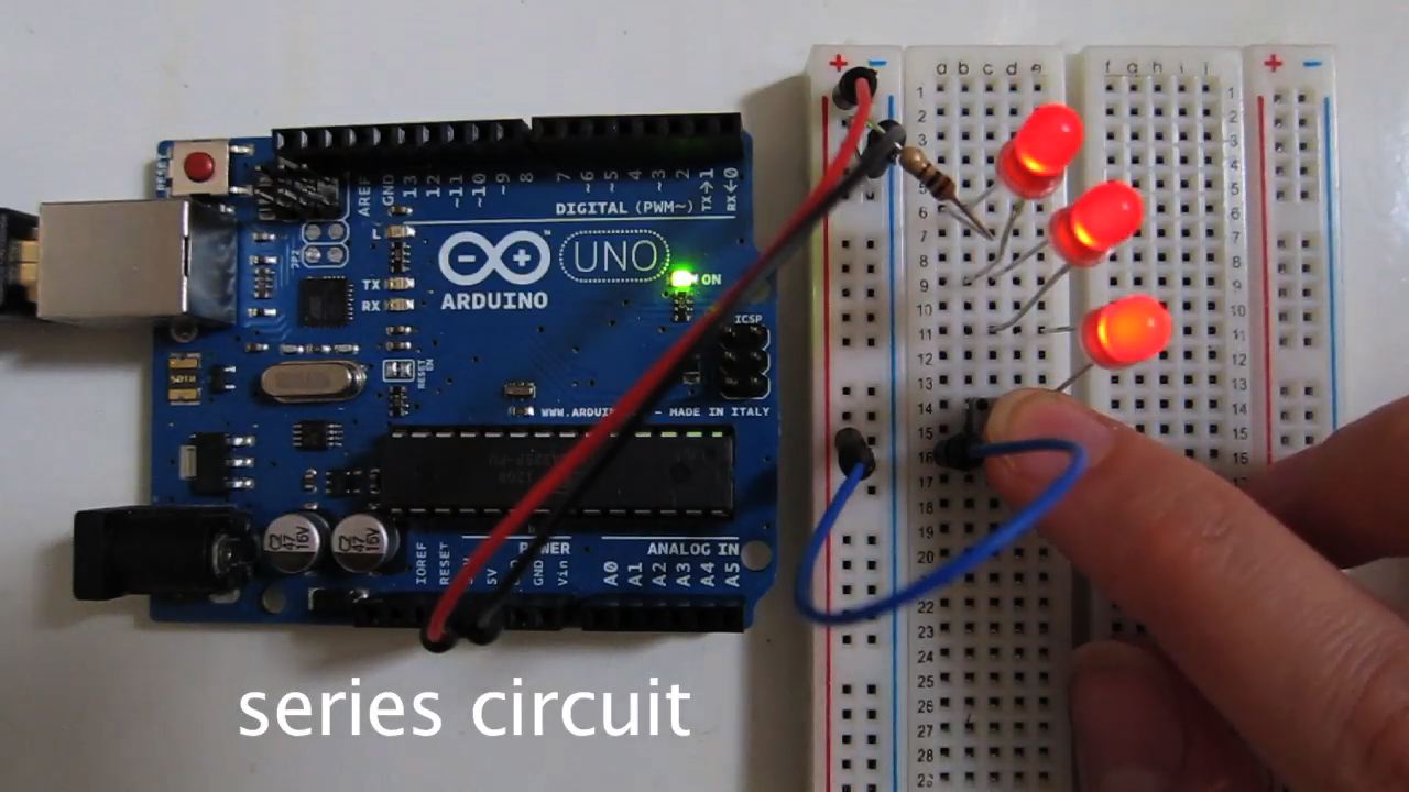
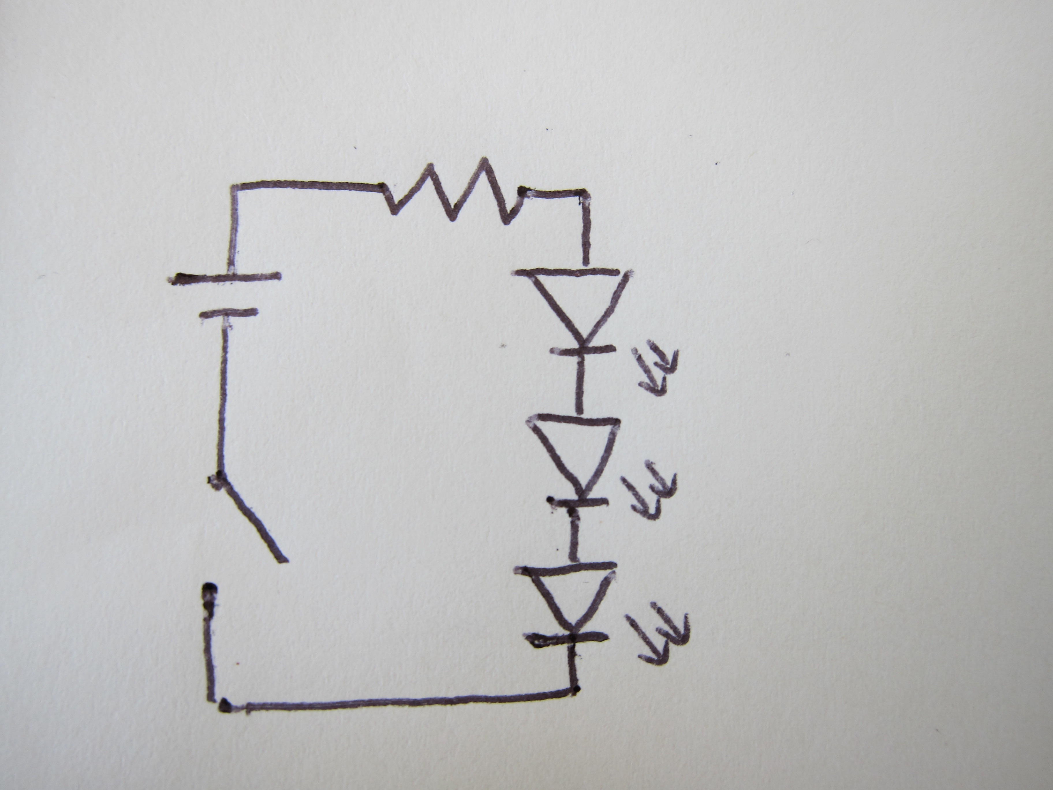
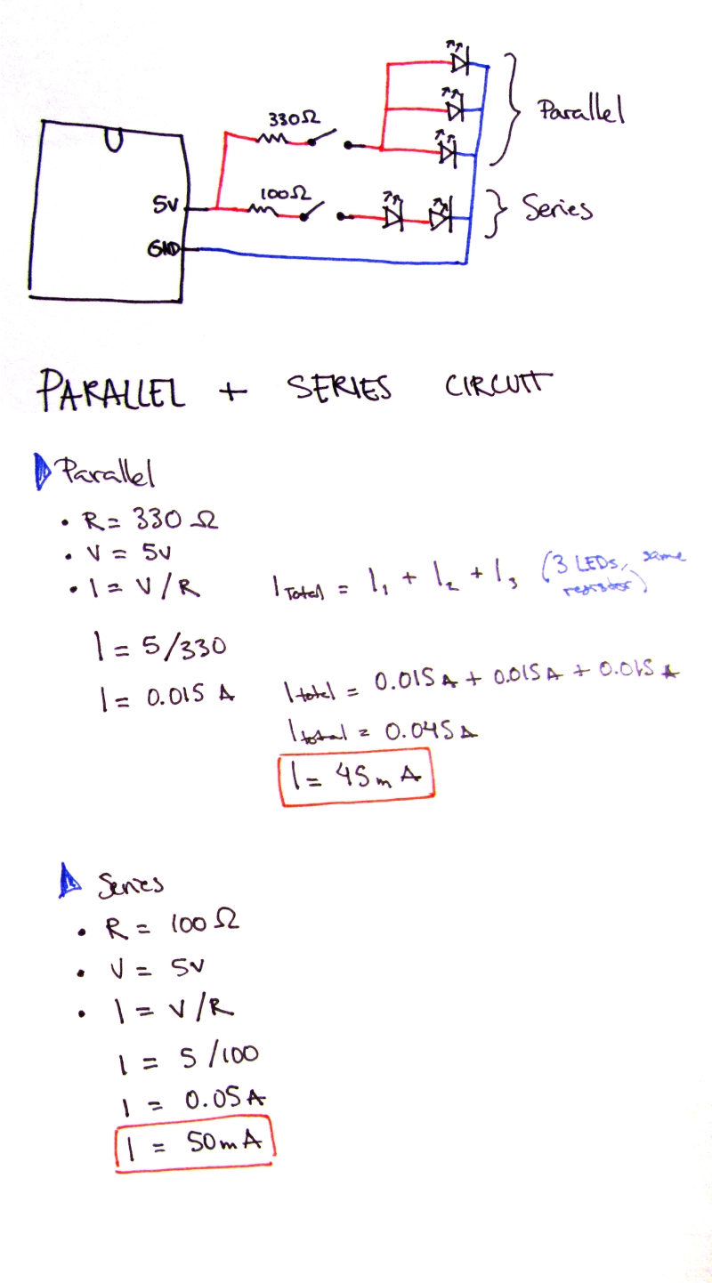
V = 5/3 = 1.666…
R = 100
I = 1.666…/100
= 0.01666…
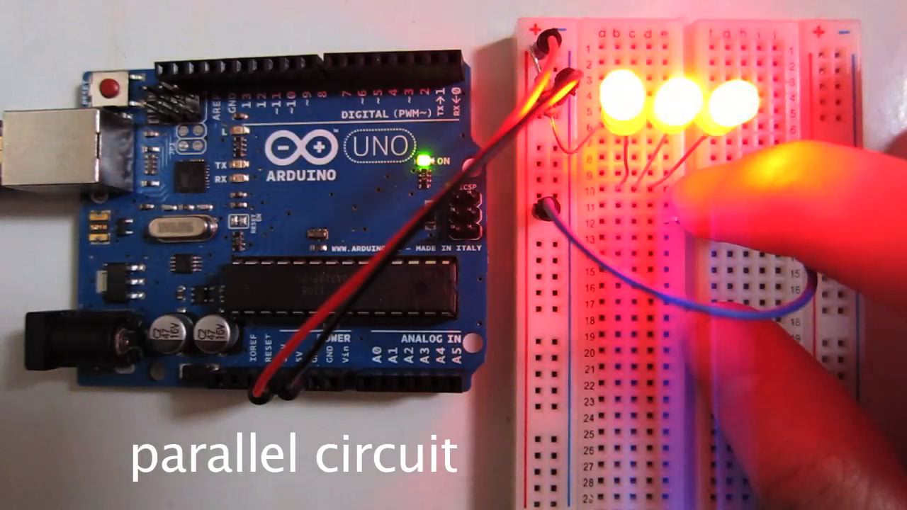
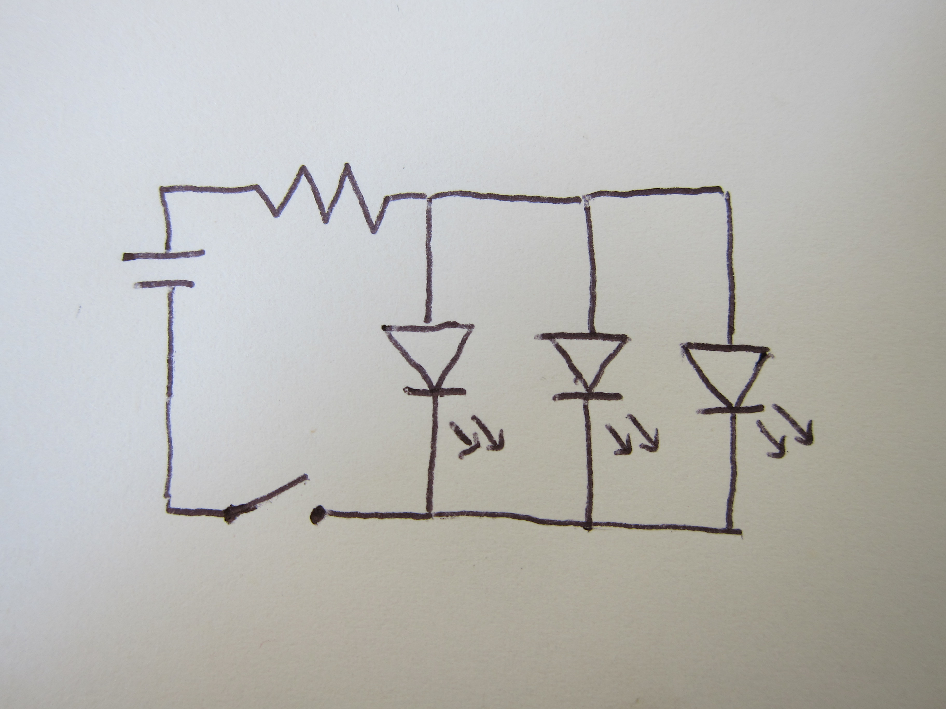
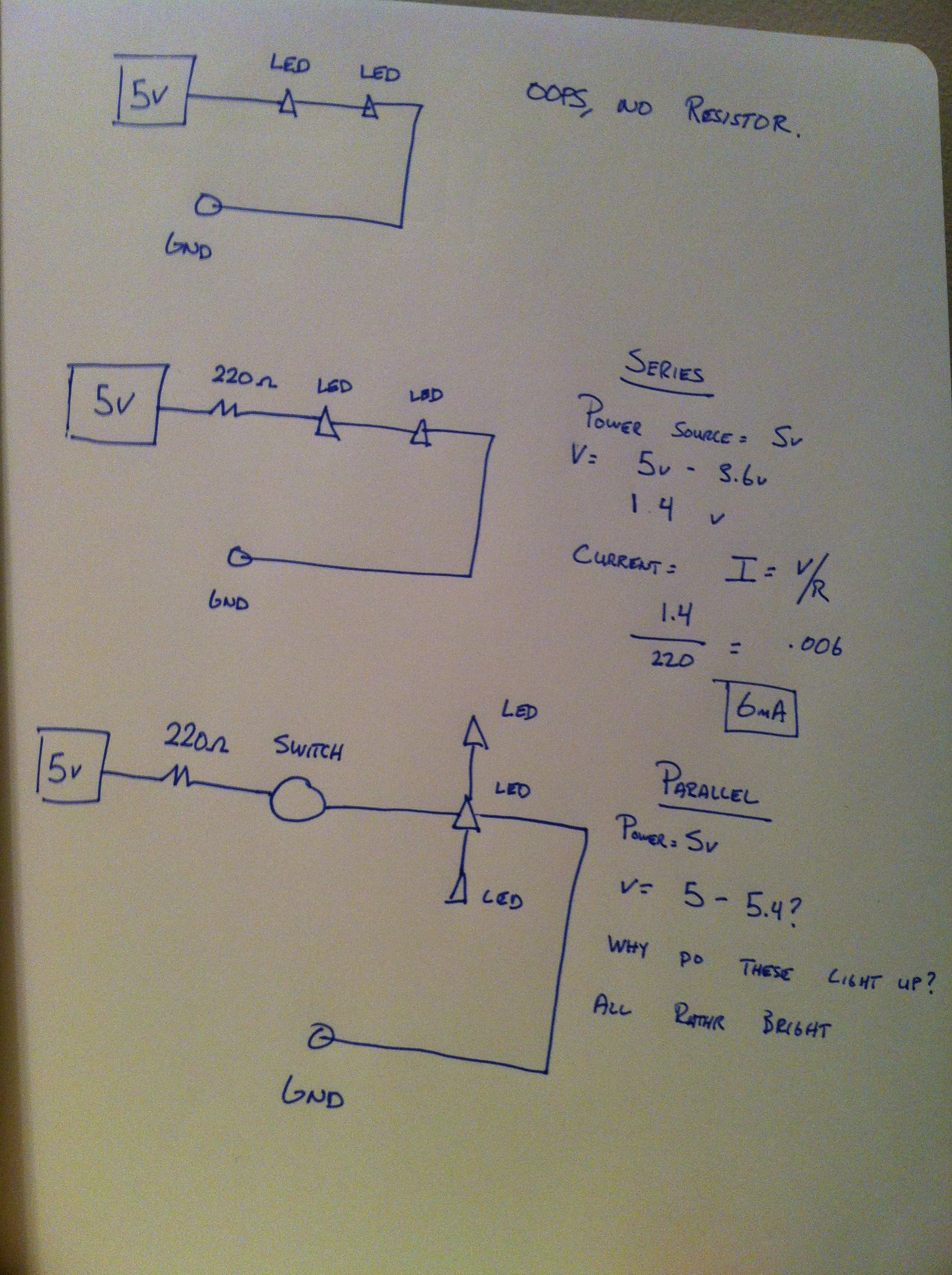
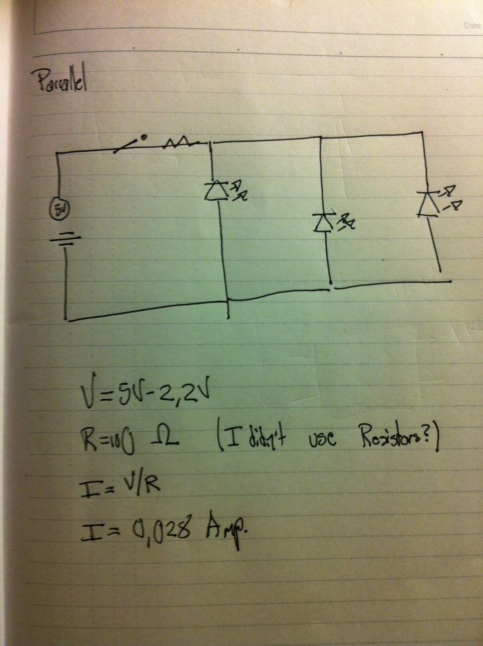
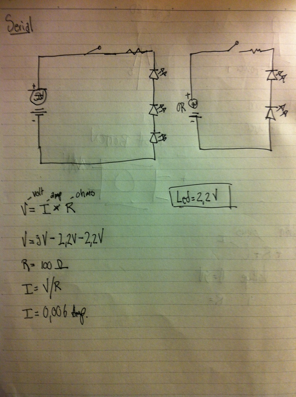
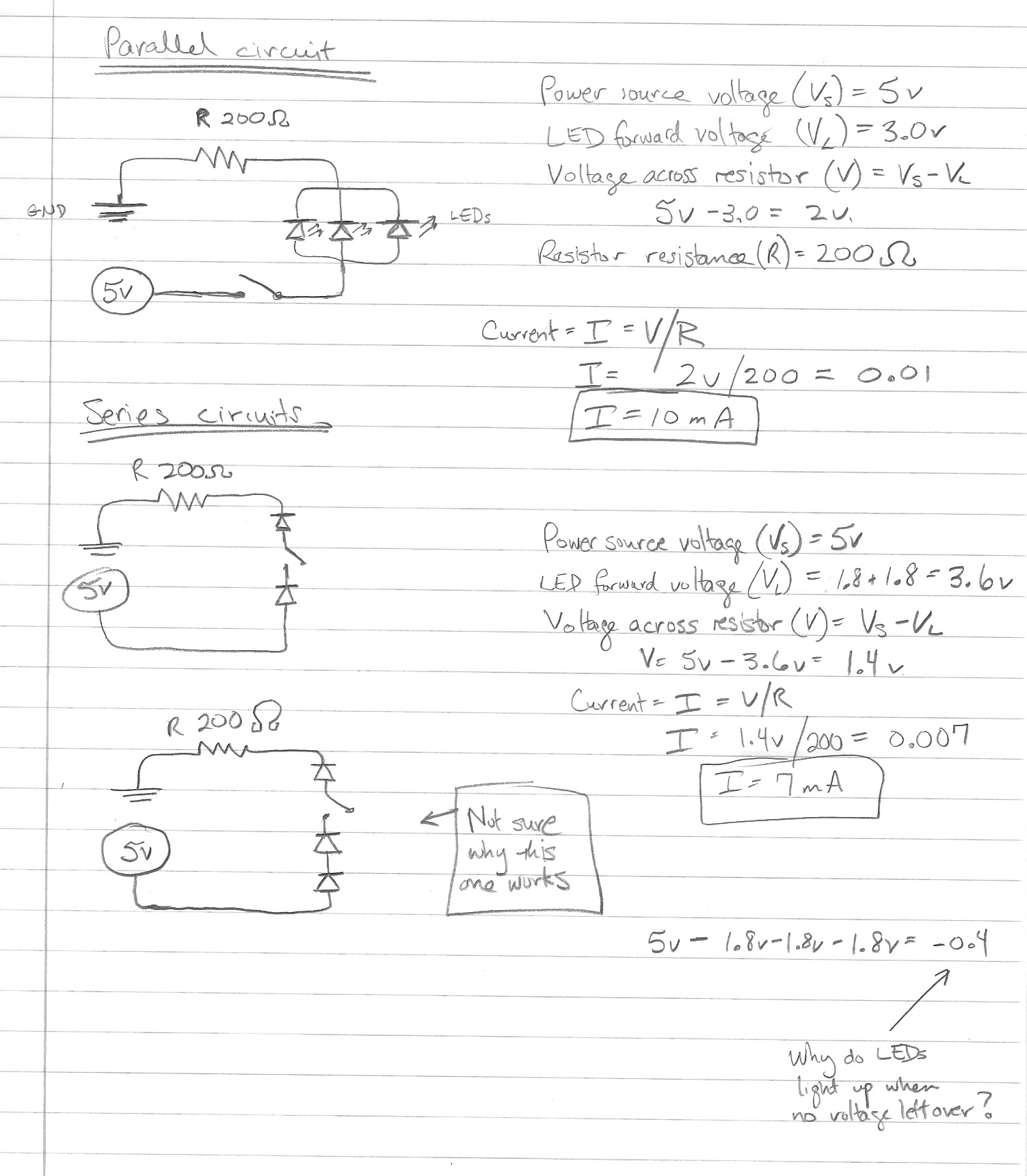
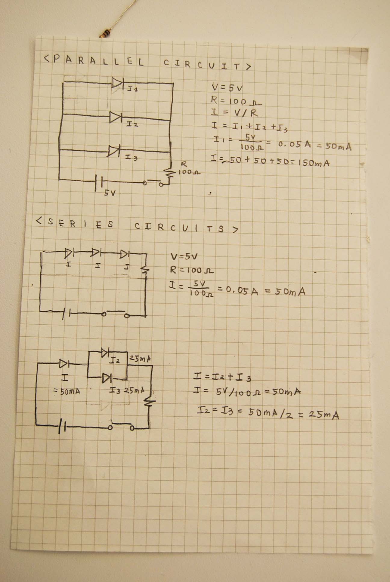
V = 5
R = 100
I = 5/100
= 0.05
Video: Circuits


