Design a lamp using the techniques, tools, and materials we have been learning over the course. Lamp and presentation are due OCT. 10. You will have seven minutes total to present. I suggest 5 minutes for presentation and 2 for feedback. You do not need to have a slide deck unless you want to. You should plan to demo. Instructable due Friday, Oct. 17.
Constraints:
1) MUST use a switch or sensor. RE: You must have a way of controlling the circuit.
2) Must have at least two states (e.g. on/off, fading fast/slow, red/blue, etc) or more.
3) You do not have to use Arduino.
4) You cannot use jumper wires *unless* it is to connect your circuit traces to the Arduino. In this case, you should consider how to integrate your Arduino into the design. Depending on your time and financial constraints, you may want to explore other types of Arduinos that better fit your design, such as a Lilypad, Flora, Gemma, Arduino Mini, etc.
5) The midterm is an individual project.
NOTE: Please do not use a breadboard for the same reasons as the Arduino constraint above. Again, the goal of this project is to evaluate your comprehension of the materials, techniques, and processes. Only using wires and a breadboard or Arduino will not help me understand that you have mastered what we have been doing in the semester.
I will be evaluating you along the following categories:
Process
– Paper prototyping interaction and structure
– Grasp of assembly and how to integrate electronics with materials
– Material is appropriate for the project
Concept + Design
– Clear design goal
– Desired interaction accomplished (What should the user be doing or feeling? What action do you want them to perform?)
– Intuitive interface (or convoluted depending on the design goal)
– Articulated audience – who is this for?
Documentation
– Create an Instructable documenting your project. Due October 17.
DUE SEPTEMBER 26
Just bring any sketches and an idea to talk through.
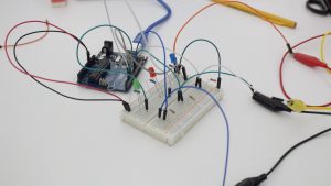
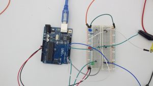
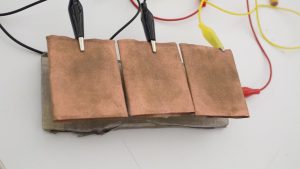
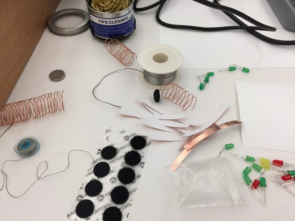
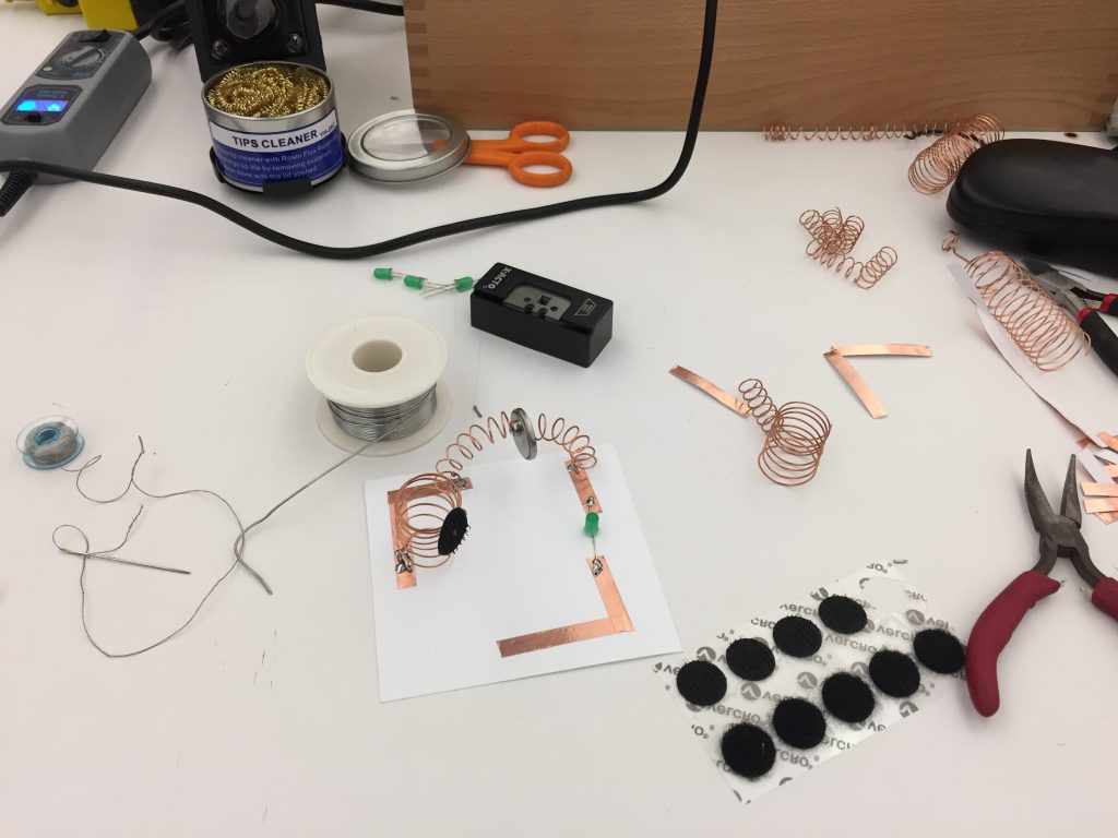
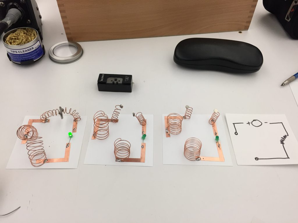
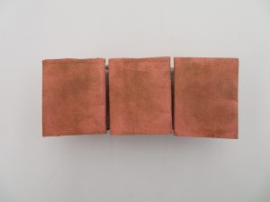
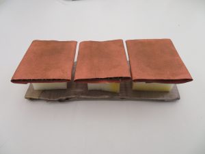
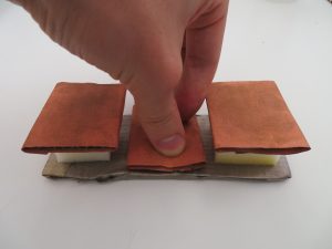
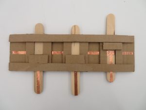
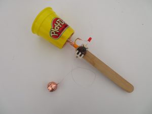
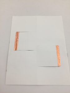
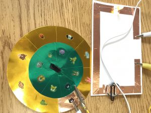
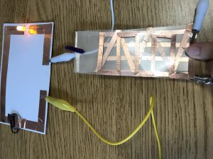
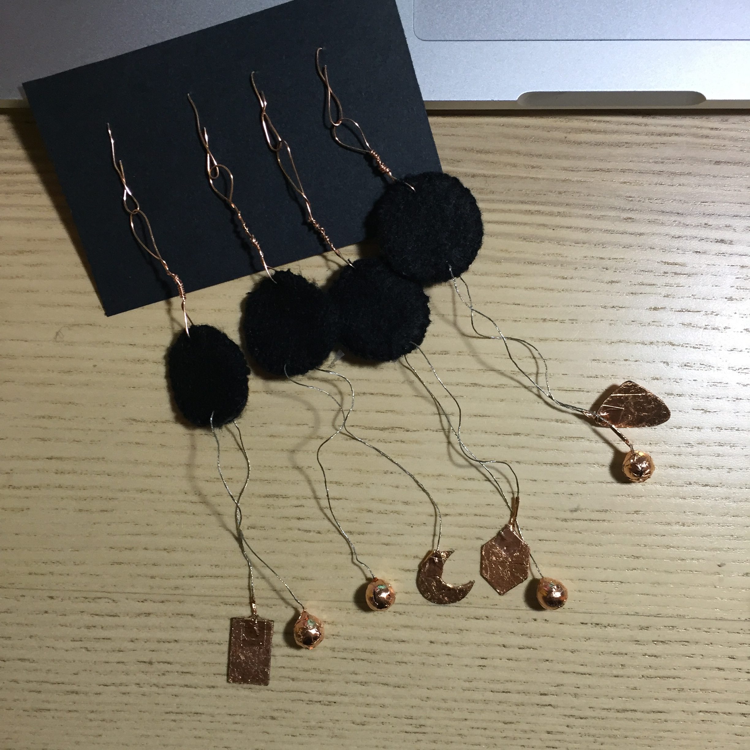
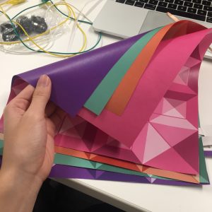
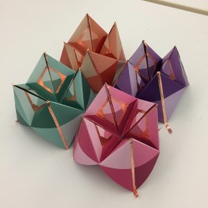
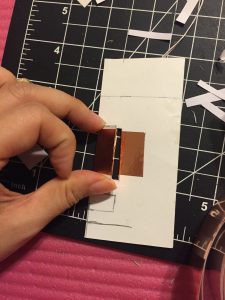 Fig.1
Fig.1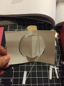
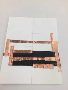
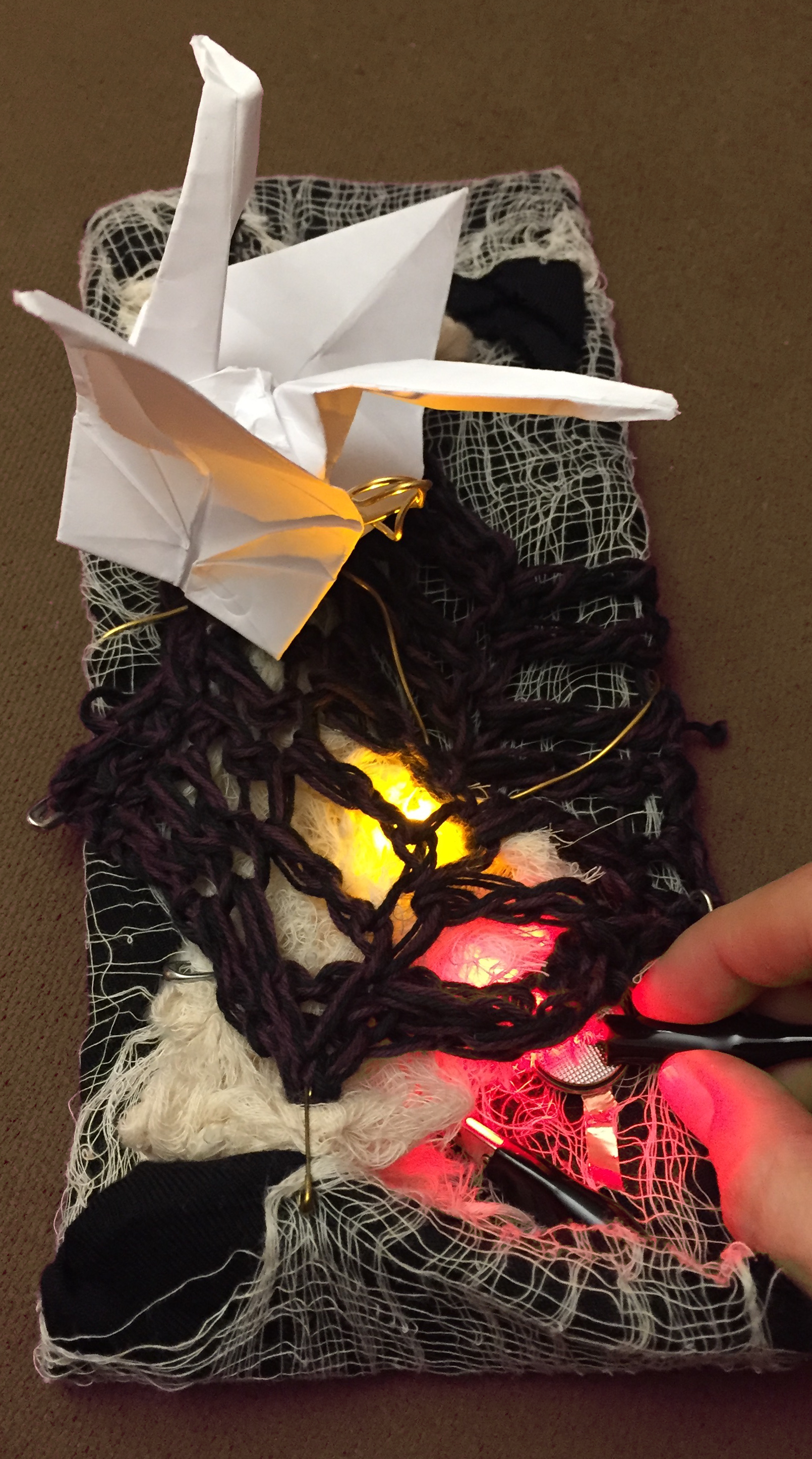
 F
F
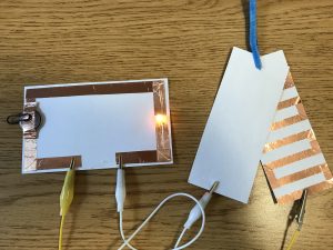
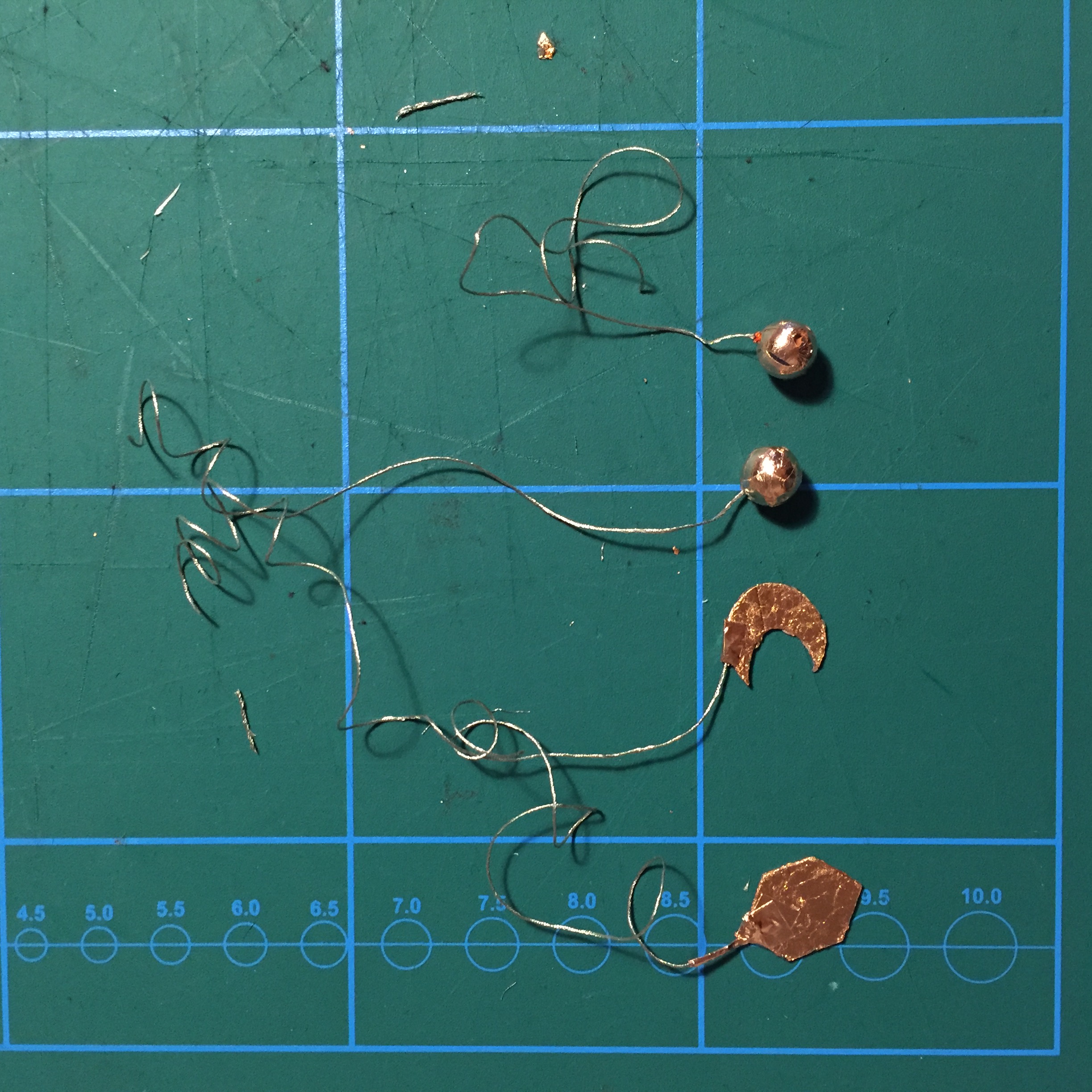
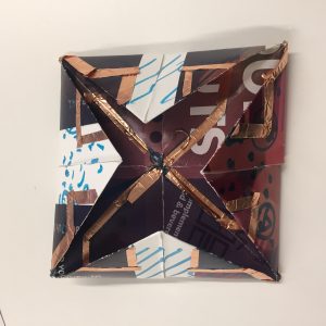
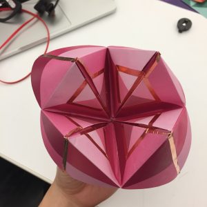
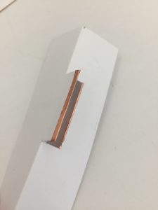 Fig.5,6
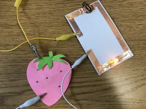
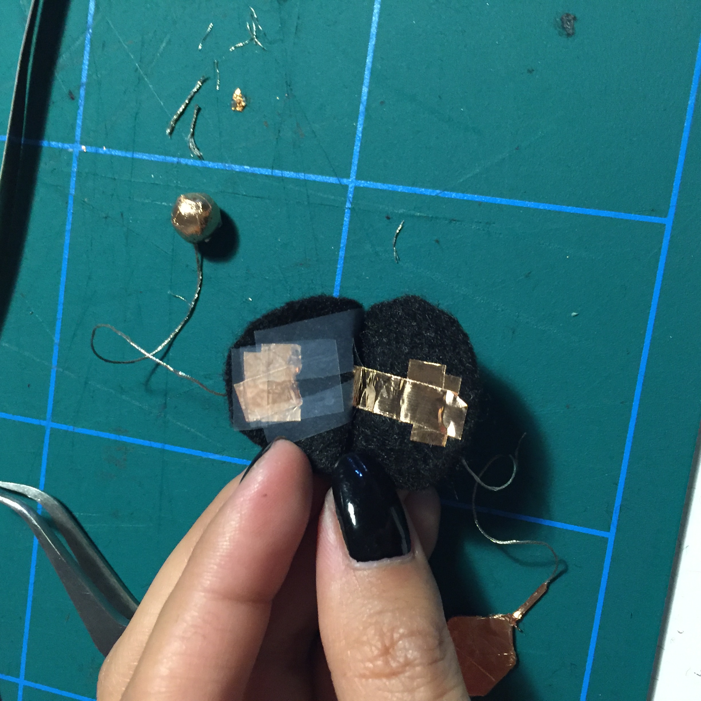
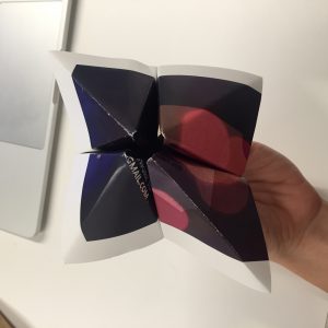
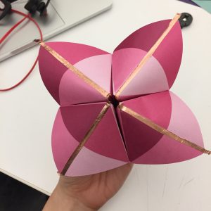
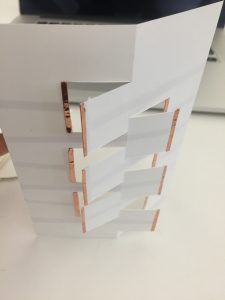 Fig.7,8
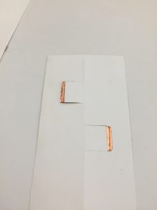 Fig.9
Fig.9