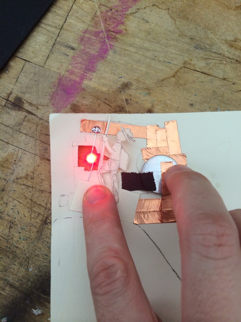
I have struggled to use a paper hand drawn image with graphite to complete a circuit. I have the notion that the darkest and most covered surface area would create the brightest LED, by having the least resistance. I also wanted to test weather I could use a more complicated image, like a tree to light up the LED at a greater distance from the banana clip to the LED pin.
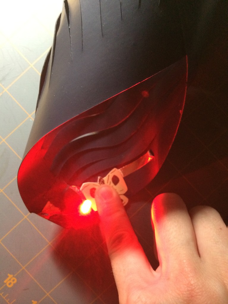
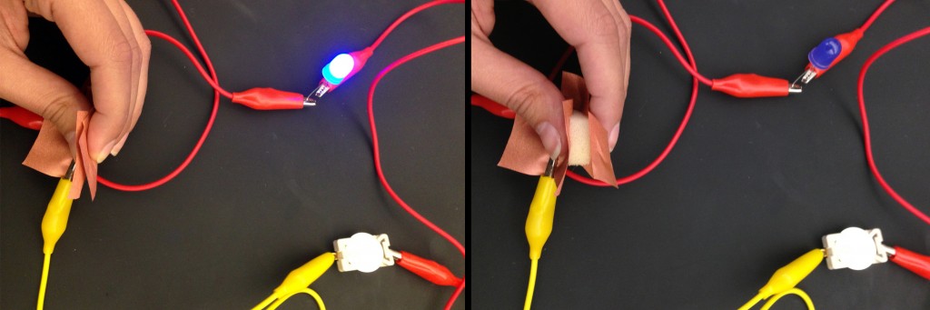
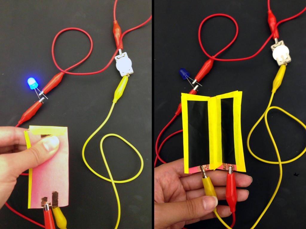
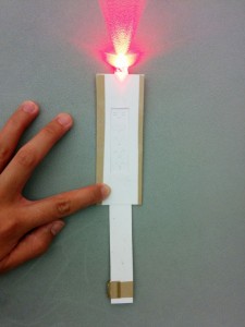
To test this I created three hand drawn shapes. A rectangle, a heart, and a tree. I tested with one banana clip connected to a 3 volt coin cell battery on the positive side to the positive LED leg and one clip connected to the negative side of the battery. The drawing on white paper with a pure graphite pencil then acted as a resistance sensor and completed the negative side of the circuit. I found that my hypothesis was partially correct and the rectangle and the heart both created bright LEDs. This means that both of them had less resistance than the tree image. The tree only gave the faintest light to the LED, and that light got dimmer as I moved up the branches and further from the negative clip. This tells me that the graphite has some resistance and the thinner the lines of graphite, the more energy is dropping off of the circuit.
I also tried it in various configurations, the only one that worked was having the positive side of the LED connected directly to the battery with a clip and having the negative side passing through the graphite and paper.
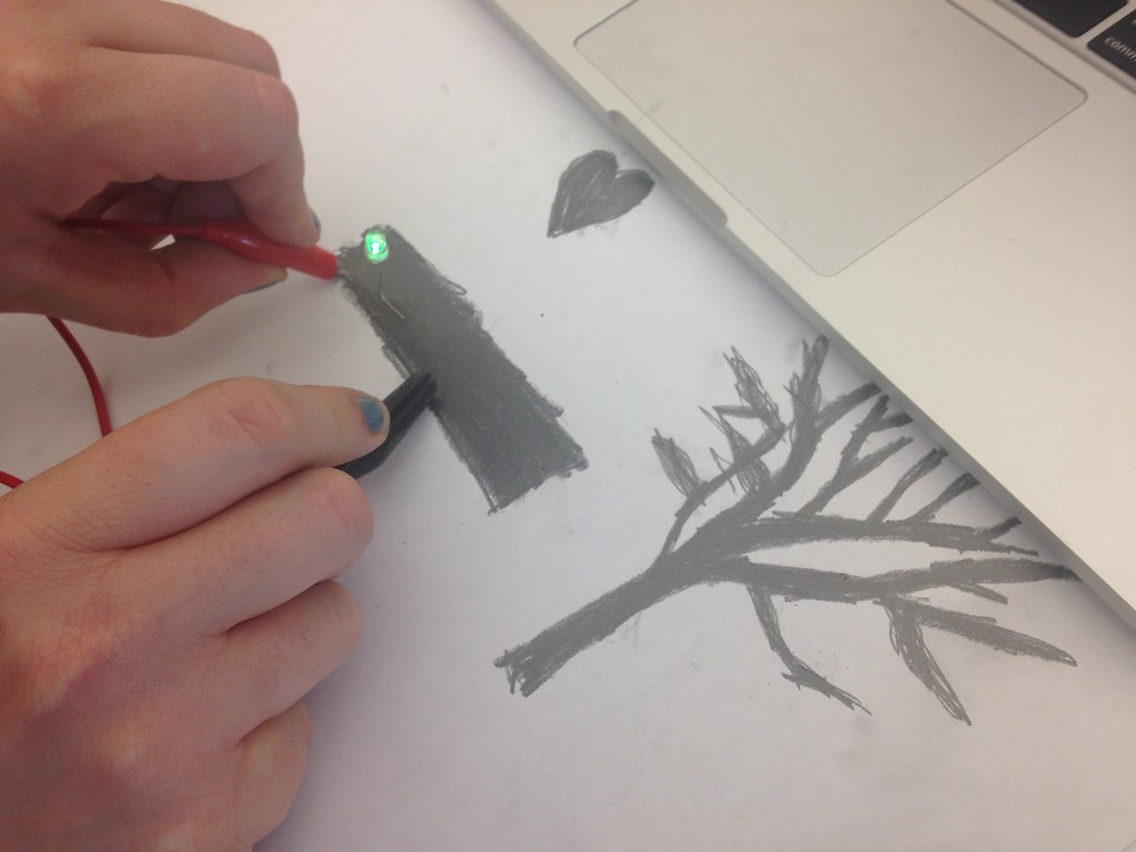
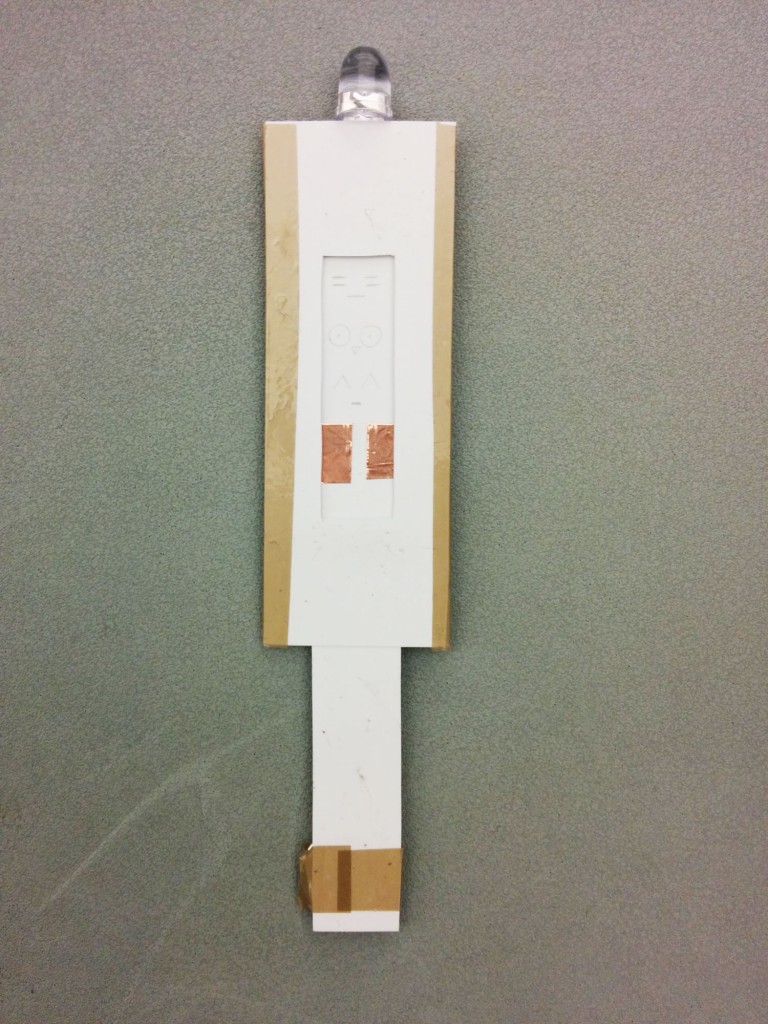
The Rectangle: Very bright LED
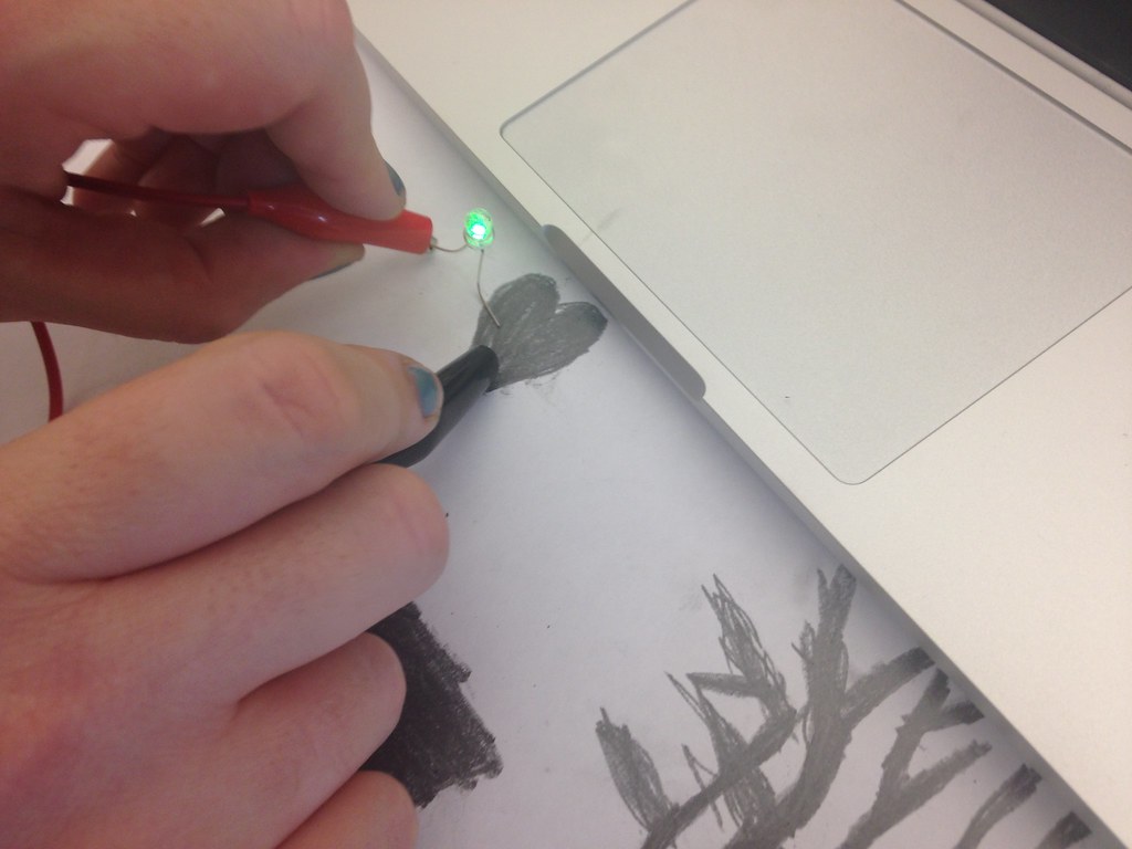
The Heart: Very bright LED
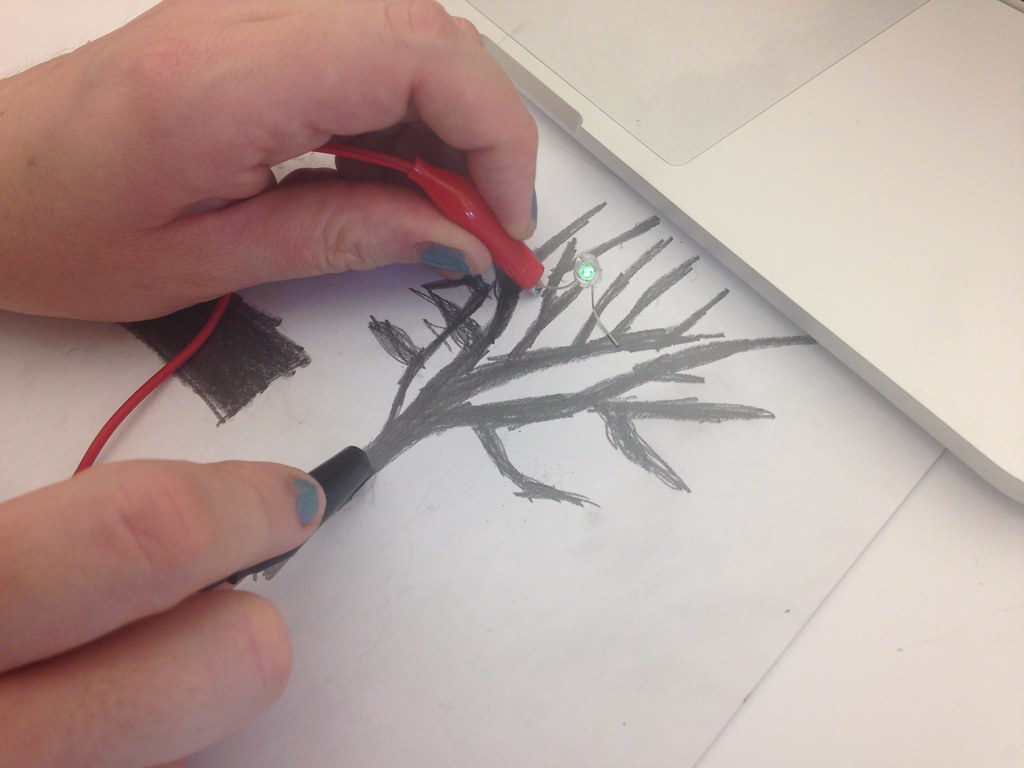
The Tree: The LED got dimmer as I moved up the branches.