Sunglasses Lamp (WEEK7)

It is a glasses lamp. When the sensor touches the wearer’s face the LED turns on.

Materials: 1megaohm resistor, ATtiny, Battery, LED, Conductive tape

I applied the basic capacitive sensor circuit on a sunglasses by connecting the sensor pin to the top of the glasses where touches the wearer’s eye bone.

Pillow Lamp

It’s a pillow lamp.

In my original idea, this lamp could light up automatically when environment getting dark. When users laying heads on it, the light turns off.

But there is some problem with ATTiny. Finally the lamp can be turned off when laying heads on it. But it can’t light up automatically when environment getting dark.

IMG_7038_2 IMG_7037_2IMG_7038_2 IMG_7040_2 IMG_7045_2 IMG_7055

Circuit Prototype

IMG_7033 IMG_7035 IMG_7087 IMG_7091 IMG_7092 IMG_7097


Behavior Story (Week 6)

Soothing/Comforting/Purring Pet (Or rather: The Angry Firefly)

IMG_0013

Don’t wake up the angry firefly…

The plan for my Behavior Story took a detour when I underestimated how loud/strong the vibration from the mini vibe motor could be. I had initially planned on making a nice, soothing toy/object that created a gentle vibration and pulsing light when you put your hand on it. Instead what I got was an angry cricket/firefly that was irritated when you bothered it.

A photoresistor at the top of the jar detects when the user places his or her hand above it, causing the angry firefly inside to wake up (lighting an LED and powering a mini vibe motor in short pulses) until the user’s hand is removed.

Materials:

  • 1x Adafruit Trinket Pro 5V (or any other microcontroller that fits in the container of your choice – in this case I was using a glass jar with a plastic lid and needed something compact)
  • 1x Photocell/Photoresistor/LDR
  • 1x 5mm LED (bright white)
  • 1×1300 mAh LiPo Battery* (+battery “backpack” to connect it to microcontroller) *used 9v battery instead – bulkier, but still works
  • 1x 100 ohm resistor (for LED)
  • 1x 100k ohm resistor (for LDR/photocell)
  • Hookup wire/conductive thread + solder + soldering iron etc.

for the vibe motor circuit:

  • 1x NPN Transistor
  • 1x 1k ohm resistor
  • 1x 1N4001 Diode
  • 1x capacitor
  • 1x 33 ohm resistor
  • 1x mini vibe motor


The project is my first attempt at using a Trinket microcontroller with soldered connections – something I tried in order to keep the components as compact as possible. However, the project still required a 9v battery to work effectively (the vibe motor requires a decent amount of power), making it bulkier than intended.

IMG_9686 IMG_9689  IMG_9692IMG_0014IMG_0015IMG_0016IMG_0018IMG_0019IMG_9690IMG_9691


Fritzing Diagram / Breadboard Circuit:

Vibe-LED-LDR_bb


for Arduino code, see below:
Continue reading

Behavior Project (Week 7)

“Kick!”

I chose to embody the word “kick” and felted a little adidas soccer shoe. I then attached it to a servo and coded the servo to rapidly move forward about 45 degrees, like a kick, and then slowly move back to its initial position. I then attached a button that I made out of felt to the circuit and coded it to “kick” the foot when pressed.

Check out the video below!


felted soccer shoe

felted soccer shoe

Pieces of the button

Pieces of the button

Finished Button

Finished Button

Stand for the foot

Stand for the foot

Completed foot

Completed foot

Behavior Story_Wave

Behavior Story_Wave

On his first day of  fifth grade, Bob, decided that he was finally going to say hello to his kindergarten crush, Beca. The only problem was that Bob was so shy he could never muster the courage to actually speak to Beca. So, Bob did what Bob does best, and built a waving robot to do the talking for him.

Unfortunately, when he used it at school Tess, the girl sitting in front of Beca, thought the wave was meant for her. Tess walked over and  started talking to Bob….and never stopped. The two lived awkwardly ever after.

  •  Mini Servo Motor
  •  Potentiometer
  •  Copper tape
  •  Wires
  •  Arduino

Wave


Week 7 Emotion


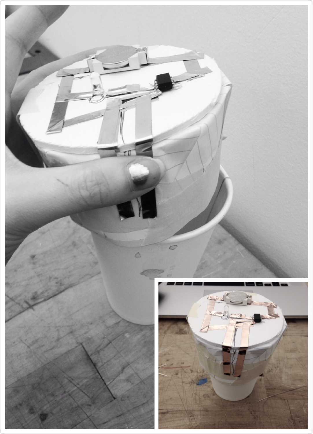
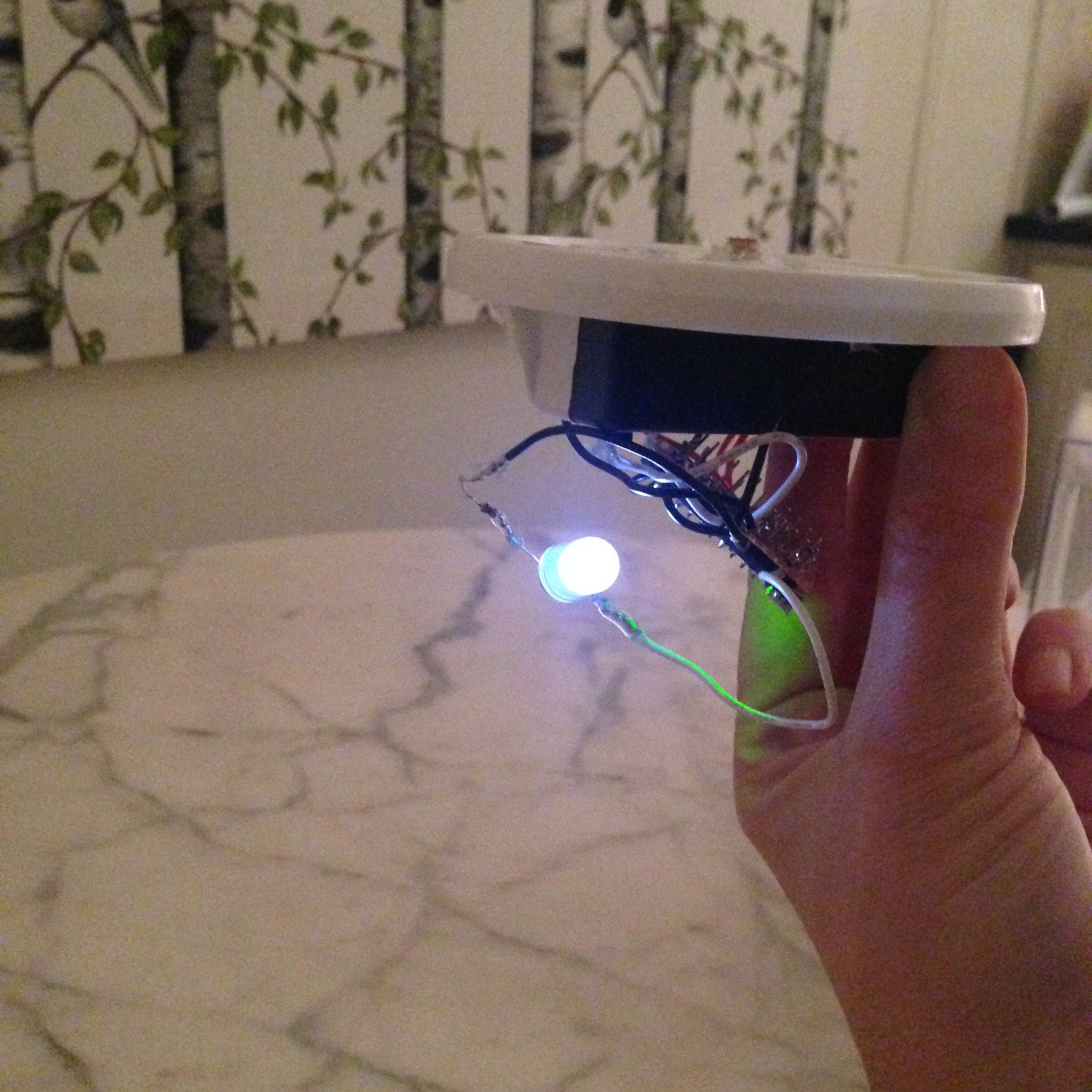
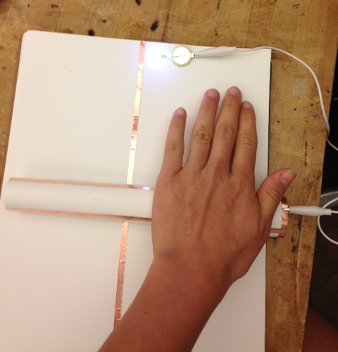
The heart beats fast when the flower bunch gets close to it.

IMG_0878IMG_0879IMG_0880IMG_0883


Code

// —————————————————————————

// Example NewPing library sketch that does a ping about 20 times per second.
// —————————————————————————
#define ledPin 13
#include <NewPing.h>

#define TRIGGER_PIN 12 // Arduino pin tied to trigger pin on the ultrasonic sensor.
#define ECHO_PIN 11 // Arduino pin tied to echo pin on the ultrasonic sensor.
#define MAX_DISTANCE 200 // Maximum distance we want to ping for (in centimeters). Maximum sensor distance is rated at 400-500cm.

NewPing sonar(TRIGGER_PIN, ECHO_PIN, MAX_DISTANCE); // NewPing setup of pins and maximum distance.

void setup() {
pinMode (ledPin, OUTPUT);
Serial.begin(115200); // Open serial monitor at 115200 baud to see ping results.
}

void loop() {
delay(3); // Wait 50ms between pings (about 20 pings/sec). 29ms should be the shortest delay between pings.
unsigned int uS = sonar.ping(); // Send ping, get ping time in microseconds (uS).
Serial.print(“Ping: “);
Serial.print(uS / US_ROUNDTRIP_CM); // Convert ping time to distance in cm and print result (0 = outside set distance range)
Serial.println(“cm”);

if (uS / US_ROUNDTRIP_CM > 30) { // This is where the LED On/Off happens
digitalWrite(ledPin,HIGH); // When the Red condition is met, the Green LED should turn off

}
else {
digitalWrite(ledPin,LOW);

}
if (uS / US_ROUNDTRIP_CM <= 30 || uS / US_ROUNDTRIP_CM >= 0){

}
else {
Serial.print(uS / US_ROUNDTRIP_CM);
Serial.println(” cm”);
}
delay(3);
}