How can we use technology to protect women?
Roses developed thorns after being abused by predators attracted to their sweet smell. Inspired by this defense mechanism, we have created an exoskeleton that allows women to protect themselves from sexual assaults.
Precedents
We looked into existing projects that touched on the theme of self-protection through wearables.
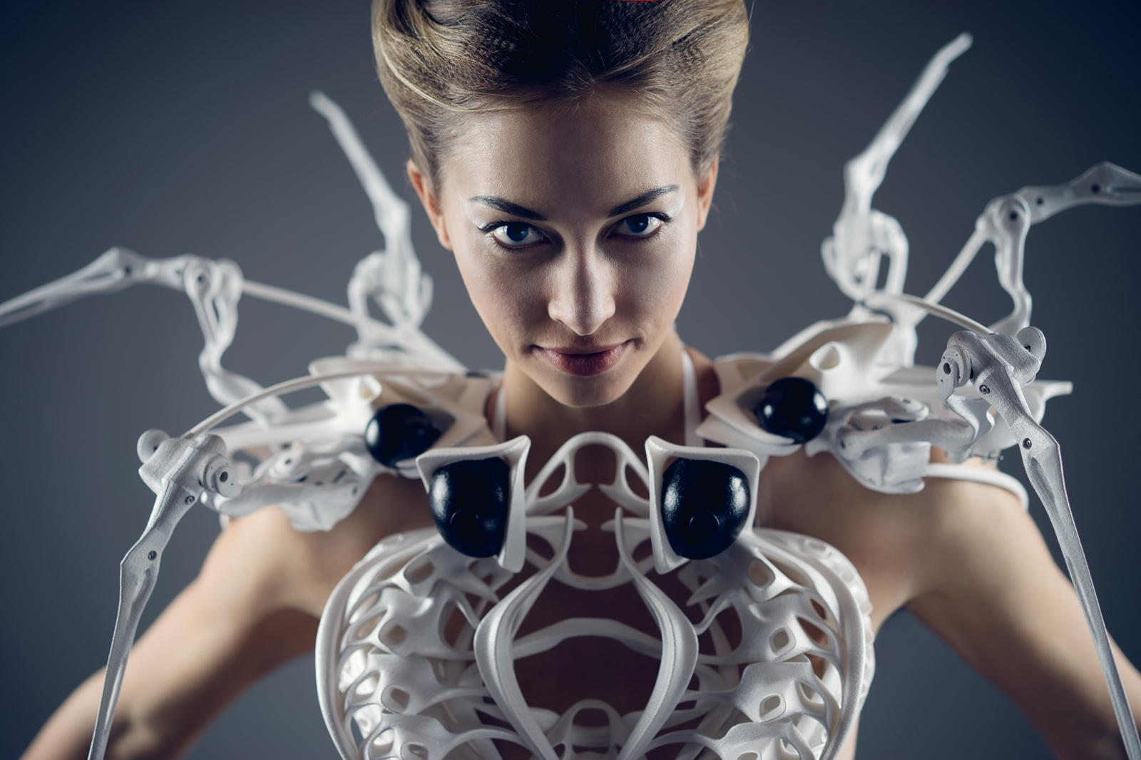
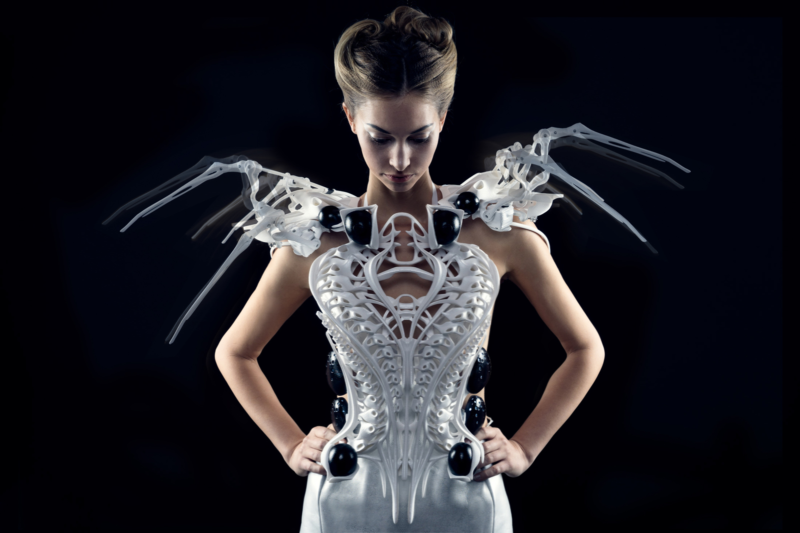
One of our biggest inspirations was the Spider Dress by Anouk Wipprecht. It plays with the idea of planting spider legs onto the shoulders of the wearable. If there are people nearby the dress, the legs of the spider would extend, sending the signal of “do not approach” to the outsiders. This dress inspired us with its biological yet mechanical movements as well as the play of integrating an animal mechanism into a wearable.
Another precedent that inspired us is Birce Ozkan’s Self Defense Wearable for Women. Inspired by hedgehogs, she wanted to create a wearable belt that imitates the movements of a hedgehog when it is prepared to defend itself.
Though we were inspired by these wearables and their incredible messages, we wanted to create something that was more discrete and feminine. We wanted our exoskeleton to be elegant and fierce looking.
Initial sketches
We were imagining the sensors to be activated through proximity or touch. So we were thinking of either adding a capacitive sensor or proximity sensor.
Prototyping
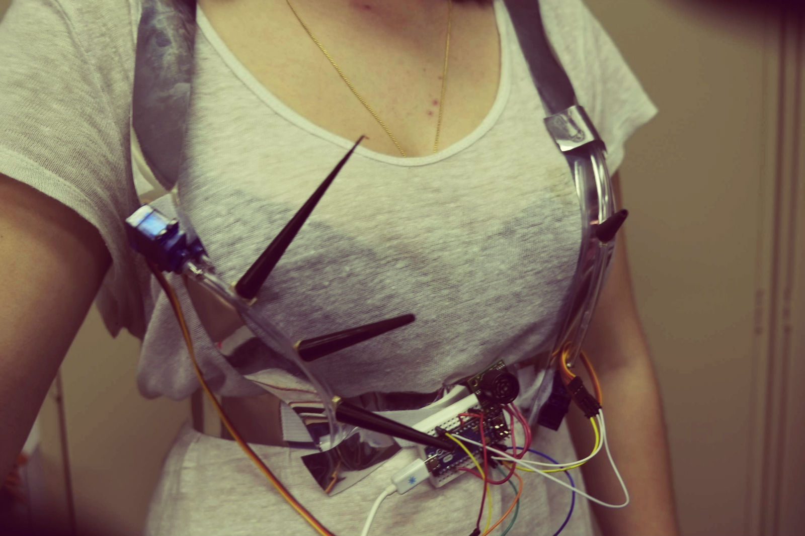
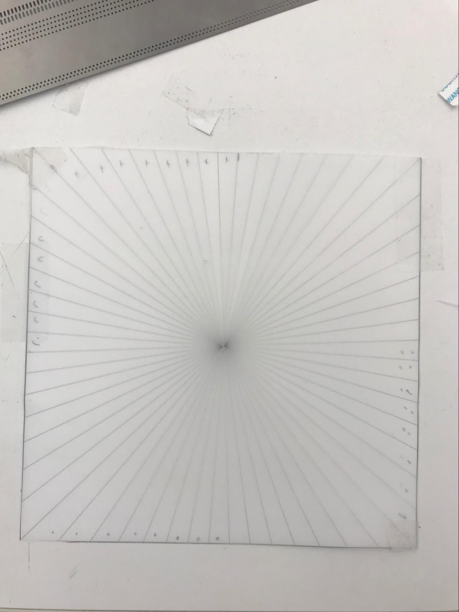
We begin the prototyping with seeing how the flip dot moves with a spike attached to it. Once we saw that its movement was what we wanted to achieve, we tried with 2 flip dots.
Then we started thinking about how the movement of the flowers on the neck would look like. We wanted the to become spikier once the flexinol wire shrinks too.
Making
The Spike
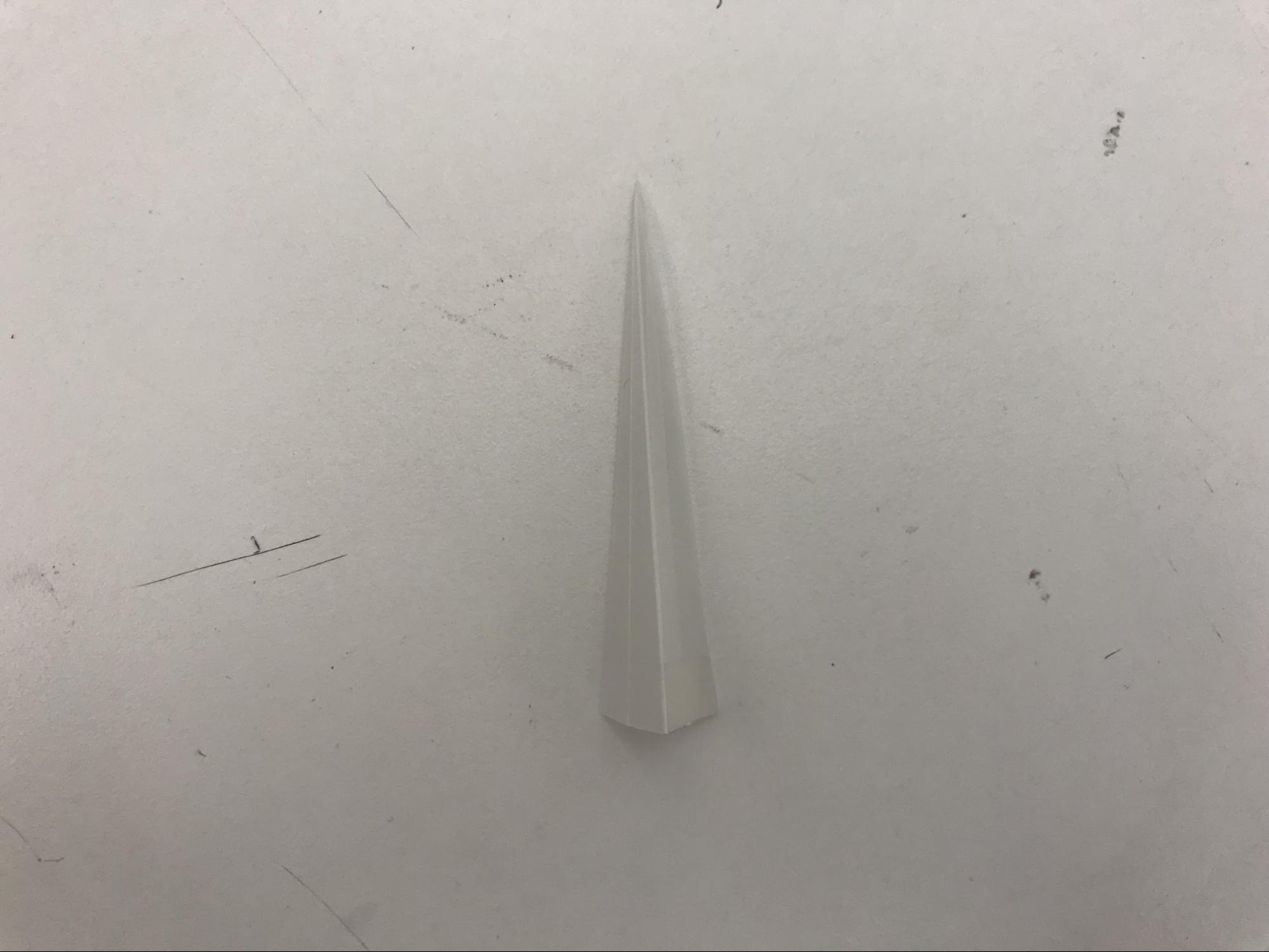
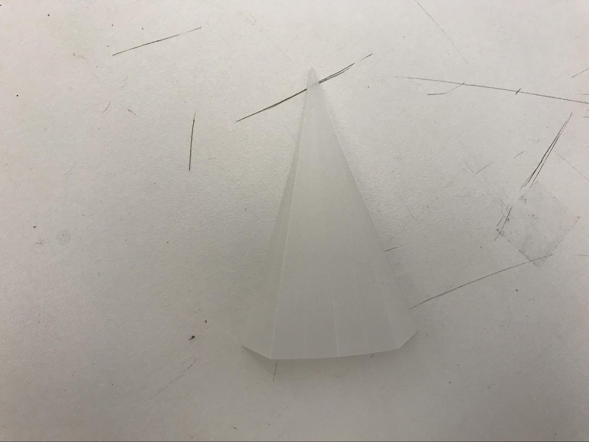
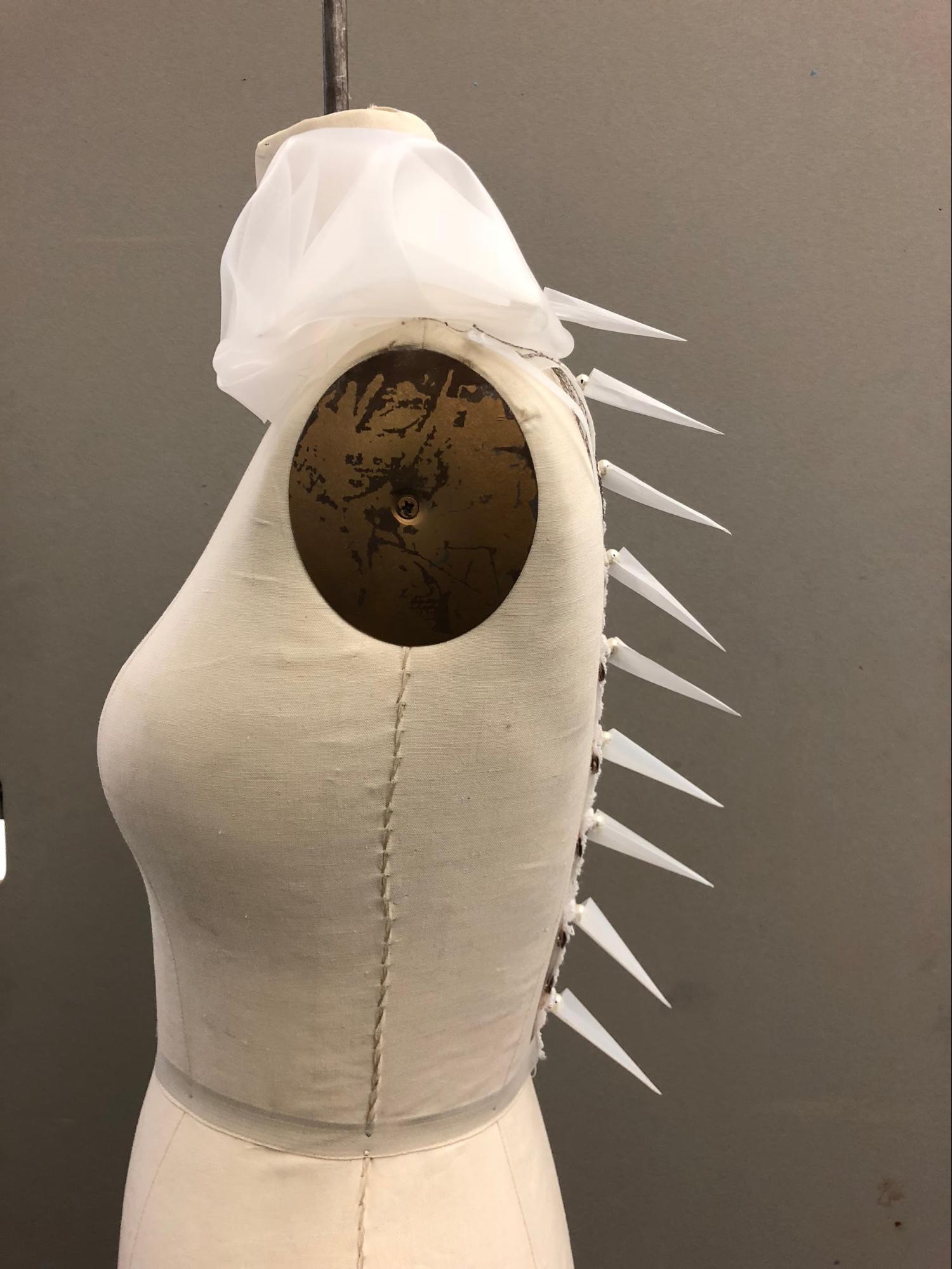
We made spikes to attach to the flip dots. However, the initial material we made the spikes from resulted to be too heavy for the flip dots, so we used rice paper for flip dots that do activate.
Diamond Shoulder
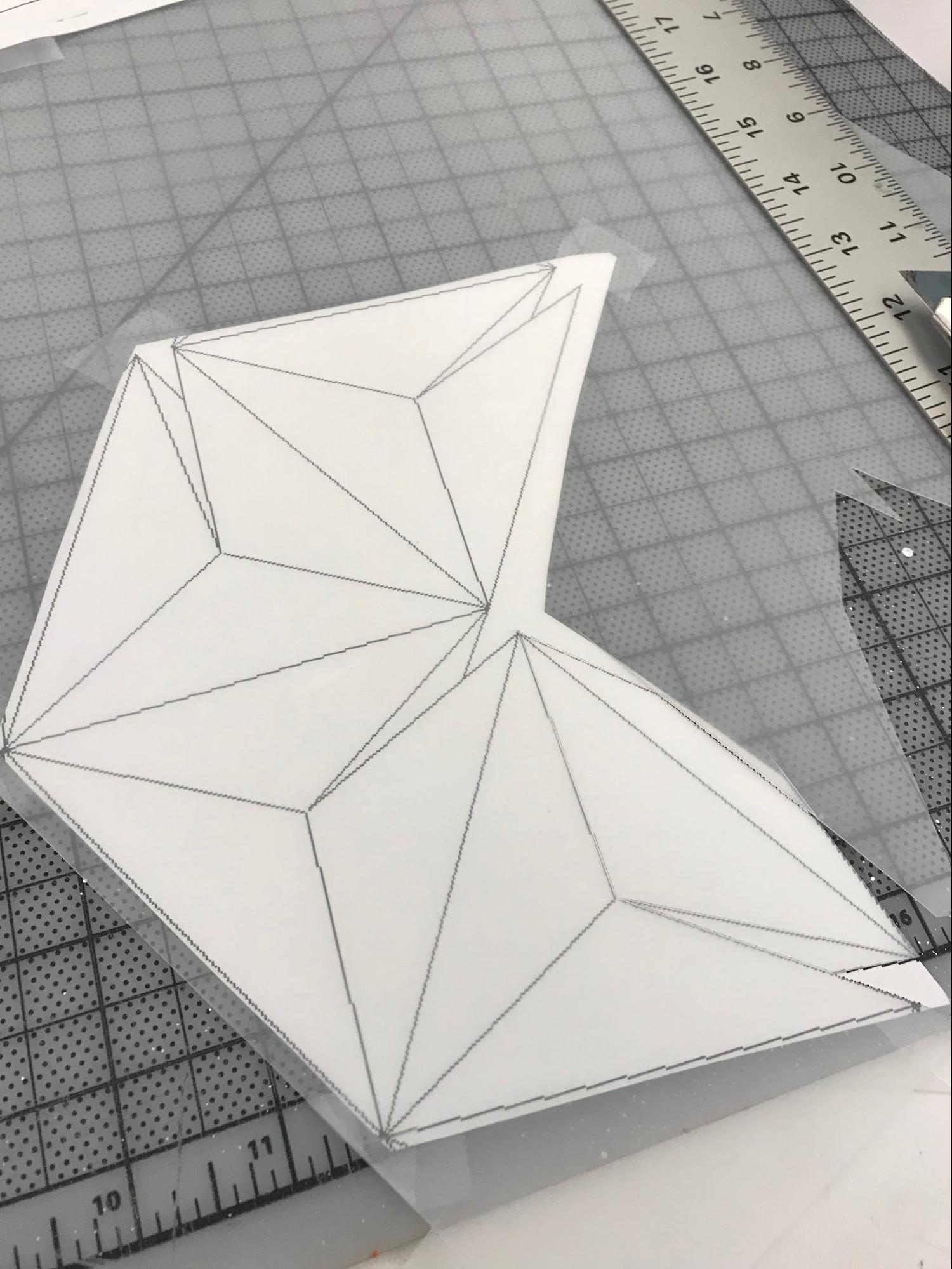
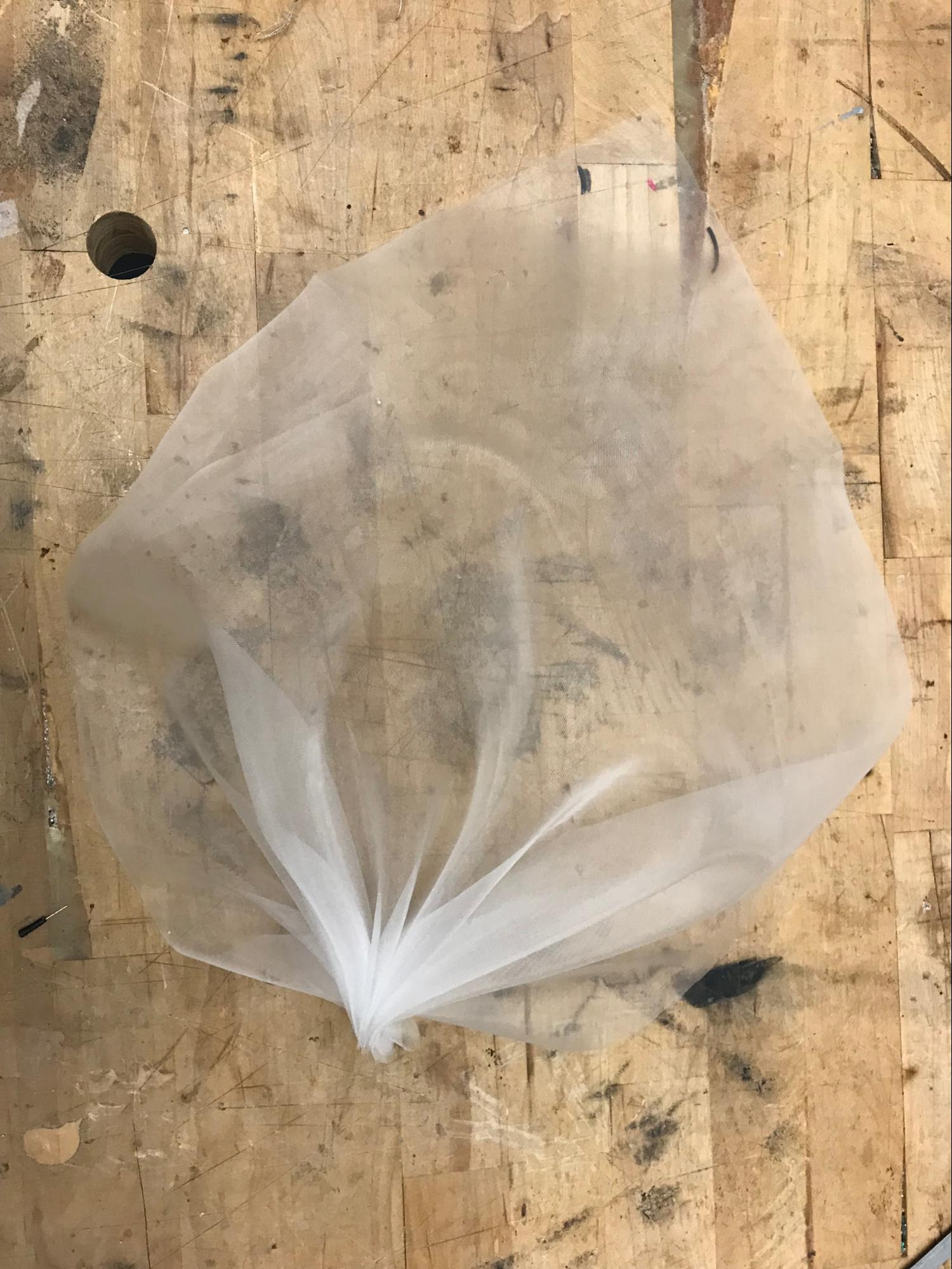
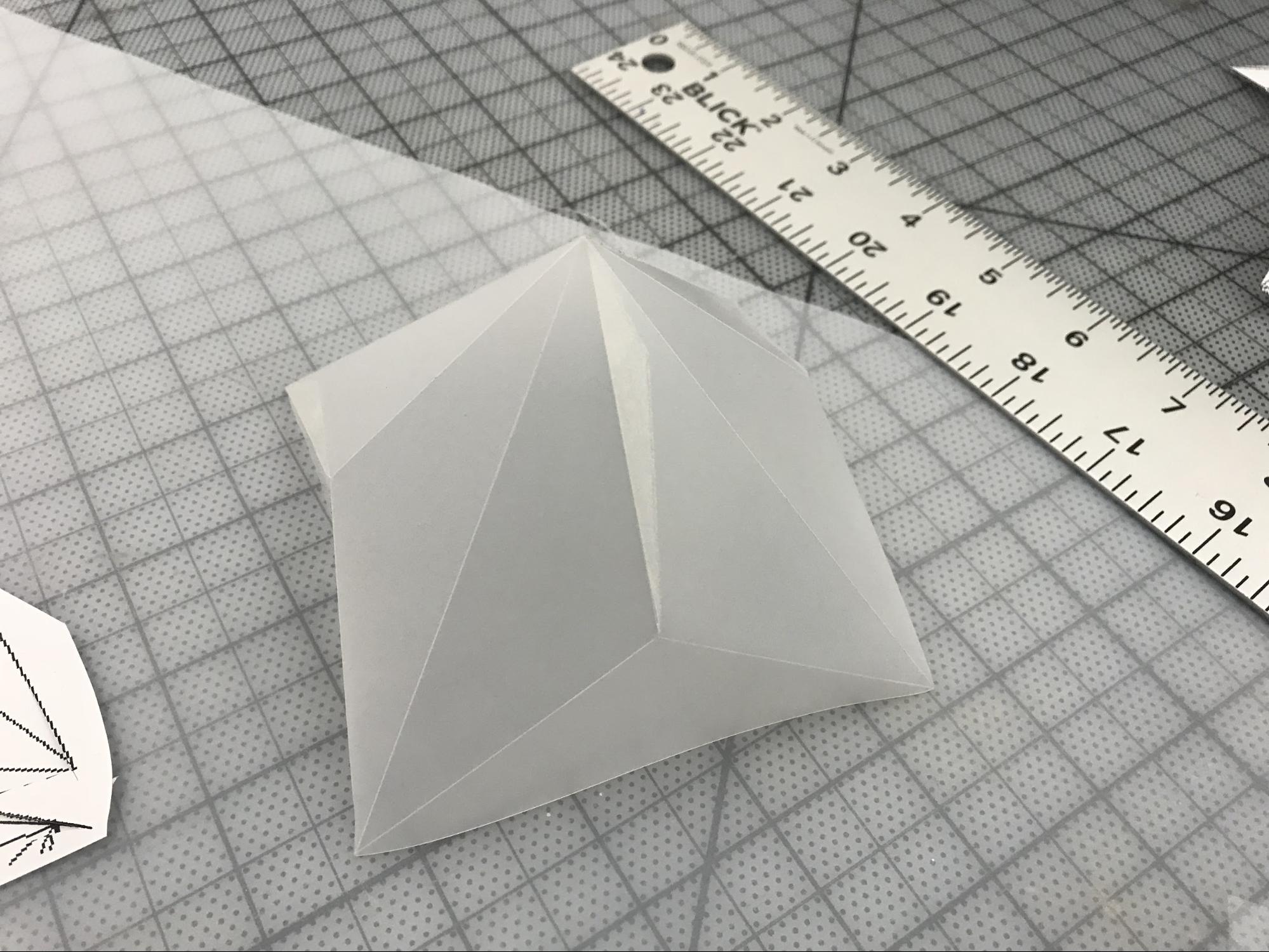
We also made 2 diamond shoulder pieces to contain the batteries and the Arduino UNO, and covered them with tulle to make the appearance softer.
Circuit
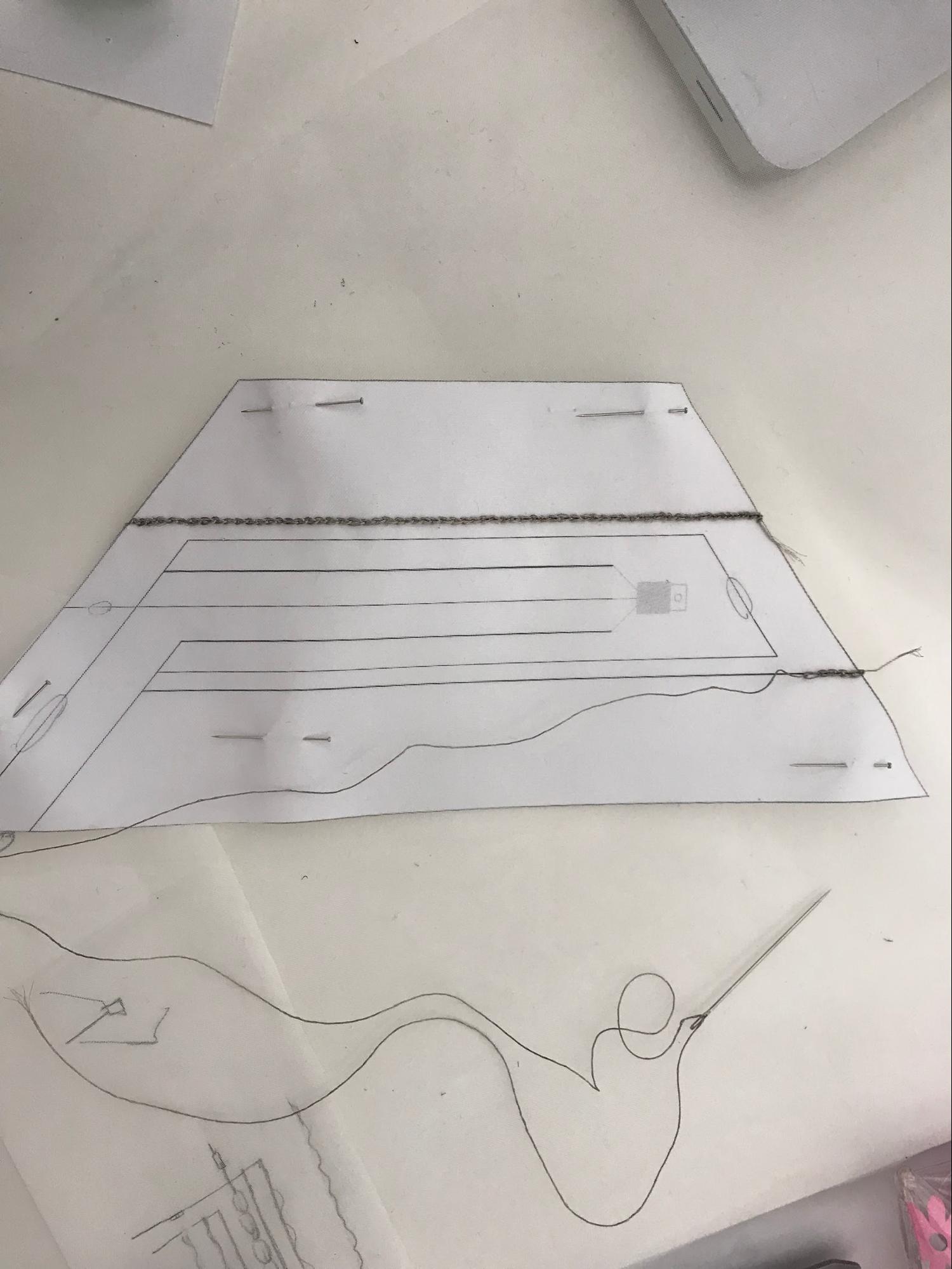
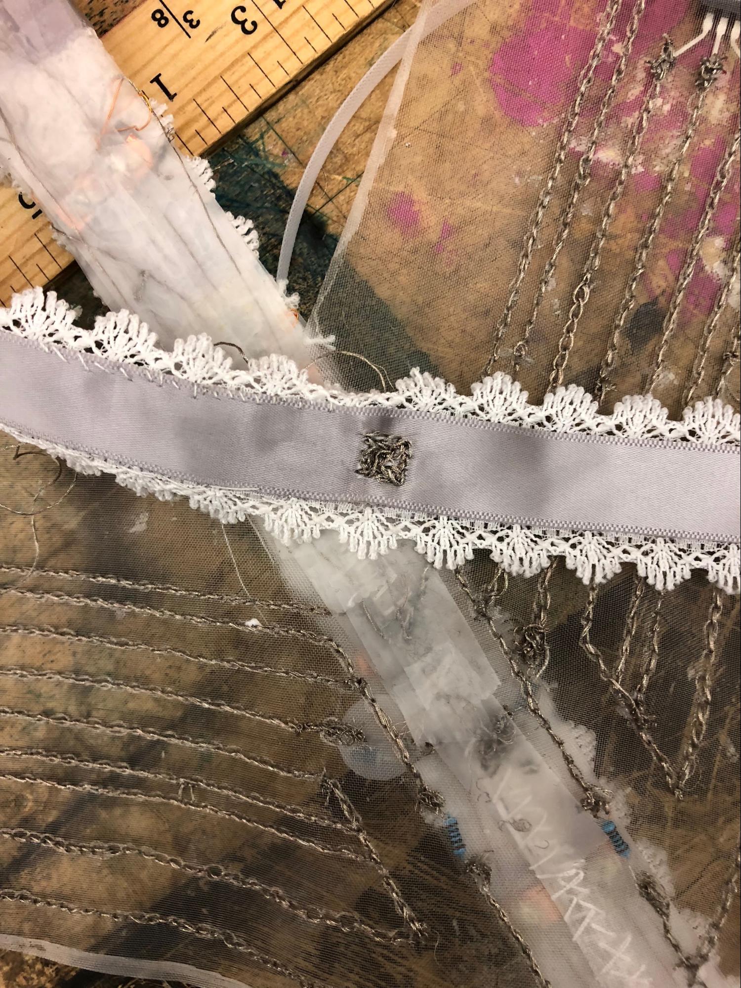
We also began to embroider the circuit into another piece of tulle in order to make it part of the back piece, as well as ease of access to connect to the batteries and Arduino on the shoulder.
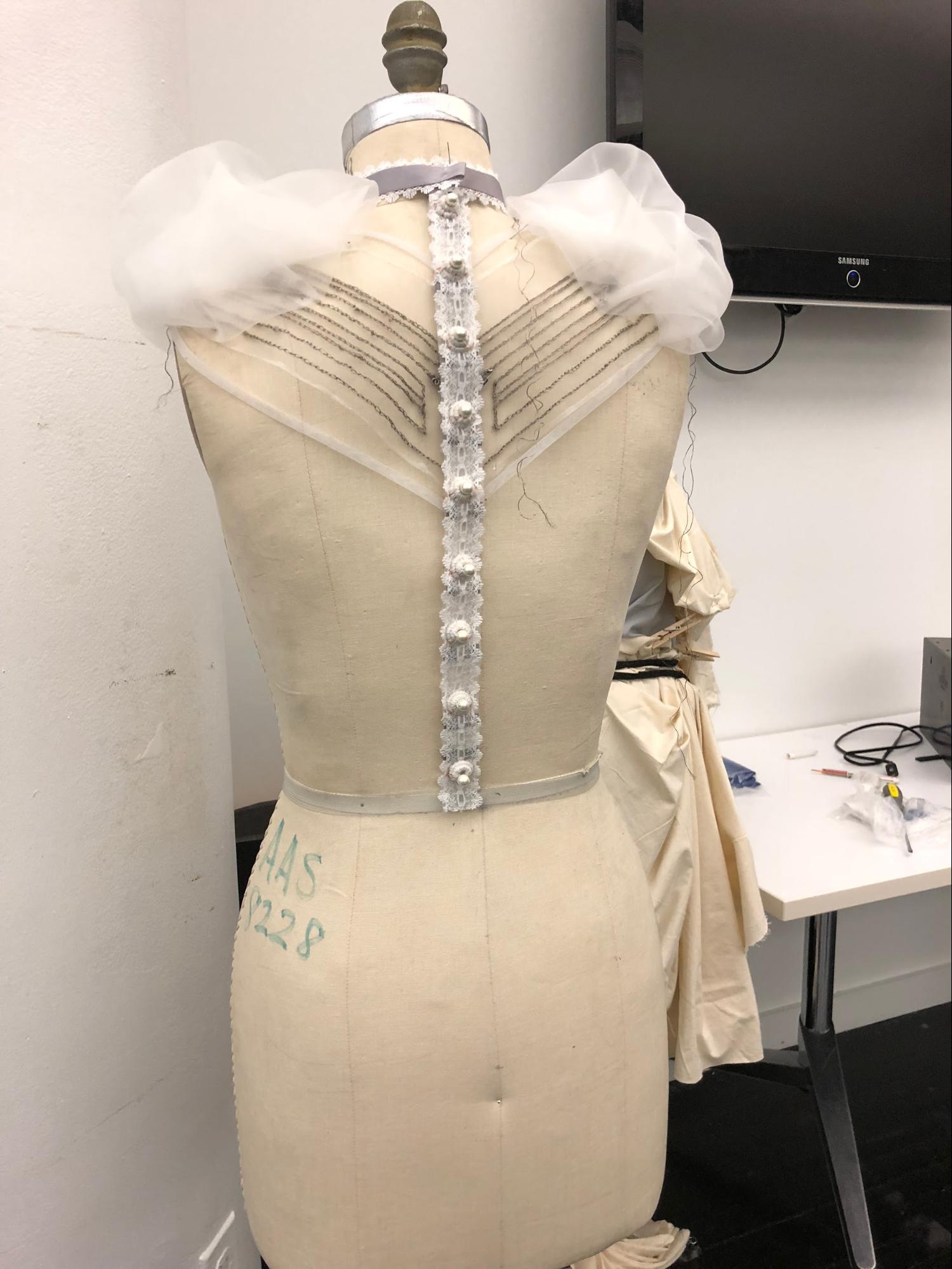
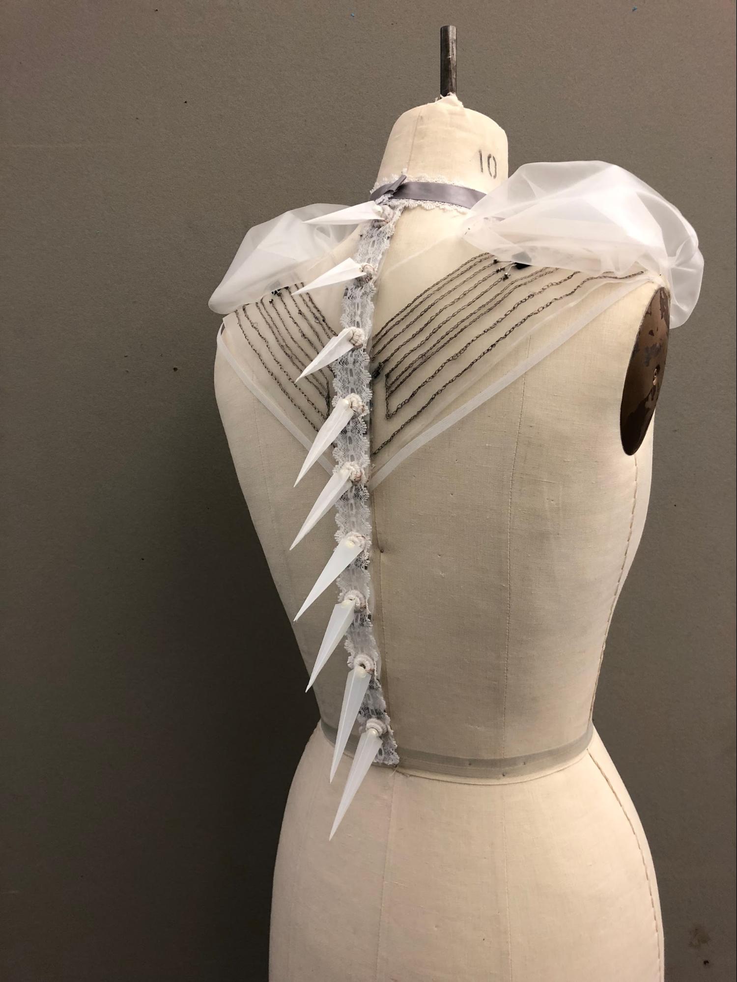
Back piece
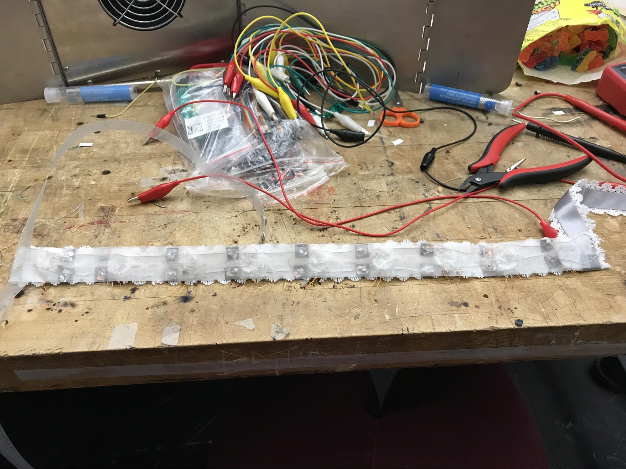
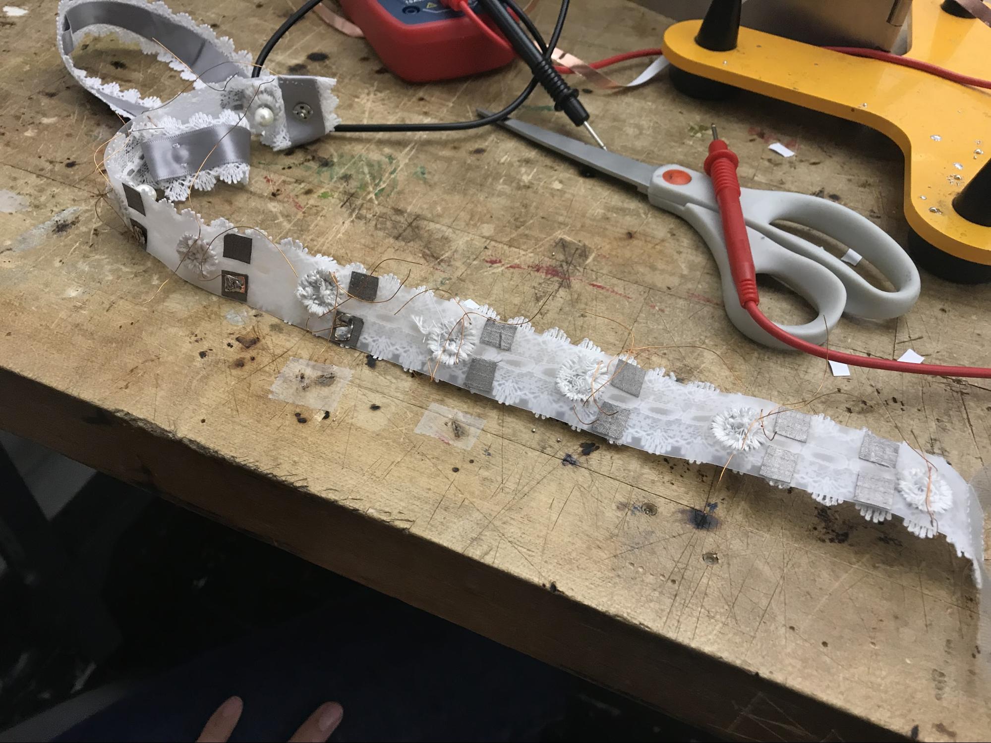
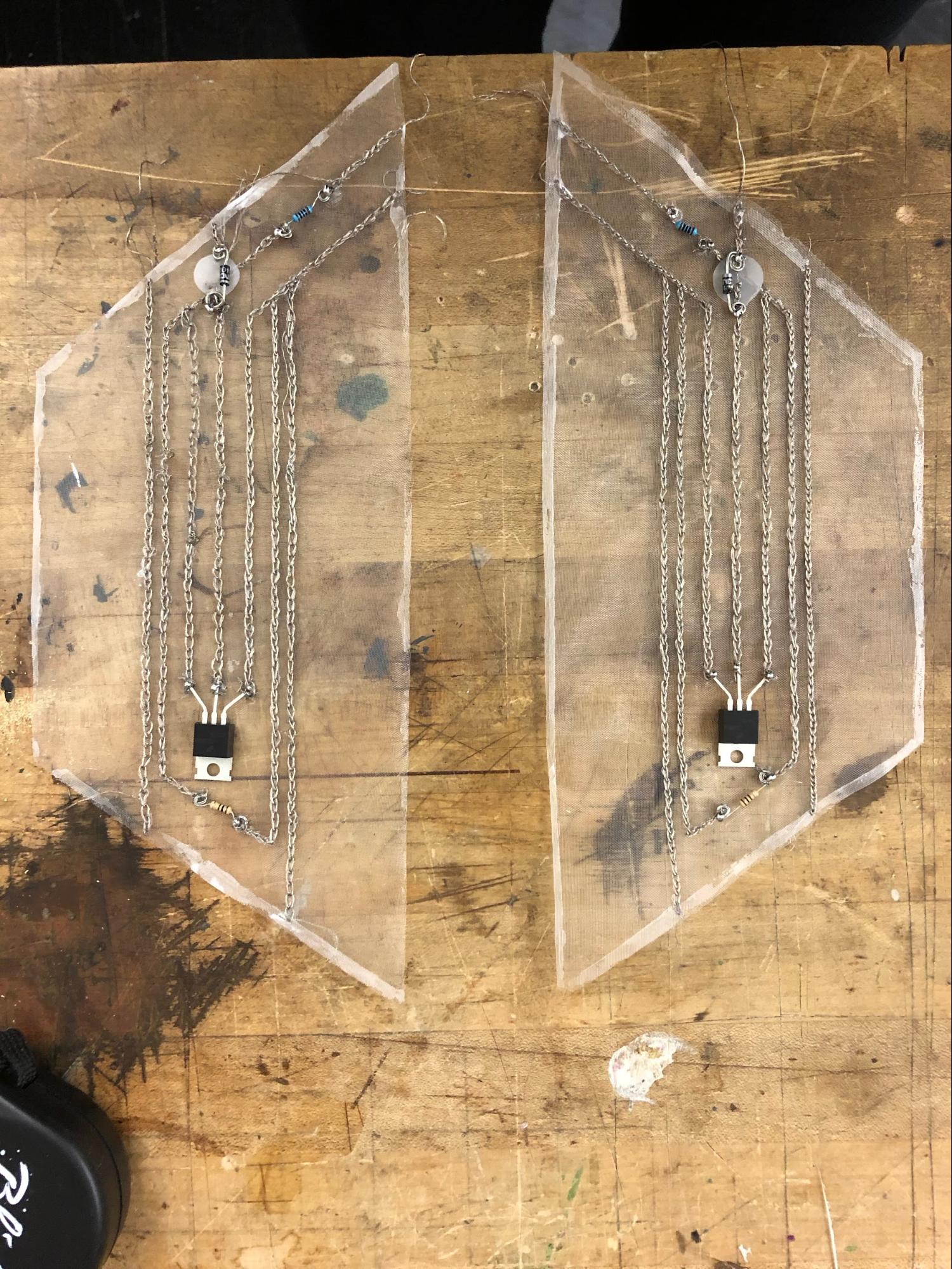
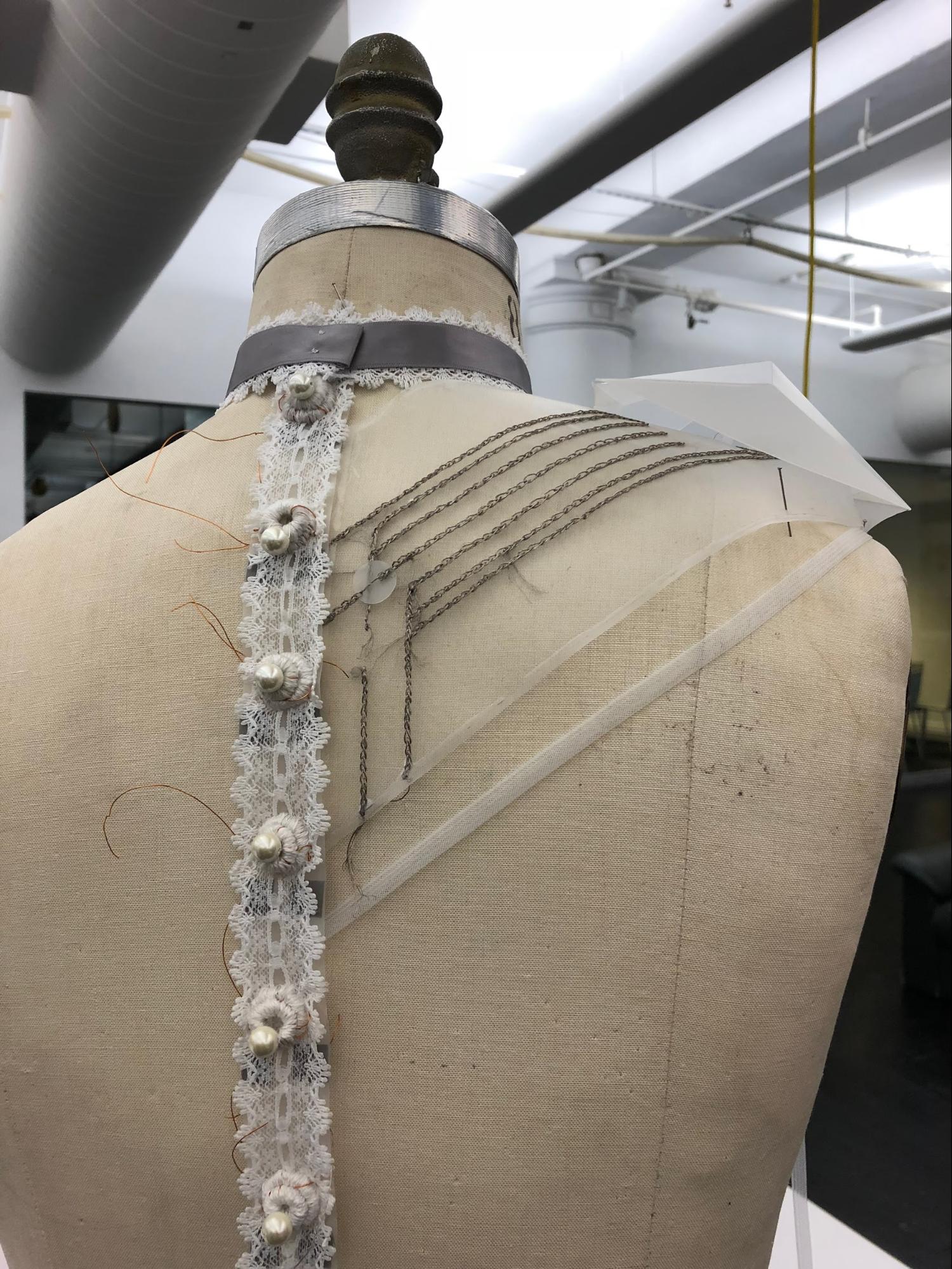
We attached the coils onto the lace with a plastic band to secure the movement and make sure the lace won’t break in the process of testing. We soldered the coils and attached them onto conductive threads. All top coils attached to left side of the circuit and all bottom coils are attached to the right side of the circuit.
Capacitive sensor
We also made a capacitive sensor onto the front of the choker and connected it to the Arduino through the back.
Assembling
Technology
Final Prototype Sketch

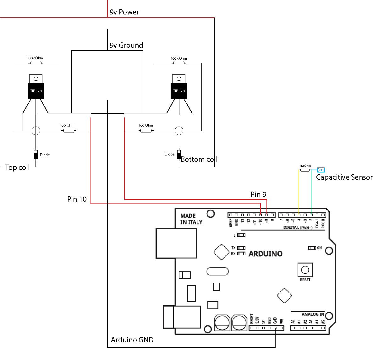
Circuit Sketch
Code
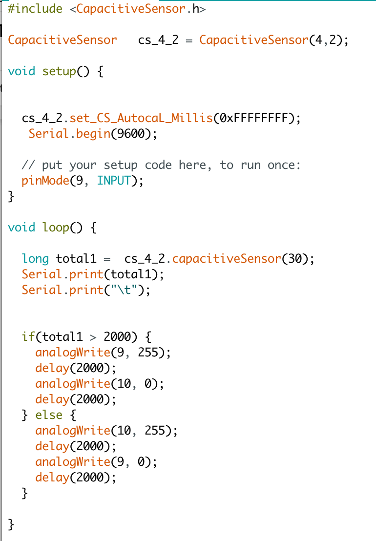
We used Arduino UNO and 2 9v batteries to power up the flip dots and capacitive sensor. There are 2 coils under each magnetic bead to facilitate the switching of power to activate the flip dots. The top coil would be controlled by one transistor and the bottom coil by another transistor. If the capacitive sensor is activated, then the top coil would activate and make the flip dots move downwards. Otherwise, it would remain upwards.
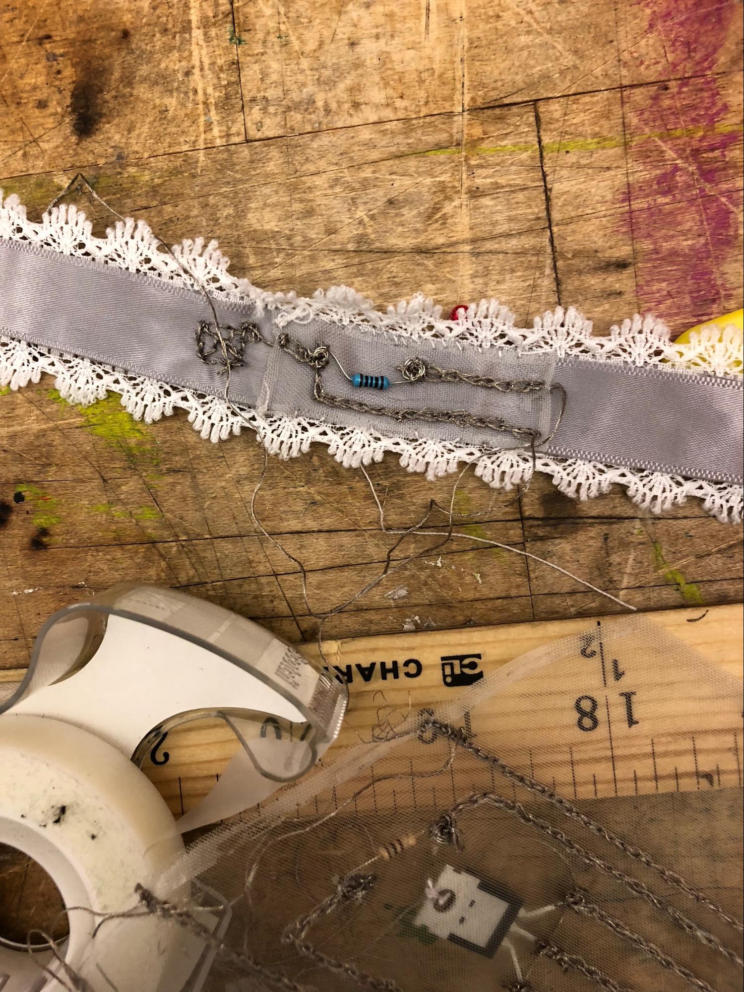
We had a lot of issues finding out how to power the 9 flip dots, as we were able to only move 5 with 18 volts of power. Once we tried applying more power, the conductive thread start sparkling at certain parts. One assumption we had is that there is too much resistance towards the tail of the back piece, making it hard for electricity to pass through. Another issue could have been that the sewing of the magnetic beads was wrong, so it is unable to move.
Final Outcome
Future Steps
We want to continue working on this project in order to make it a fully functional prototype. Moreover, the overall design of the exoskeleton made it difficult to test while assembling, so we need to rethink of a new way to allow the testing to be done while soldering the backpiece.