Author Archives: segoj297

Jed Segovia – Final Project: “Safe Crossing”


My Instructable.

My slides from the Final presentation.

Wins
– Making a critical game about human tragedy and suffering
– Making a flip dot game, flip dots are fun
– Making fun little game pieces with polymorph, which is now my favorite
– Seeing how creative and resourceful I get (I found a wooden sheet on D12 and just broke that apart to make the housing)

Challenges
– Soldering, aaaargh
– Tedium
– Making so many coils, using so much wire, wrapping so much yarn, in, out, in, out, soldering ends off, on, off, on, off, only to have it not work. Repeat, again, over, and over.

Learned
– Interactivity can be as simple as a magnet, coils, and a 9-volt battery

Where to go next
– Will present this to John Sharp and Colleen Macklin to get their feedback on how to improve the game narrative, mechanics, and aesthetics. I want this to be one of my jumping-off points towards being a critical game designer and experience artist.

Thank you for a great semester, Liza, Max, everyone! I learned a lot from this class and all of you. 🙂 Happy Holidays.


Jed Segovia – Zipper Switch Test 2 – Zipper Switches are Hard

2016-10-11-20-20-20

This is my entry documenting my second attempt at making a zipper switch. This time, I used a zipper with plastic teeth. I also brought beeswax (actually hair wax for dreadlocks) so that it can smoothen and tighten finicky conductive thread frayed ends.

2016-10-11-20-44-14

Threading conductive thread was still tricky, but I managed to sew the negative end of the battery through the underside of the zipper. And because it’s negative, I sewed the resistor and LED negative end into it. But if you’ll look closely, you’ll see I made the mistake of sowing through the positive end as well.

It’s tricky. When sowing, I got caught up with the idea of threading through the hole, not realizing that it would ruin the proper path of the circuit.

2016-10-11-20-49-40

So I snipped the thread connecting the negative and positive ends of the LEDs. I would sow it with thread but not close it.

2016-10-11-20-49-46 2016-10-11-20-55-45

You can see here I tested the connectivity of the battery holder to see if the LED was working.

2016-10-11-20-56-30

And here, you can see me testing the connectivity of the conductive thread patch through the negative diode. It works! The conductive thread is holding strong while the positive end of the battery is powering the LED through lobster clips.

2016-10-11-21-18-38

Here in this photo I’ve sown the negative end of the LED into the circuit and left it open. When I attach clips between the positive end of the battery holder into the positive leg of the LED, it lights up. Great!

2016-10-11-21-27-31

And here you’re seeing me test the connectivity of the positive leg that has been sown into the zipper with conductive thread. This time I left it open. And it works.

Just one problem…

2016-10-11-21-28-35

I sowed the thread with such a large gap between the teeth and thread that it doesn’t close up. Unlike Liza’s zipper switch, which is very carefully sowed to be as close to the teeth as possible, bridging it almost.

Zipping teeth this small is excruciatingly hard. Making a zipper switch is harder than it looks. It’s also painful in the fingers because I’m compelled to twist this and the zipper around to get the needle through.

2016-10-11-22-01-18 2016-10-11-22-05-11

So here, I tried closing the circuit by attaching the positive conductive thread patch to the negative thread patch. The connection on the negative side was too lose. The thread wasn’t wound tight enough. Max, our teaching assistant, recommended I solder the lose end.

2016-10-11-22-08-26 2016-10-11-22-09-39 2016-10-11-22-09-50 2016-10-11-22-09-55 2016-10-11-22-12-09

And there. With the loose ends soldered in…

2016-10-11-22-13-52

… the LED lights up when the circuit is closed.

Now that I’ve learned these, it’s off to buy another pair of plastic zippers. Little victories.

Jed Segovia – Zipper Switch Test for Midterm

For my midterm I plan to make a body bag.

What’s going to be inside? I don’t know yet. But our instructor Liza said that whatever should be inside, it has the potential to be powerful.

This is part of my thesis on violence. My original idea was that it would be a button that needs to be pressed to turn on a light. When I told Liza it would have a zipper, she told me to focus on either the zipper or the press.

“People I feel would be more likely to open a body bag zipper than actually touch it,” she said.

So! I decided I would make a zipper switch. This is a post documenting my first unsuccessful attempt to make a zipper switch.

UPDATE: THE TEETH WERE CONDUCTIVE AND THEREFORE DISRUPTING THE CIRCUIT. IT NEVER WOULD HAVE WORKED AS LONG AS THE TEETH WERE METAL AND CONDUCTIVE.

I spoke with classmate Audrey Fox who is a guru. She asked if maybe the teeth were conductive and recommended I take out a multimeter.

2016-10-10-22-09-27  2016-10-10-22-09-43

Connectivity. The teeth were conductive. Whereas…

2016-10-10-22-10-13

The zipper teeth in the swatch are not, because they’re plastic.

Wow. The answer was there in front of me the whole time. The circuit never would have worked. It needed plastic teeth to work.

I bought two zippers from Michaels. In a panic I took out the black one, and to my relief, THE TEETH WERE PLASTIC.

I’ll prototype the circuit with the black plastic teeth.

Thank you, Audrey.

Original post below.

2016-10-09-19-46-22 2016-10-09-19-47-25

This is Liza’s zipper switch swatch. I borrowed it to study how to construct it. I want a creepy red glow to come out of it when opened.

2016-10-09-19-40-20  2016-10-09-19-40-51

First, I bought a pair of zippers for prototyping. Since I had green fabric, I bought a green zipper. I needed to wind conductive thread between the zipper teeth to create enough conductivity to close a circuit.

2016-10-09-20-29-45


2016-10-10-14-07-28 2016-10-10-14-17-58

Threading conductive thread through a needle is annoying. The edges fray so easily. I read that I needed beeswax to clump it at the end. I didn’t have beeswax. I had hair glue. Which worked.

2016-10-10-14-37-13 2016-10-10-14-25-56

The thread kept getting frayed and stuck between the zipper teeth.

2016-10-10-14-44-55

Then comparing the zipper teeth from Liza’s swatch to my zipper, I saw that the teeth in my zipper were larger. Which made it difficult. Look how messy my attempt to sew is.


2016-10-10-14-34-32 2016-10-10-14-35-18

You can see how clumped it got.

2016-10-10-15-01-39 2016-10-10-15-13-19

Then I would sew the battery holder in with the LED and resistor.

2016-10-10-18-59-492016-10-10-19-15-51

It didn’t work.

2016-10-10-20-03-15

I tried a second attempt and that still didn’t work.

2016-10-10-20-03-19

Ugh. I’ll try again tomorrow.

Jed Segovia, Week 5: Ice Cream Sandwich Sensor Homework

My code for this project.

I wanted to make an easy sensor so I could focus my energy on the Arduino code.

I used the ice cream sandwich swatch example shared by Cat Schmitz. I cut a circle of foam, cut a hole in the middle, and sandwiched it between two velostat sheets. Now I needed lobster clips to complete the circuit.

When I got that working I tried using the sensor instead of a regular button in the typical Arduino Button sketch. I replaced the button with two lead wires, and lobster clipped them with my button. It didn’t work. I was dismayed because it looked like my sensor button wouldn’t work. I also realized the Arduino cable was broken, and not detecting my port. Another setback. I left to buy two Arduino USB cables at Tinkersphere in 5th Street, and I spent an hour doing that.

It wasn’t until I reviewed the previous week’s slides did I realize that there was a sketch called “ReadingSensorValues.” I couldn’t find it in the Arduino examples, and was at a loss, until my classmate Audrey pointed out there was a link to our instructor’s Github right under the slideshow. Thankfully Audrey pointed it out. I ran the sensor homework and voila, I got the sensor to produce a range of brightness in my LED.

Using this template, I would now scale it up to three LEDs. First, I scaled it to two.

Scaling it up to two, I wanted to activate the first LED immediately, and activate the second LED only after pressing down the button for a certain time.

I struggled to use an If/Then code, so I went with While, which is certainly interesting. My first successful attempt was turning on the white LED right away, and when the sensor is pressed, the blue LED lights up. When the blue LED’s value goes beyond 150, the white LED turns off.

I finally got three LEDs to work with if-then statements. The circuit is based on how much pressure is delivered on my button. The blue LED lights up first. When the blue LED value goes beyond 110, the white LED lights up. As long as I am pressing hard on the sensor, the values of both the blue and white LEDs go up. When the white LED value goes beyond 140, the yellow LED lights up.

Lovely. Seeing the LEDs light up with a range of brightness is exciting. Plenty of potential applications to many projects.

Now to see if I can synthesize this into my Internet of Things homework.

Jed Segovia: Swatches

2016-09-17-14-05-34 2016-09-17-14-05-42 2016-09-17-14-44-30 2016-09-17-15-09-20 2016-09-17-15-30-09 2016-09-17-15-30-21  2016-09-17-17-03-40 2016-09-17-17-08-23 2016-09-17-17-20-02 2016-09-17-17-53-55 2016-09-17-18-05-50 2016-09-17-18-11-11 2016-09-17-18-20-01 2016-09-18-15-25-21 2016-09-18-19-42-54

I personally had fun with this because I learned how to sew!

I decided to make a simple button based on the example our instructor showed us in class. She used foam, velostat, alligator wires, an LED, and a 9V battery.

I thought about doing something similar with the conductive thread. But since I was a first-time sewer, I didn’t have time to figure out how to work the conductive thread. Instead, I went for a simple 3V coin battery and LED circuit combination.

I made a circuit sandwich with two pieces of foam and stitched fabric. I put the button inside and essentially sewed up a light-up pillow.

Jed Segovia – Illustration Project – The Little Red Hen

2016-09-12-21-12-23

My chosen passage is from The Tale of the Little Red Hen.

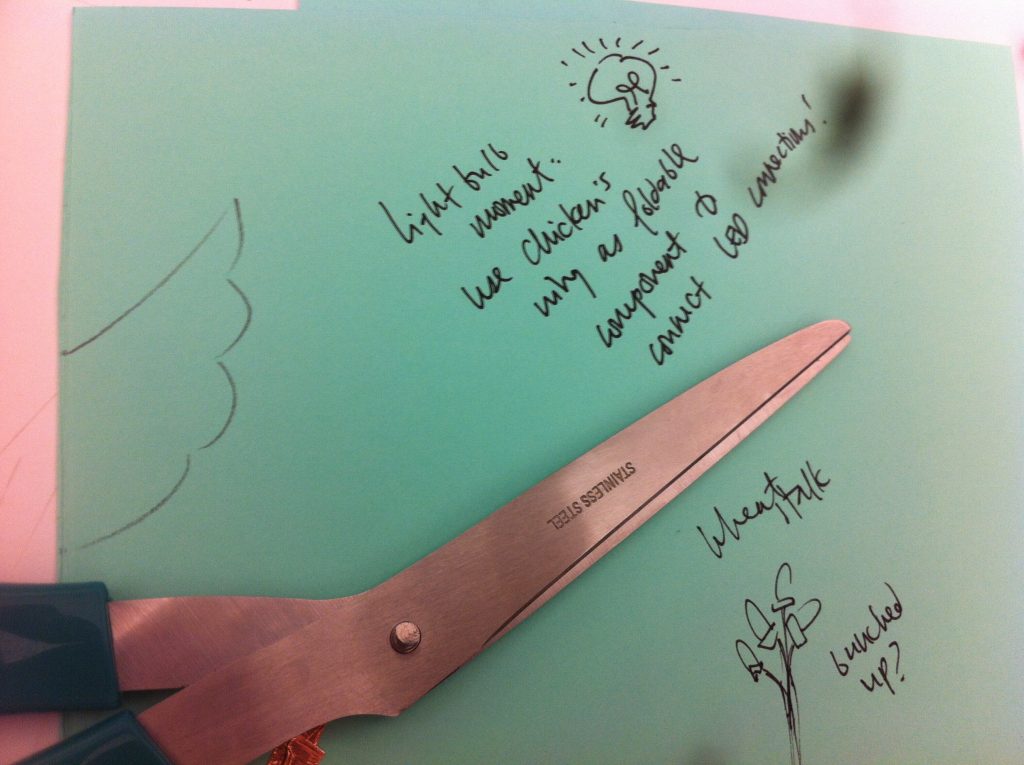
Here is my sketch of how I wanted it to look.

2016-09-12-19-10-39

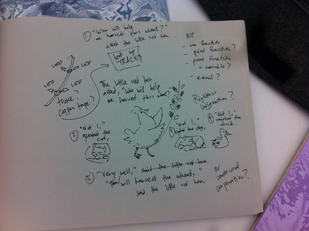
I wanted the wheat to be the central piece of the illustration. I wanted to use yellow LEDs as the wheat buds. So the hard part was crafting traces to give it a smooth, organic look for the wheat stalk. Once I had the circuit done, I would illustrate around it.

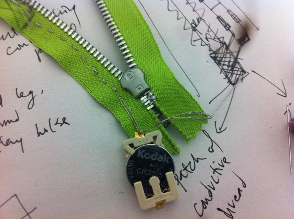
I decided to make a parallel circuit because I learned last class that series circuits don’t work with 3V batteries.

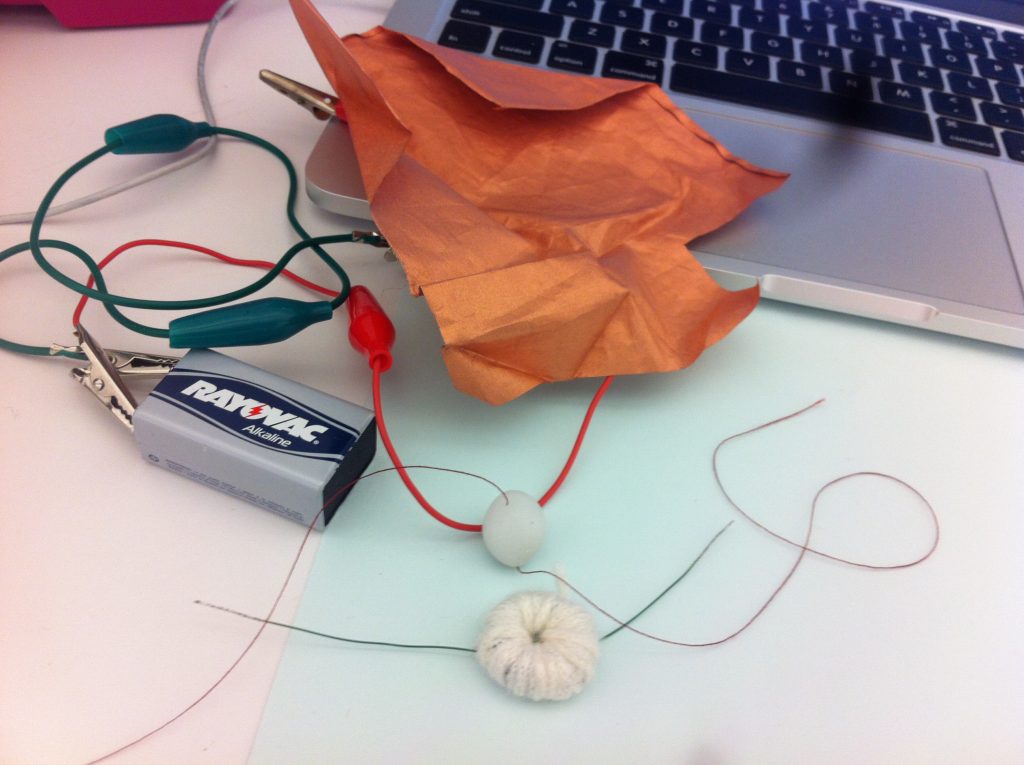
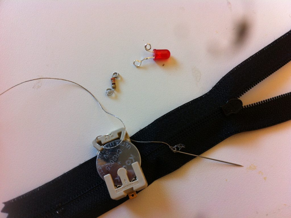
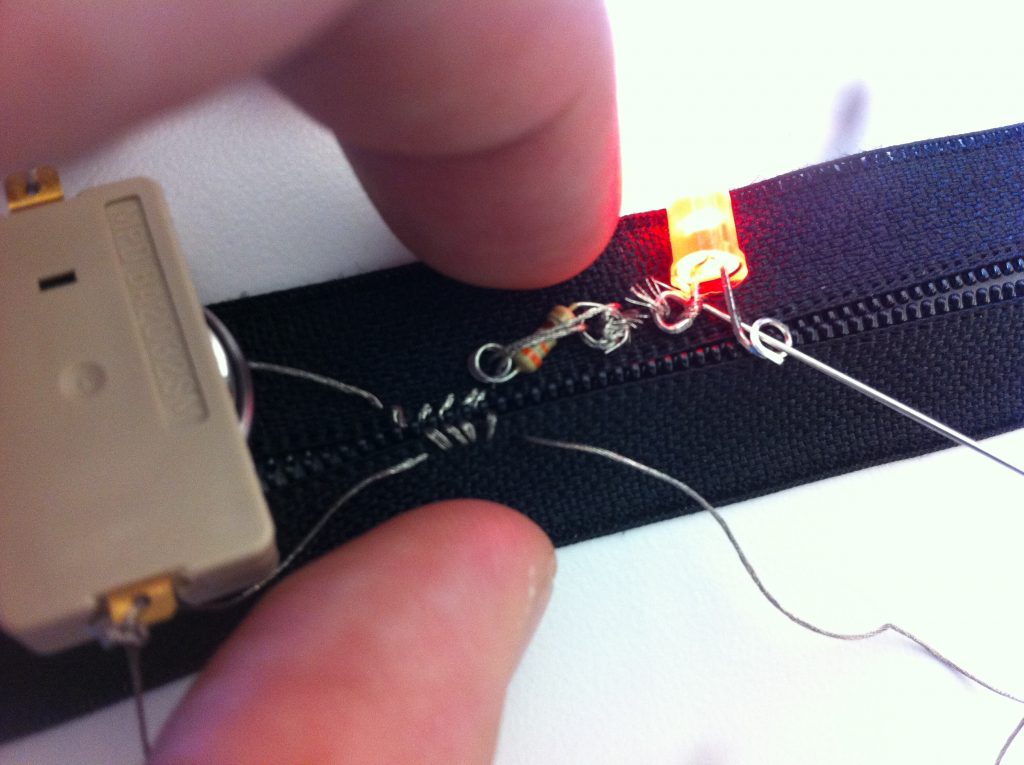
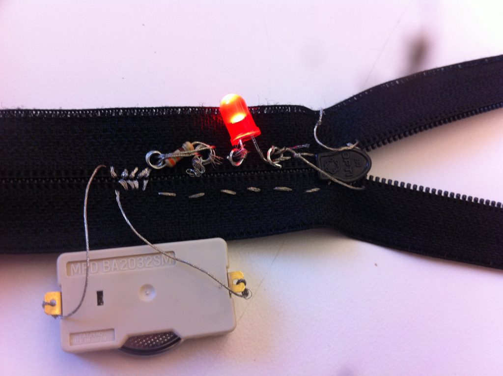
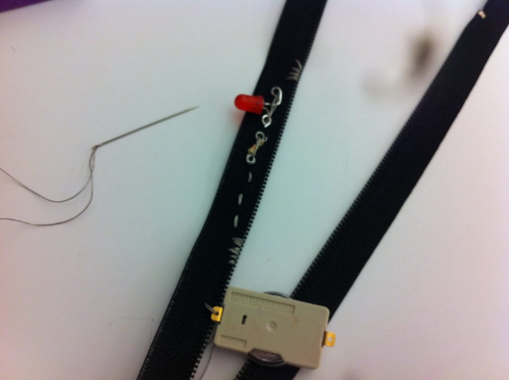
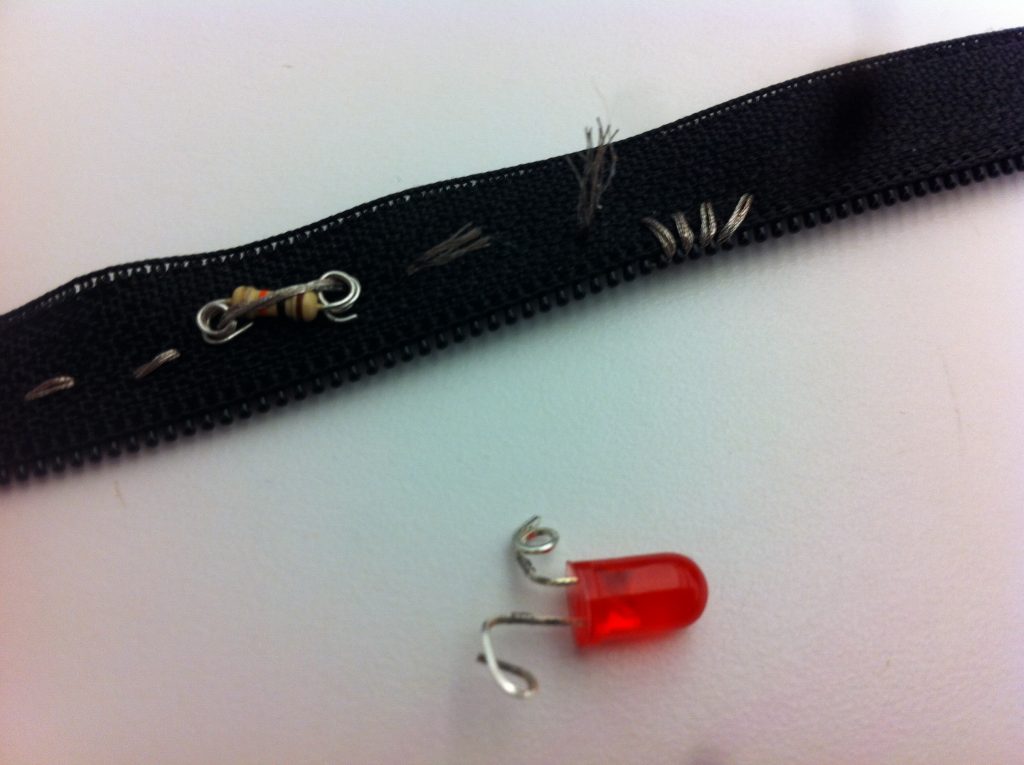
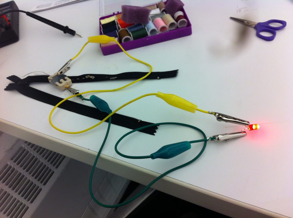
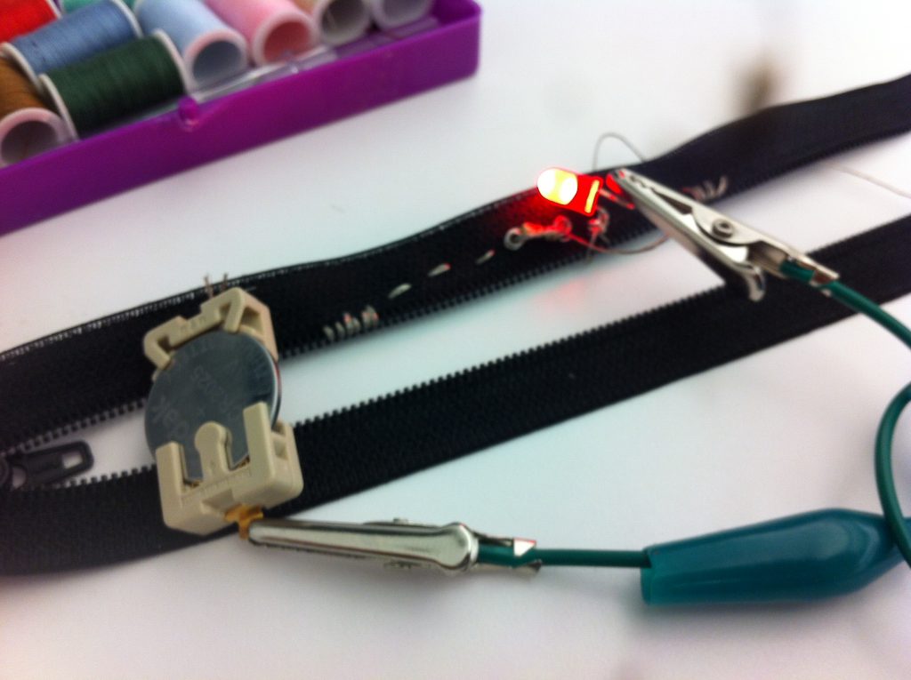
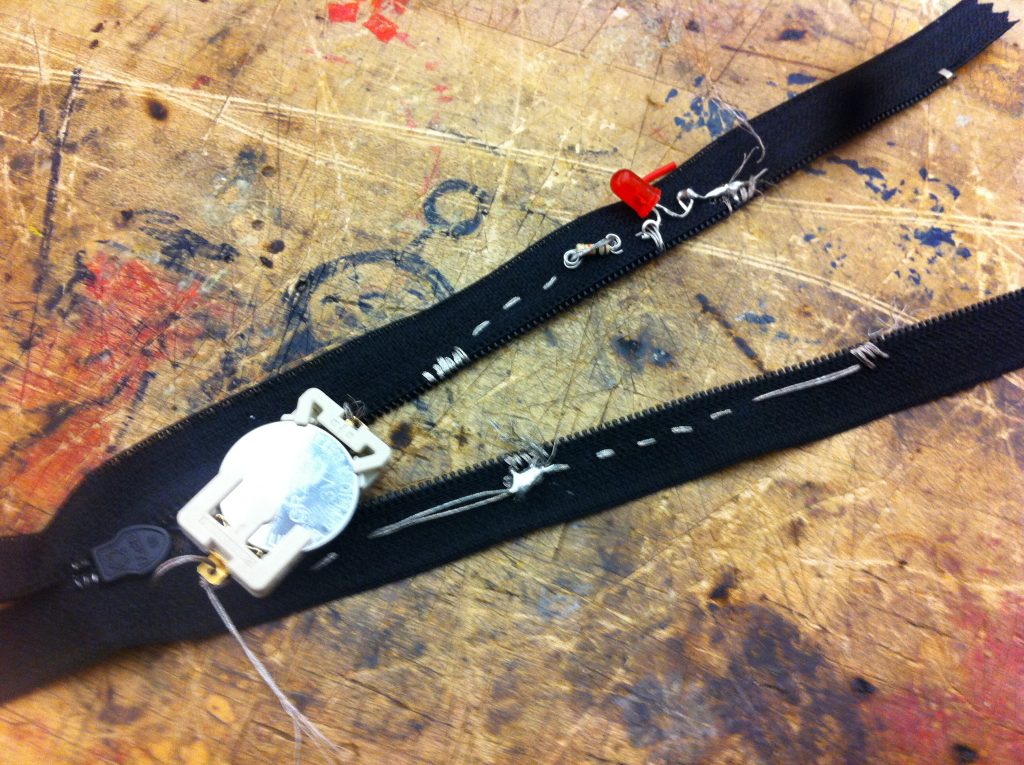
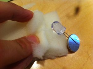
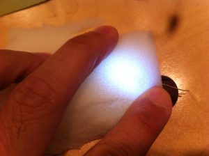
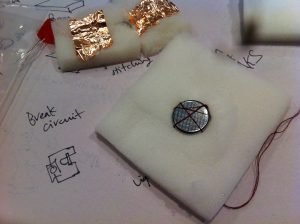
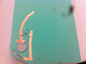
I first did testing of the Simple Circuit Diagram, using High-Low Tech’s tutorial as a reference. 

2016-09-12-14-43-58 2016-09-12-14-44-01

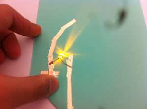
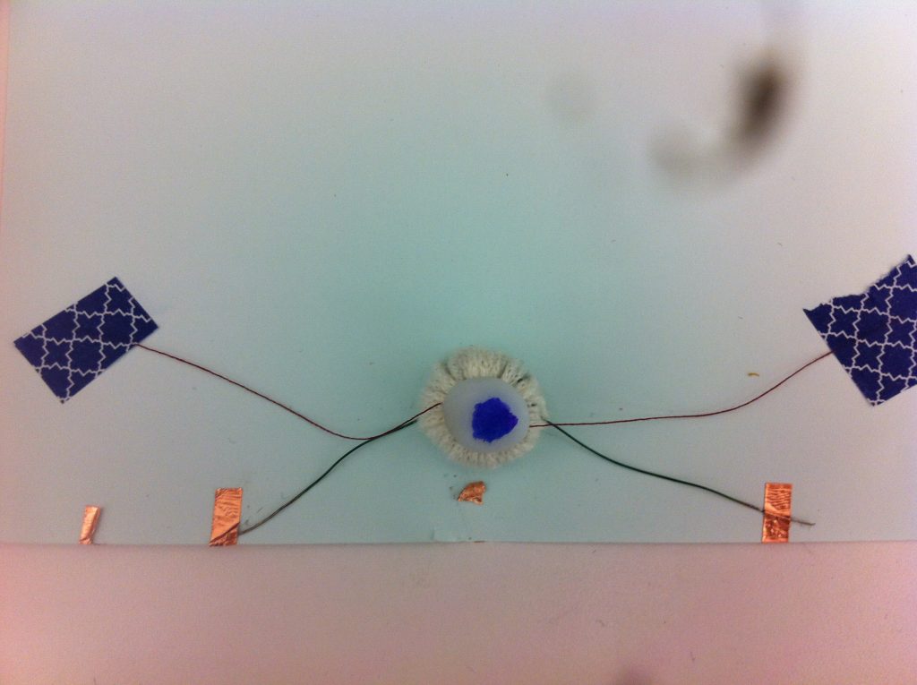
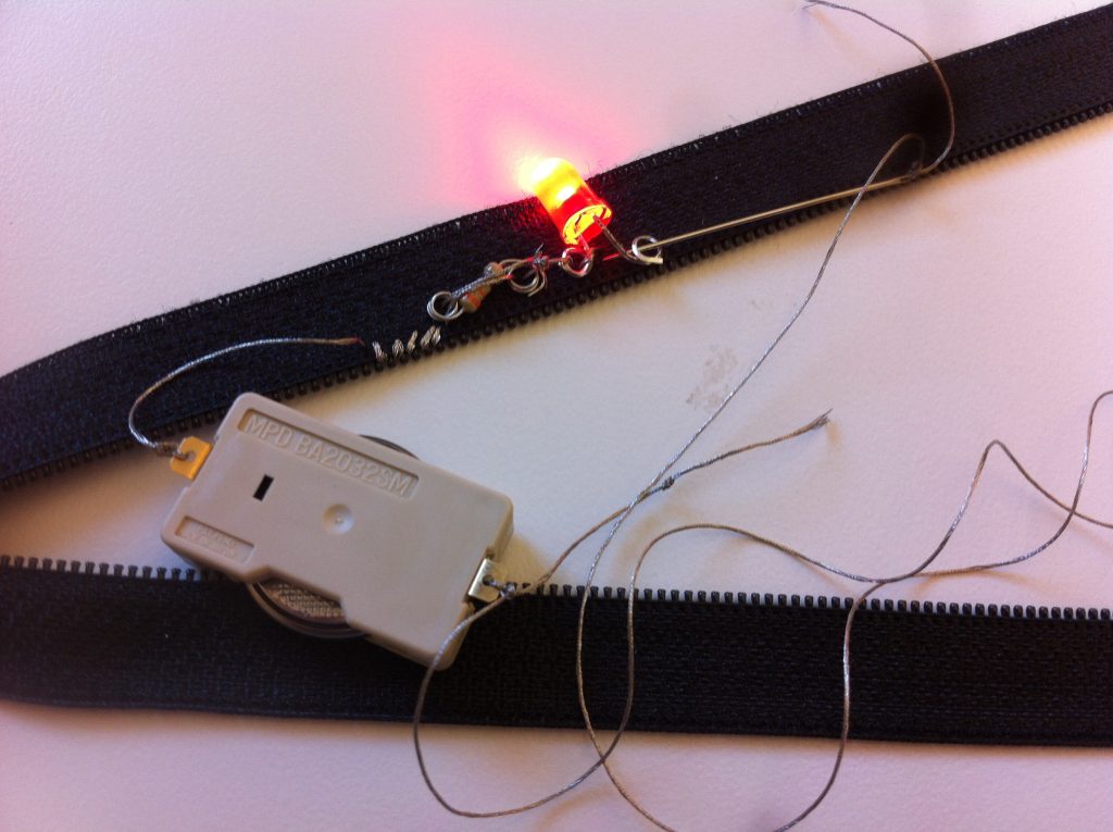
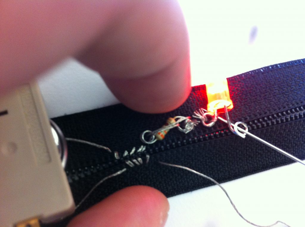
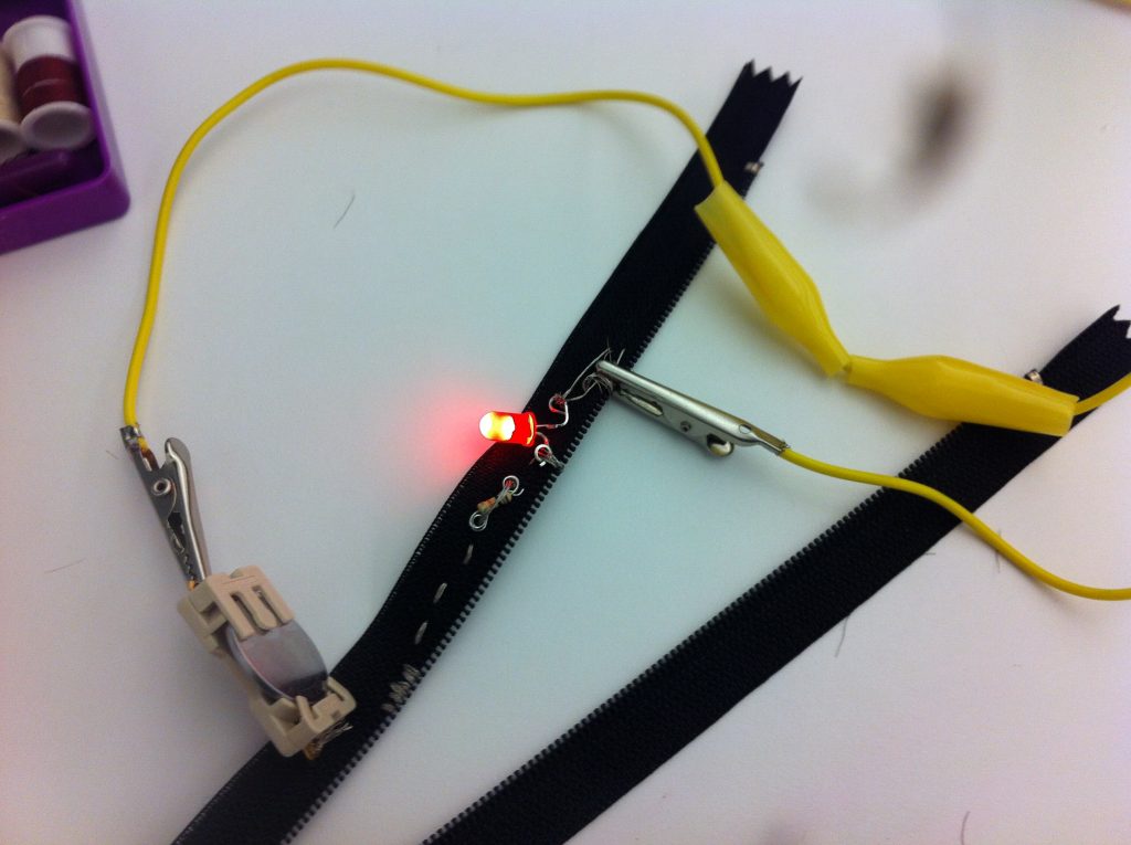
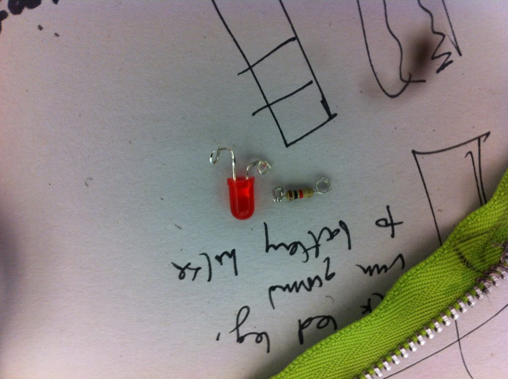
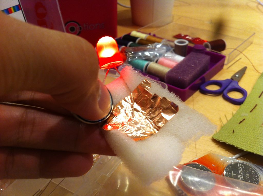
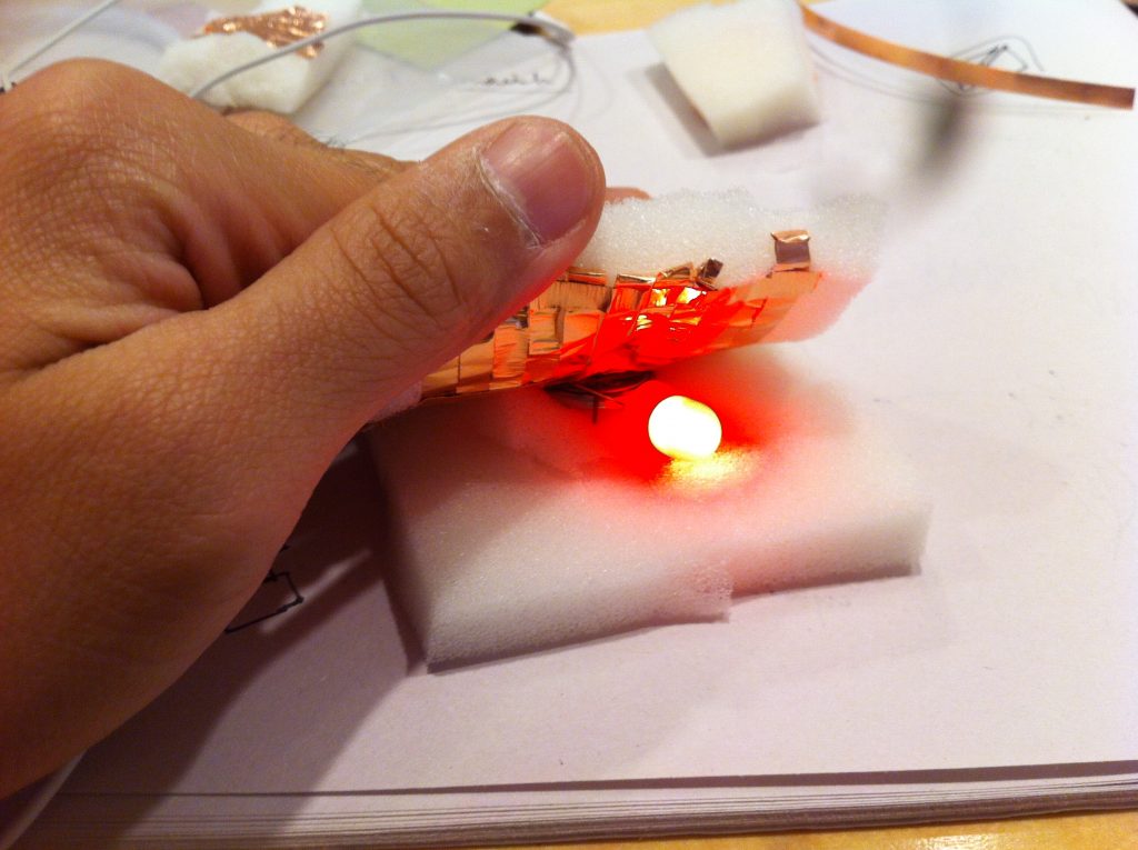
Once I got one LED lit up, I added a second LED. This time, I added a second trace.

2016-09-12-14-52-05 2016-09-12-14-52-13

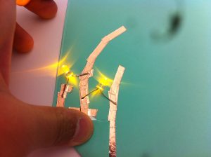
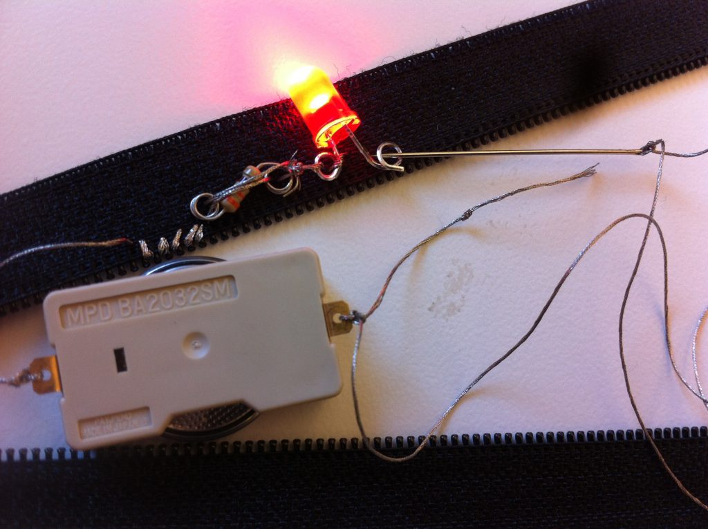
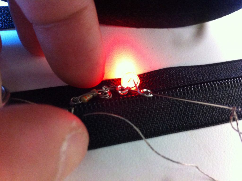
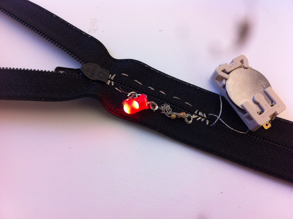
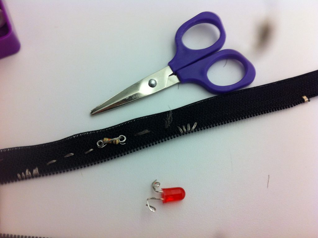
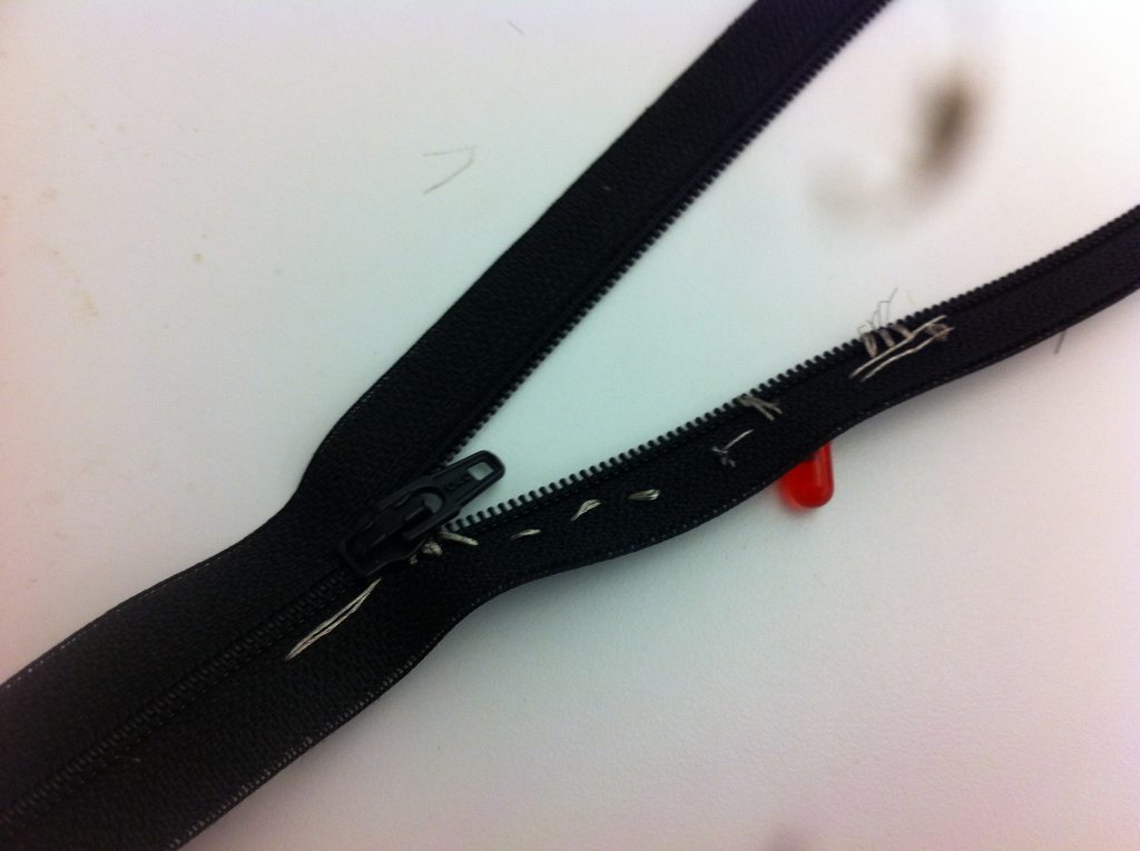
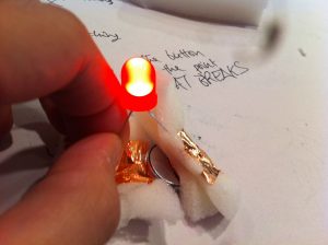
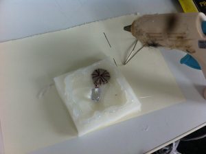
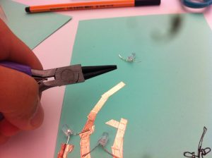
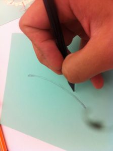
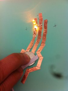
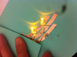
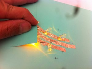
Once I got those in, I felt confident. Now I wanted to add a third LED. This time, I wanted to bend the LED nodes so it wouldn’t be awkwardly sticking out. I took out my long-nose pliers and tested it out, by bending the nodes.

2016-09-12-14-57-18 2016-09-12-14-57-46

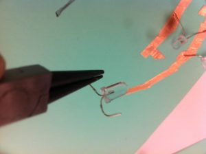
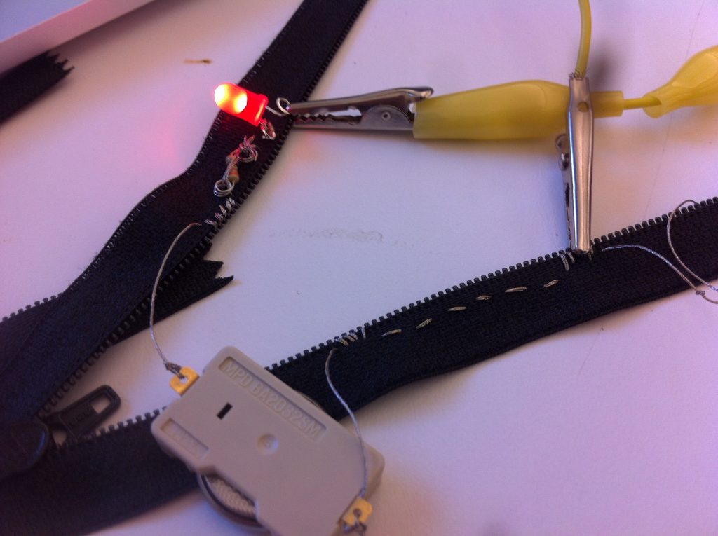
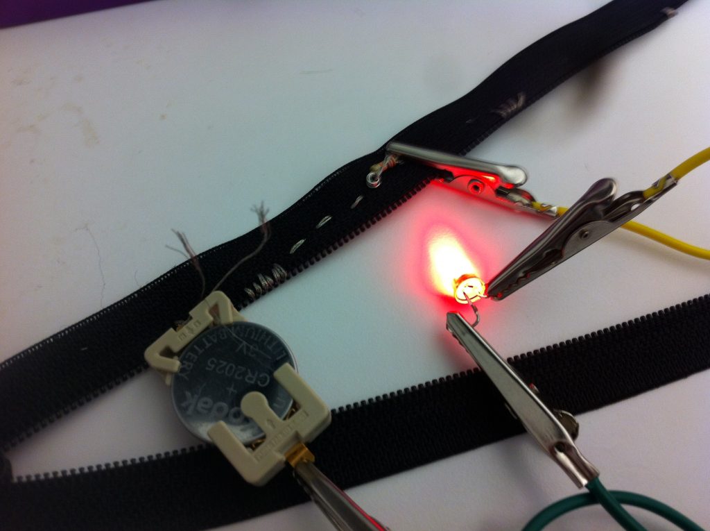
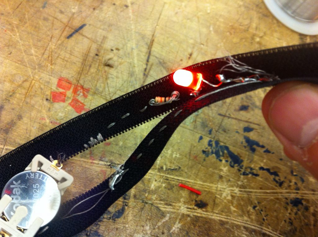
So you can see, I got it curved nicely. And once I got that working…
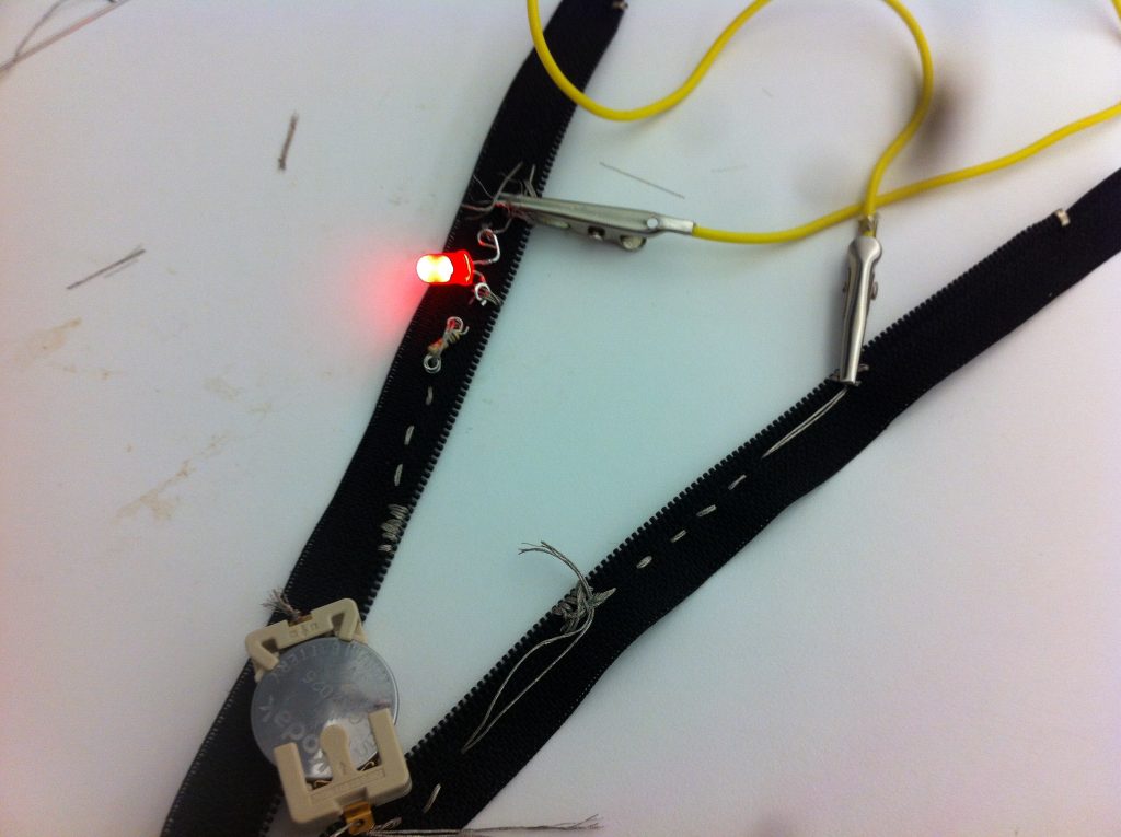
2016-09-12-15-00-33

Three LEDs!

So I sketched out a diagram to refine the next iteration, once I got the principles working.

2016-09-12-15-00-36

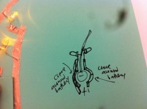
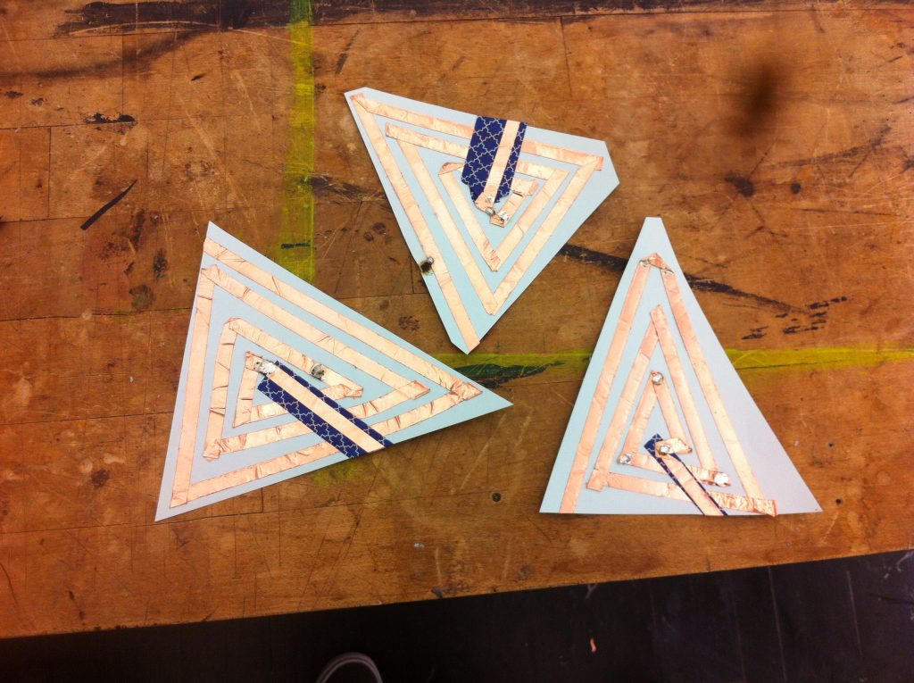
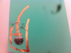
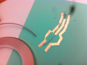
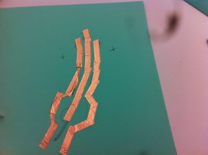
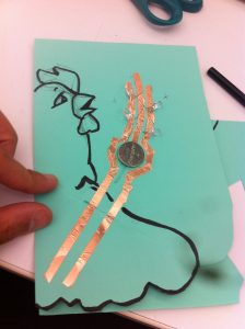
I couldn’t figure out how to hide the battery in the time I had. So I worked a diagram that at least aestheticized the circuit. So I went to sketching the illustration. First, I drew out the wheat stalk, that would serve as the circuit path. This would be the negative path. Then I followed by adding two positive paths. Once those were drawn in, I added copper tape.

2016-09-12-15-09-42 2016-09-12-15-26-43 2016-09-12-15-28-31

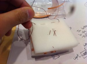
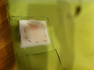
Then I hit a problem: how to activate the circuit? I first thought about making a pop-up component: I would put in a folding wing and integrate it into the illustration. The wing would be the chicken’s wing, with copper tape put into it. So I tested that.

2016-09-12-19-47-56 2016-09-12-19-54-13

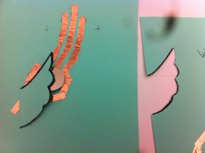
As you can see, I ran into problems right away. I didn’t measure the wing so it wasn’t large enough to cover both the circuit and allow for space to be taped into the paper.

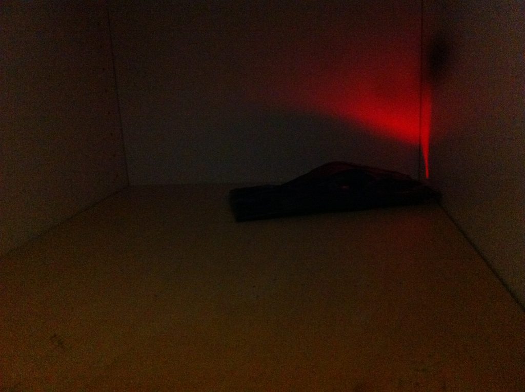
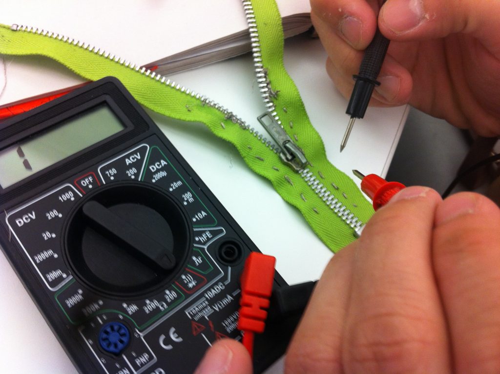
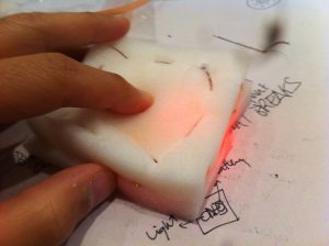
I hit an impasse of forty minutes. Forty minutes of frustration and panic because I couldn’t get the circuit to work. Was it because the copper tape wasn’t connected enough? Were the LEDs loose? I had no idea. I got it to light up but not totally.

2016-09-12-20-04-34

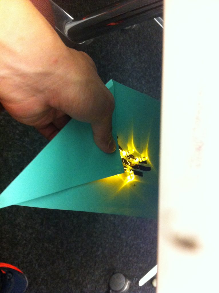
Then I kept looking at my first circuit, which was working…

2016-09-12-15-00-33

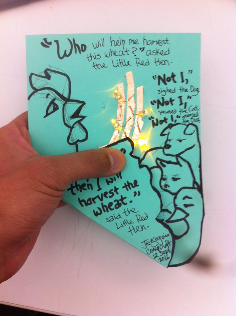
So why not use that, and stylize the folding corner as a wing? That was born out of necessity than anything, but it was a great creative solution to me.
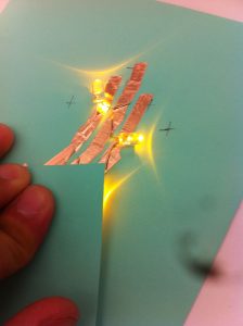
2016-09-12-20-35-45

So there!

2016-09-12-20-45-362016-09-12-20-43-18  2016-09-12-20-45-28

Now it was a matter of illustrating the scene, and integrating the circuit solution into it.

2016-09-12-20-58-052016-09-12-20-58-09 2016-09-12-21-12-072016-09-12-21-12-36   2016-09-12-21-12-23

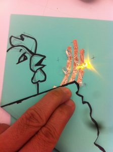
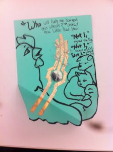
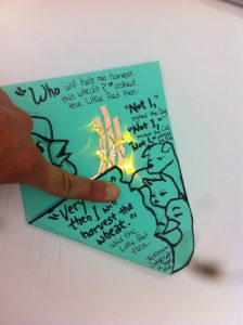
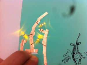
And there we have it! A scene from the Tale of the Little Red Hen, with light-up LED wheat buds. I’m really, really happy it works. It needs a lot of hard pressing to light up, but it lights up, and to me, looks GREAT.


[EDIT: Wait… I reviewed the homework and it said it wasn’t supposed to be “interactive.” Is… this interactive?]